Page 133 of 1575
(7)Disconnect the bank 2 CMP sensor connector(A) and the ECT(Engine Coolant Temperature) sensor
connector(B).
(8)Disconnect the bank 2 front/rear O2 sensor connectors(A,B) and the CKP sensor connector(C).
(9)Disconnect the bank 1 CMP sensor connector(A).
4.Remove the PCV(Pulge Control Valve) hose(A).
Page 205 of 1575
2007 > 2.7L V6 GASOLINE >
INSPECTION
1.Disconnect the vacuum hose from the throttle body, and connect a vacuum pump to the vacuum hose.
2. Check the following points when the engine is cold [engine coolant temperature 60°C(140°F) or below] and when it
is warm [engine coolant temperature 80°C(176°F) or higher].
WHEN ENGINE IS COLD
Engine operating condition Applied vacuumResult
Idling 50 kPa
(7.3 psi) Vacuum is held
3,000 rpm
WHEN ENGINE IS WARM Engine operating condition Applied vacuumResult
Idling 50 kPa
(7.3 psi) Vacuum is held
Within 3 minutes after engine start at 3,000
rpm Try to apply vacuum
Vacuum is released
After 3 minutes have passed after engine
start at 3,000 rpm 50 kPa
(7.3 psi) Vacuum will be held momentarily,
after which, it will be released
Page 230 of 1575

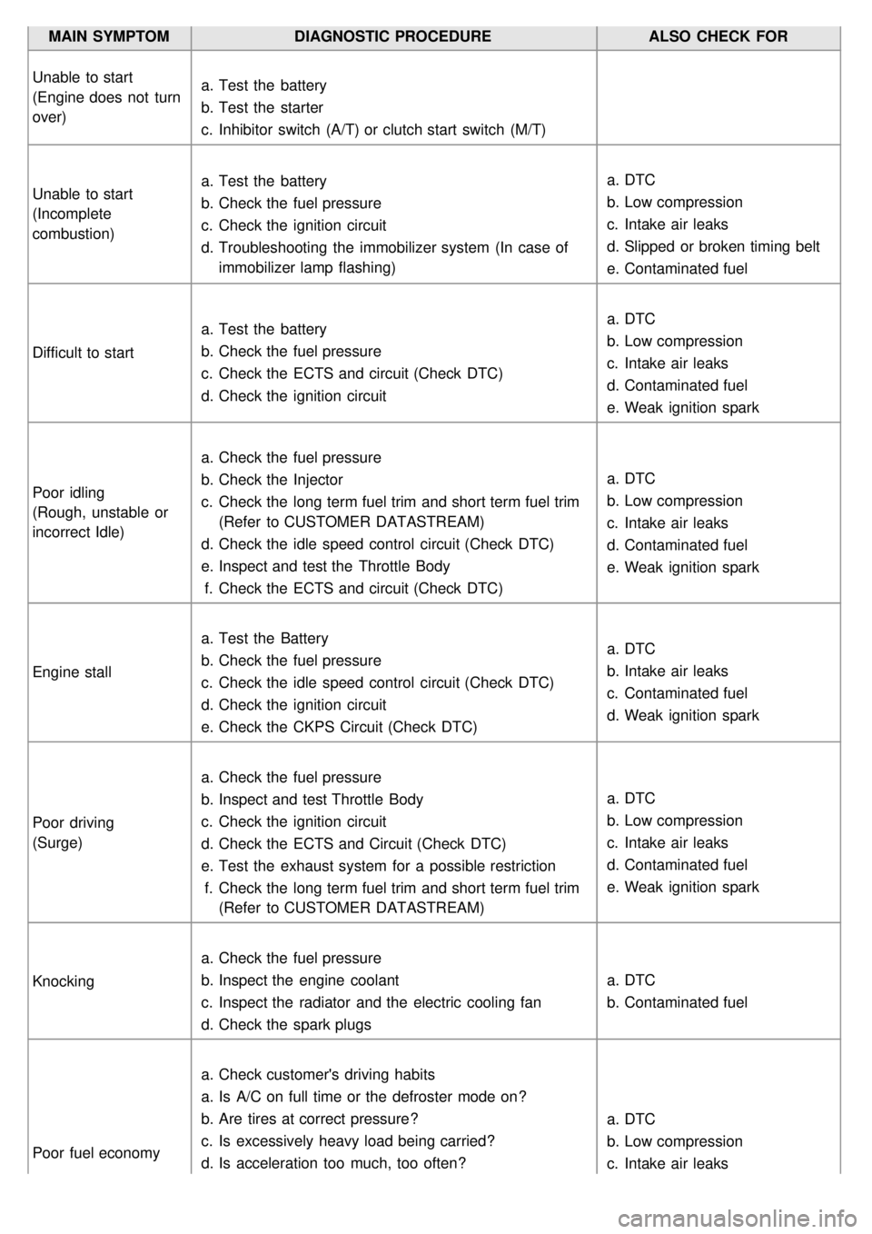
MAIN SYMPTOMDIAGNOSTIC PROCEDURE ALSO CHECK FOR
Unable to start
(Engine does not turn
over) a.
Test the battery
b. Test the starter
c. Inhibitor switch (A/T) or clutch start switch (M/T)
Unable to start
(Incomplete
combustion) a.
Test the battery
b. Check the fuel pressure
c. Check the ignition circuit
d. Troubleshooting the immobilizer system (In case of
immobilizer lamp flashing) a.
DTC
b. Low compression
c. Intake air leaks
d. Slipped or broken timing belt
e. Contaminated fuel
Difficult to start a.
Test the battery
b. Check the fuel pressure
c. Check the ECTS and circuit (Check DTC)
d. Check the ignition circuit a.
DTC
b. Low compression
c. Intake air leaks
d. Contaminated fuel
e. Weak ignition spark
Poor idling
(Rough, unstable or
incorrect Idle) a.
Check the fuel pressure
b. Check the Injector
c. Check the long term fuel trim and short term fuel trim
(Refer to CUSTOMER DATASTREAM)
d. Check the idle speed control circuit (Check DTC)
e. Inspect and test the Throttle Body
f. Check the ECTS and circuit (Check DTC) a.
DTC
b. Low compression
c. Intake air leaks
d. Contaminated fuel
e. Weak ignition spark
Engine stall a.
Test the Battery
b. Check the fuel pressure
c. Check the idle speed control circuit (Check DTC)
d. Check the ignition circuit
e. Check the CKPS Circuit (Check DTC) a.
DTC
b. Intake air leaks
c. Contaminated fuel
d. Weak ignition spark
Poor driving
(Surge) a.
Check the fuel pressure
b. Inspect and test Throttle Body
c. Check the ignition circuit
d. Check the ECTS and Circuit (Check DTC)
e. Test the exhaust system for a possible restriction
f. Check the long term fuel trim and short term fuel trim
(Refer to CUSTOMER DATASTREAM) a.
DTC
b. Low compression
c. Intake air leaks
d. Contaminated fuel
e. Weak ignition spark
Knocking a.
Check the fuel pressure
b. Inspect the engine coolant
c. Inspect the radiator and the electric cooling fan
d. Check the spark plugs a.
DTC
b. Contaminated fuel
Poor fuel economy a.
Check customer's driving habits
a. Is A/C on full time or the defroster mode on?
b. Are tires at correct pressure?
c. Is excessively heavy load being carried?
d. Is acceleration too much, too often? a.
DTC
b. Low compression
c. Intake air leaks
Page 233 of 1575
20683.51
40 1041.47
60 1400.67
80 1760.33
MANIFOLD ABSOLUTE PRESSURE SENSOR (MAPS)
�J Type: Piezo- resistive pressure type
�J Specification Pressure (kPa) Output Voltage (V)
20.0kPa 0.79
46.66kPa 1.84
101.32kPa 4.0
ENGINE COOLANT TEMPERATURE SENSOR (ECTS)
�J Type: Thermistor type
�J Specification Temperature Resistance (kΩ)
°C °F
- 40 - 4048.14
- 20 -414.13 ~ 16.83
0 325.79
20 682.31 ~ 2.59
40 104 1.15
60 140 0.59
80 176 0.32
THROTTLE POSITION SENSOR (TPS)
�J Type: Variable resistor type
�J Specification (When reference voltage = 5.0V) Throttle Angle (°) Output Voltage(V)
TPS1 TPS2
0 05.0
10 0.54.5
20 0.94.1
30 1.43.6
40 1.83.2
50 2.32.7
60 2.72.3
70 3.21.8
80 3.61.4
90 4.10.9
100 4.50.5
110 5.00.0
Page 236 of 1575
![KIA CARNIVAL 2007 Workshop Manual Coil Resistance (Ω)6.7 ~ 7.7 [20°C (68°F)]
CVVT OIL CONTROL VALVE (OCV) [BANK 2]
�J Specification Item Specification
Coil Resistance (Ω) 6.7 ~ 7.7 [20°C (68°F)]
ETC MOTOR
�J Specificati KIA CARNIVAL 2007 Workshop Manual Coil Resistance (Ω)6.7 ~ 7.7 [20°C (68°F)]
CVVT OIL CONTROL VALVE (OCV) [BANK 2]
�J Specification Item Specification
Coil Resistance (Ω) 6.7 ~ 7.7 [20°C (68°F)]
ETC MOTOR
�J Specificati](/manual-img/2/57045/w960_57045-235.png)
Coil Resistance (Ω)6.7 ~ 7.7 [20°C (68°F)]
CVVT OIL CONTROL VALVE (OCV) [BANK 2]
�J Specification Item Specification
Coil Resistance (Ω) 6.7 ~ 7.7 [20°C (68°F)]
ETC MOTOR
�J Specification Item Specification
Coil Resistance (Ω) 1.275 ~ 1.725 [20°C (68°F)]
IGNITION COIL
�J Type: Stick type
�J Specification Item Specification
1st Coil Resistance (Ω) 0.62Ω±10�Ë [20°C (68°F)]
2nd Coil Resistance (kΩ) 7.0kΩ±15�Ë [20°C (68°F)]
SERVICE STANDARD
Ignition Timing BTDC 7°± 10°
Idle Speed A/CON OFF
Neutral,N,P - range
650 ± 100 rpm
D- range 650 ± 100 rpm
A/CON ON Neutral,N,P - range
650 ± 100 rpm
D- range 650 ± 100 rpm
TIGHTENING TORQUES
ENGINE CONTROL SYSTEM
Item kgf·mN·mlbf·ft
PCM installation bolts (on bracket) 1.0 ~ 1.29.8 ~ 11.8 7.2 ~ 8.7
PCM bracket installation bolts/nuts (on air cleaner assembly) 1.0 ~ 1.29.8 ~ 11.8 7.2 ~ 8.7
Camshaft position sensor [Bank 1] installation bolt 0.7 ~ 1.06.9 ~ 9.85.1 ~ 7.2
Camshaft position sensor [Bank 2] installation bolt 0.7 ~ 1.06.9 ~ 9.85.1 ~ 7.2
Crankshaft position sensor installation bolt 0.7 ~ 1.06.9 ~ 9.85.1 ~ 7.2
CVVT Oil control valve [Bank 1] installation bolt 0.8 ~ 1.07.8 ~ 9.85.8 ~ 7.2
CVVT Oil control valve [Bank 2] installation bolt 0.8 ~ 1.07.8 ~ 9.85.8 ~ 7.2
CVVT Oil temperature sensor installation 2.0 ~ 4.019.6 ~ 39.2 14.5 ~ 28.9
Engine coolant temperature sensor installation 2.0 ~ 4.019.6 ~ 39.2 14.5 ~ 28.9
ETC module installation bolt 0.9 ~ 1.18.8 ~ 10.8 6.5 ~ 8.0
Heated oxygen sensor (Bank 1 / Sensor 1) installation 3.5 ~ 4.534.3 ~ 44.1 25.3 ~ 32.6
Heated oxygen sensor (Bank 1 / Sensor 2) installation 3.5 ~ 4.534.3 ~ 44.1 25.3 ~ 32.6
Heated oxygen sensor (Bank 2 / Sensor 1) installation 3.5 ~ 4.534.3 ~ 44.1 25.3 ~ 32.6
Page 239 of 1575

2007 > 2.7L V6 GASOLINE >
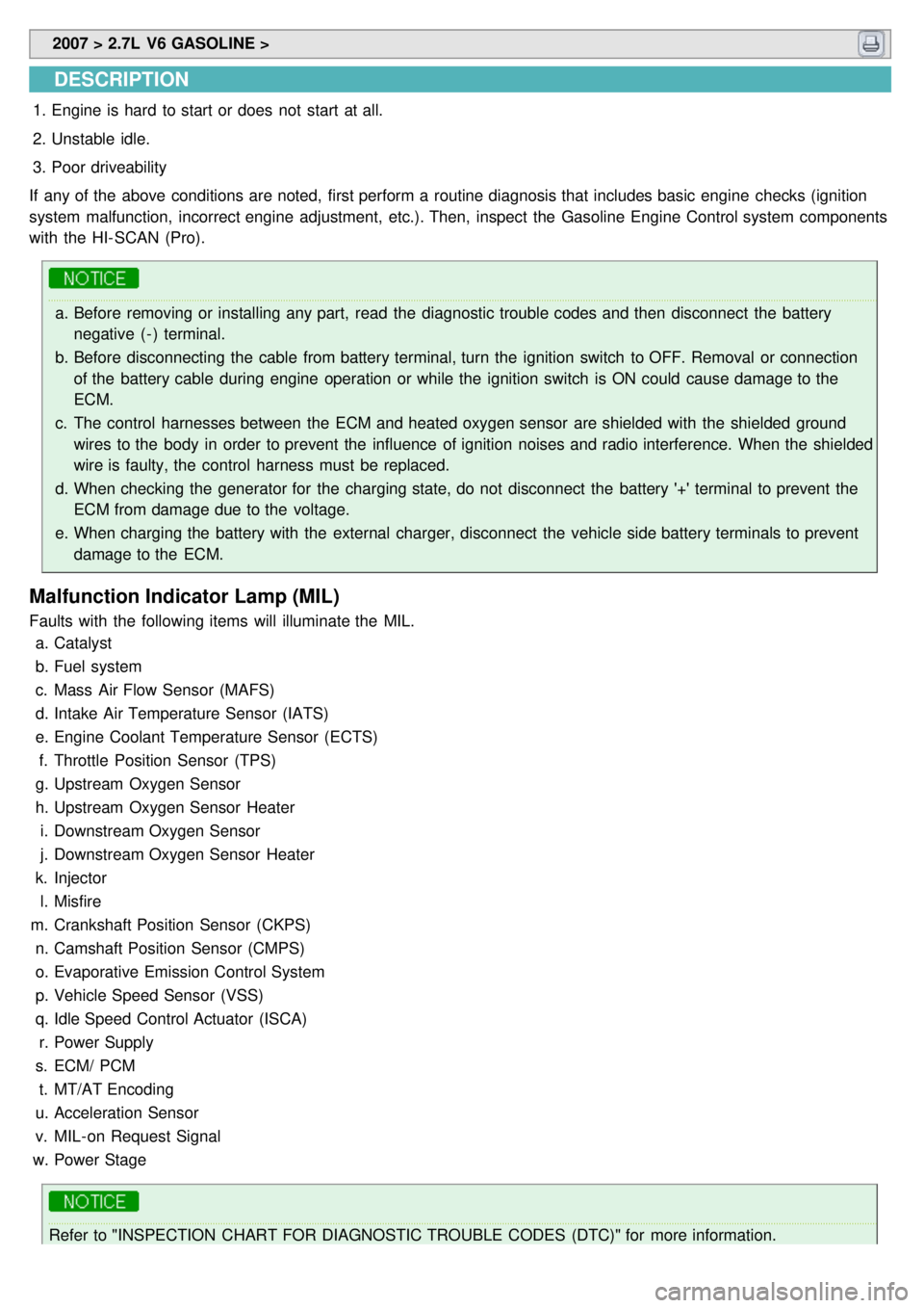
DESCRIPTION
1.Engine is hard to start or does not start at all.
2. Unstable idle.
3. Poor driveability
If any of the above conditions are noted, first perform a routine diagnosis that includes basic engine checks (ignition
system malfunction, incorrect engine adjustment, etc.). Then, inspect the Gasoline Engine Control system components
with the HI- SCAN (Pro).
a. Before removing or installing any part, read the diagnostic trouble codes and then disconnect the battery
negative ( - ) terminal.
b. Before disconnecting the cable from battery terminal, turn the ignition switch to OFF. Removal or connection
of the battery cable during engine operation or while the ignition switch is ON could cause damage to the
ECM.
c. The control harnesses between the ECM and heated oxygen sensor are shielded with the shielded ground
wires to the body in order to prevent the influence of ignition noises and radio interference. When the shielded
wire is faulty, the control harness must be replaced.
d. When checking the generator for the charging state, do not disconnect the battery '+' terminal to prevent the
ECM from damage due to the voltage.
e. When charging the battery with the external charger, disconnect the vehicle side battery terminals to prevent
damage to the ECM.
Malfunction Indicator Lamp (MIL)
Faults with the following items will illuminate the MIL.
a. Catalyst
b. Fuel system
c. Mass Air Flow Sensor (MAFS)
d. Intake Air Temperature Sensor (IATS)
e. Engine Coolant Temperature Sensor (ECTS)
f. Throttle Position Sensor (TPS)
g. Upstream Oxygen Sensor
h. Upstream Oxygen Sensor Heater
i. Downstream Oxygen Sensor
j. Downstream Oxygen Sensor Heater
k. Injector
l. Misfire
m. Crankshaft Position Sensor (CKPS)
n. Camshaft Position Sensor (CMPS)
o. Evaporative Emission Control System
p. Vehicle Speed Sensor (VSS)
q. Idle Speed Control Actuator (ISCA)
r. Power Supply
s. ECM/ PCM
t. MT/AT Encoding
u. Acceleration Sensor
v. MIL- on Request Signal
w. Power Stage
Refer to "INSPECTION CHART FOR DIAGNOSTIC TROUBLE CODES (DTC)" for more information.
Page 240 of 1575

Faults with the following items will illuminate the MILa. Heated oxygen sensor (HO2S)
b. Mass Air Flow sensor (MAFS)
c. Throttle position sensor (TPS)
d. Engine coolant temperature sensor (ECTS)
e. Idle speed control actuator (ISCA)
f. Injectors
g. ECM
Refer to "INSPECTION CHART FOR DIAGNOSTIC TROUBLE CODES (DTC)" for more information.
1. After turning ON the ignition key, ensure that the light illuminates for about 5 seconds and then goes out.
2. If the light does not illuminate, check for an open circuit in the harness, a blown fuse or a blown bulb.
Self-Diagnosis
If a sensor connector is disconnected with the ignition switch turned on, the diagnostic trouble code (DTC) is
recorded. In this case, disconnect the battery negative terminal ( - ) for 15 seconds or more, and the diagnosis
memory will be erased.
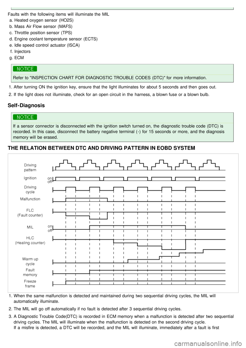
THE RELATION BETWEEN DTC AND DRIVING PATTERN IN EOBD SYSTEM
1.When the same malfunction is detected and maintained during two sequential driving cycles, the MIL will
automatically illuminate.
2. The MIL will go off automatically if no fault is detected after 3 sequential driving cycles.
3. A Diagnostic Trouble Code(DTC) is recorded in ECM memory when a malfunction is detected after two sequential
driving cycles. The MIL will illuminate when the malfunction is detected on the second driving cycle.
If a misfire is detected, a DTC will be recorded, and the MIL will illuminate, immediately after a fault is first
detected.
Page 241 of 1575
detected.
4. A Diagnostic Trouble Code(DTC) will automatically erase from ECM memory if the same malfunction is not detected
for 40 driving cycles.
a.A "warm- up cycle" means sufficient vehicle operation such that the coolant temperature has risen by at least
40 degrees Fahrenheit from engine starting and reaches a minimum temperature of 160 degress Fahrenheit.
b. A "driving cycle" consists of engine startup, vehicle operation beyond the beginning of closed loop operation.