Page 729 of 1575

3.The two coolant temperature sensors are installed to the heater inner. The sensor valves determine heater
operation.
4. One of the temperature sensors functions to prevent the heater from overheating.
If the sensor temperature valve exceeds 125°C, the fuel will be cut and the heater will be deactivated by the
determination of the overheating of the heater.
The other temperature sensor determines the operation mode of the fuel fired heater.The temperature of this
sensor enables to activate the heater at full load(5kw) or half load(2.5kw).
• The coolant temperature shown on the above Figure is the value of the inner sensor and the actual coolant
temperature is higher about 5°C ~7°C than the above value.
OPERATION
Switch on/ Operation start
The fuel fired heater is operated when the coolant temperature is below 68°C and the ambient temperature is below
2°C after starting the engine.
At this time, the glow plug and combustion air fan are operated first and after 30 seconds, the dosing pump is
operated with stopping the combustion fan for 3 seconds.
After that, the operation of the fan increases continuously until it approaches to full load within 56 seconds. If fuel
supply reaches to full load the glow plug does not operate and the operation of the fan reaches to full load.
After that the glow plug monitors ignition condition as a flame sensor for 45 seconds.
The above operation procedure is done automatically and in case the ignition fails, the above operation will be done
again automatically.
If the condition of ignition failure sustains continuously, fuel supply and fan operation will be stopped and error codes
will be stored to find cause of failure.
Generally, the cause of ignition failure during combustion is caused by the automatic re- operation of the above
procedure.
Operation for heating
The fuel fired heater operates at full load when the coolant temperature is below 68°C and the ambient temperature is
below 2°C after starting the engine.
It operates at half load when the coolant temperature is 74°C and it operates at idle mode when the coolant
temperature is 78°C.
The fuel fired heater during the transformation process does a cleaning function from the half mode to the idle mode.
At idle mode, all components do not work.
The fuel fired heater operating at idle mode turns into the half load when the coolant temperature is 74°C. At this time,
if the coolant temperature drops again below 68°C, the heater operates with full load and turns into the idle mode if
the temperature is 78°C.
This serial operating process is performed automatically.
Key switch off / Operation stop
The fuel fired heater ECU stops the operation of the fuel pump and cuts fuel supply when shutting off the engine
during the heater operation.
The heater conducts cleaning operation at this time.
This is a process of burning the fuel completely supplied in the heater inner.
In this process, the glow plug and combustion air fan are operated.
Page 736 of 1575
2007 > 2.7L V6 GASOLINE >
DESCRIPTION
PTC (Positive Temperature Coefficient) heater (A) is an electric heater using a PTC element as an auxiliary heating
device that supplements deficiency of interior heat source in highly effective diesel engine (U engine).
An electric heater heats up the interior by directly heating the air that passes through the heater.
PTC = positive Temperature Coefficient
The name itself implies that the element has a proportional resistance change sensitive to temperature. PTC heater is
installed at the exit or the backside of heater core.
OPERATION PRINCIPLE
ECM outputs a PTC on signal. Operate PTC from 1st setting to 3rd setting with an interval of 15 seconds.
Heat up the air, which passes through a heater core.
OPERATION CONDITION
Judge the condition by ambient temperature is below 5°C, coolant temperature is below 70°C, and battery voltage is
above 11V and engine RPM is above 700RPM.
Page 743 of 1575
2007 > 2.7L V6 GASOLINE >
REPLACEMENT
1.Disconnect the negative(- ) battery terminal.
2. Recover the refrigerant with a recover/ recycling/ charging station.
3. When the engine is cool, drain the engine coolant from the radiator.
4. Remove luggage side trim(Refer to BD - ).
5. Loosen the refrigerant line mounting bolts, and then remove the rear refrigerant line(A).
6.Remove the heater hose(A), drain hose(B).
7.Remove the rear heater main connector(A).
8.Loosen the rear heater mounting nuts, and then remove the rear heater unit(A).
Page 1309 of 1575

Tolerance(rpm) 5,000
6,0007,0008,000Engine
Revolution (rpm) ±150
±180±210 -Gasoline
±150 ±150 --Diesel
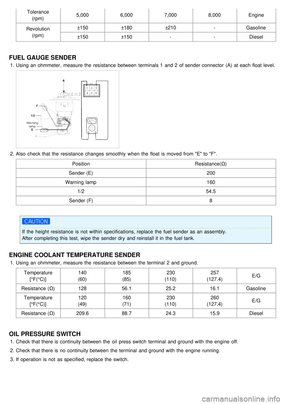
FUEL GAUGE SENDER
1.Using an ohmmeter, measure the resistance between terminals 1 and 2 of sender connector (A) at each float level.
2.Also check that the resistance changes smoothly when the float is moved from "E" to "F".
Position Resistance(Ω)
Sender (E) 200
Warning lamp 160
1/2 54.5
Sender (F) 8
If the height resistance is not within specifications, replace the fuel sender as an assembly.
After completing this test, wipe the sender dry and reinstall it in the fuel tank.
ENGINE COOLANT TEMPERATURE SENDER
1.Using an ohmmeter, measure the resistance between the terminal 2 and ground.
Temperature[°F(°C)] 140
(60) 185
(85) 230
(110) 257
(127.4) E/G
Resistance (Ω) 12856.1 25.216.1Gasoline
Temperature [°F(°C)] 120
(49) 160
(71) 230
(110) 260
(127.4) E/G
Resistance (Ω) 209.688.724.315.9Diesel
OIL PRESSURE SWITCH
1.Check that there is continuity between the oil press switch terminal and ground with the engine off.
2. Check that there is no continuity between the terminal and ground with the engine running.
3. If operation is not as specified, replace the switch.