Page 113 of 1575

THERMOSTAT
1.Immerse the thermostat in water and gradually heat water.
2.Check the valve opening temperature.
Valve opening temperature : 82°C (177°F)
Full opening temperature : 95°C (205°F)
If the valve opening temperature is not as specified, replace the thermostat.
3. Check the valve lift.
Valve lift : Min. 10mm (0.4in.) at 95°C (205°F)
If the valve lift is not as specified, replace the thermostat.
ENGINE COOLANT REFILLING AND BLEEDING
Never remove the radiator cap when the engine is hot. Serious scalding could be caused by hot fluid under high
pressure escaping from the radiator.
When pouring engine coolant, be sure to shut the relay box lid and not to let coolant spill on the electrical parts or
the paint. If any coolant spills, rinse it off immediately.
1. Make sure the engine and radiator are cool to the touch.
2. Open the radiator cap.
3. Loosen the drain plug, and drain the coolant.
4. Tighten the radiator drain plug securely.
5. Remove, drain and clean the reservoir tank.
6. Fill water slowly through the radiator cap. Push the upper/lower hoses of the radiator so as to bleed air easily.
7. Warm the engine until the cooling fan operates 2~3 times.
Accelerate the engine 2~3 times without load.
8. Wait until the engine is cold.
9. Repeat the steps 1~8 until the water drained is clean.
10. Fill fluid mixture with coolant and water(4 : 6) slowly through the radiator cap. Push the upper/lower hoses of the
radiator so as to bleed air easily.
11. Start the engine and run so coolant circulates.
When the cooling fan operates and coolant circulates, refill coolant through the radiator cap.
12. Repeat 11 until the cooling fan cycles 3 ~ 5 times and bleed air sufficiently out of the cooling system.
Page 114 of 1575
13.Install the radiator cap and fill the reservoir tank to the "MAX"(or "F") line with coolant.
14. Run the vehicle under idle until the cooling fan operates 2 ~ 3 times.
15. Stop the engine and wait until coolant gets cool.
16. Repeat 10 to 15 until the coolant level doesn't fall any more, bleeding air out of the cooling system.
Check the coolant level again in the reservoir tank for 2 ~ 3 days after replacing coolant.
CAP TESTING
1.Remove the radiator cap, wet its seal with engine coolant, and install it to a pressure tester.
2.Apply a pressure of 93 ~ 123kPa (0.95 ~ 1.25kgf/cm², 14 ~ 19psi).
3. Check for a drop in pressure.
4. If the pressure drops, replace the cap.
Page 230 of 1575

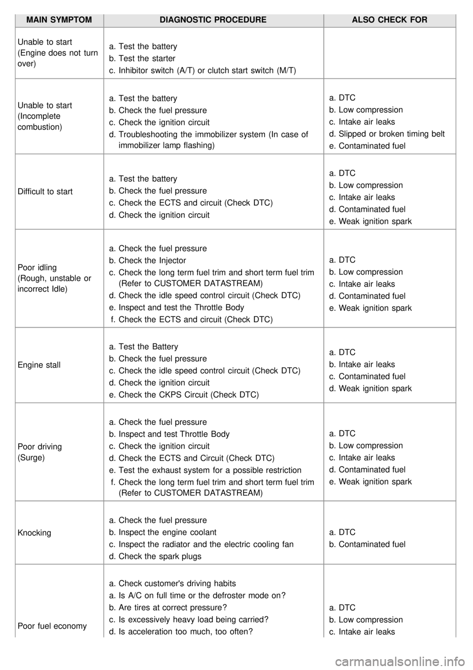
MAIN SYMPTOMDIAGNOSTIC PROCEDURE ALSO CHECK FOR
Unable to start
(Engine does not turn
over) a.
Test the battery
b. Test the starter
c. Inhibitor switch (A/T) or clutch start switch (M/T)
Unable to start
(Incomplete
combustion) a.
Test the battery
b. Check the fuel pressure
c. Check the ignition circuit
d. Troubleshooting the immobilizer system (In case of
immobilizer lamp flashing) a.
DTC
b. Low compression
c. Intake air leaks
d. Slipped or broken timing belt
e. Contaminated fuel
Difficult to start a.
Test the battery
b. Check the fuel pressure
c. Check the ECTS and circuit (Check DTC)
d. Check the ignition circuit a.
DTC
b. Low compression
c. Intake air leaks
d. Contaminated fuel
e. Weak ignition spark
Poor idling
(Rough, unstable or
incorrect Idle) a.
Check the fuel pressure
b. Check the Injector
c. Check the long term fuel trim and short term fuel trim
(Refer to CUSTOMER DATASTREAM)
d. Check the idle speed control circuit (Check DTC)
e. Inspect and test the Throttle Body
f. Check the ECTS and circuit (Check DTC) a.
DTC
b. Low compression
c. Intake air leaks
d. Contaminated fuel
e. Weak ignition spark
Engine stall a.
Test the Battery
b. Check the fuel pressure
c. Check the idle speed control circuit (Check DTC)
d. Check the ignition circuit
e. Check the CKPS Circuit (Check DTC) a.
DTC
b. Intake air leaks
c. Contaminated fuel
d. Weak ignition spark
Poor driving
(Surge) a.
Check the fuel pressure
b. Inspect and test Throttle Body
c. Check the ignition circuit
d. Check the ECTS and Circuit (Check DTC)
e. Test the exhaust system for a possible restriction
f. Check the long term fuel trim and short term fuel trim
(Refer to CUSTOMER DATASTREAM) a.
DTC
b. Low compression
c. Intake air leaks
d. Contaminated fuel
e. Weak ignition spark
Knocking a.
Check the fuel pressure
b. Inspect the engine coolant
c. Inspect the radiator and the electric cooling fan
d. Check the spark plugs a.
DTC
b. Contaminated fuel
Poor fuel economy a.
Check customer's driving habits
a. Is A/C on full time or the defroster mode on?
b. Are tires at correct pressure?
c. Is excessively heavy load being carried?
d. Is acceleration too much, too often? a.
DTC
b. Low compression
c. Intake air leaks
Page 372 of 1575

REPLACEMENT
If you have a fluid changer, use this changer to replace the fluid. If you do not, replace it using the following
procedure.1. Disconnect the hose which connects the transmission and the oil cooler which is within the radiator only in 2.4L
engine(3.3L- the oil cooler is separated).
2. Start the engine and let the fluid drain out.
Running conditions : "N" range with engine idling.
The engine should be stopped within one minute after it is started. If the fluid has all drained out before then,
the engine should be stopped at that point.
3. Romove the drain plug(A) from the bottom of the transmission case to drain the fluid.
4.Install the drain plug via the gasket, and tighten it to the specified torque.
TORQUE :
40~50Nm (4.0~5.0 kgf.m, 29~36 lb - ft)
5. Pour the new fluid in through the oil filler tube.
Stop pouring if the full volume of fluid cannot be poured in.
6. Repeat the procedure in step (2).
Check the old fluid for contamination. If it has been contaminated, repeat the steps (5) and (6).
7. Pour the new fluid in through the oil filler tube.
8. Reconnect the hose which was disconnected in step (1) above and firmly replace the oil level gauge.(In case of
this "replace", this means after wiping off any dirt around the oil level gauge, insert it into the filler tube.)
9. Start the engine and run it at idle for 1~2 minutes.
10. Move the select lever through all positions, and then move it to the "N" position.
11. Drive the vehicle until the fluid temperature rises to the normal temperature (70~80°C), and then check the fluid
level again. The fluid level must be at the HOT mark.
12. Firmly insert the oil level gauge(A) into the oil filler tube.
Page 385 of 1575

29.Lifting the vehicle up and lowering the jack slowly, remove the transaxle assembly.
INSTALLATION
Installation is in the reverse order of removal.
Perform the following :
a. Adjust the shift cable.
b. Refill the transaxle with fluid.
c. Refill the radiator with engine coolant.
d. Bleed air from the cooling system with the heater valve open.
e. Clean the battery posts and cable terminals with sandpaper, assemble them, and apply grease to prevent
corrosion.
1. Lowering the vehicle or lifting up a jack, install the transaxle assembly.
2. Tighten the transaxle lower mounting bolts (B- 4EA).
TORQUE:
65~85 Nm(6.5~8.5 kgf.m, 47.0~61.5 lb - ft)
3. Install the drive plate bolts (A) by turning the timing gear.
TORQUE:
46~53 Nm(4.6~5.3 kgf.m, 33.3~38.3 lb - ft)
4.After removing a jack, insert the drive shafts. (see DS group)
5. Install the sub frame. (see SS group).
6. Tighten the roll stopper mounting bolts.
TORQUE:
90~110 Nm(9~11 kgf.m, 65.1~79.5 lb - ft)
7. Connect the lower arm, the tie rod end ball joint, the stabilizer bar link to the front knuckle. (see SS group)
Page 668 of 1575

2007 > 2.7L V6 GASOLINE >
INSPECTION
1.Check the condenser fins for clogging and damage. If clogged, clean them with water, and blow them with
compressed air. If bent, gently bend them using a screwdriver or pliers.
2. Check the condenser connections for leakage, and repair or replace it, if required.
REPLACEMENT
CONDENSER ASSEMBLY
1. Recover the refrigerant with a recovery/ recycling/ charging station (Refer to HA - 8).
2. Disconnect the negative ( - ) battery terminal.
3. Remove the radiator. (Refer to EM group)
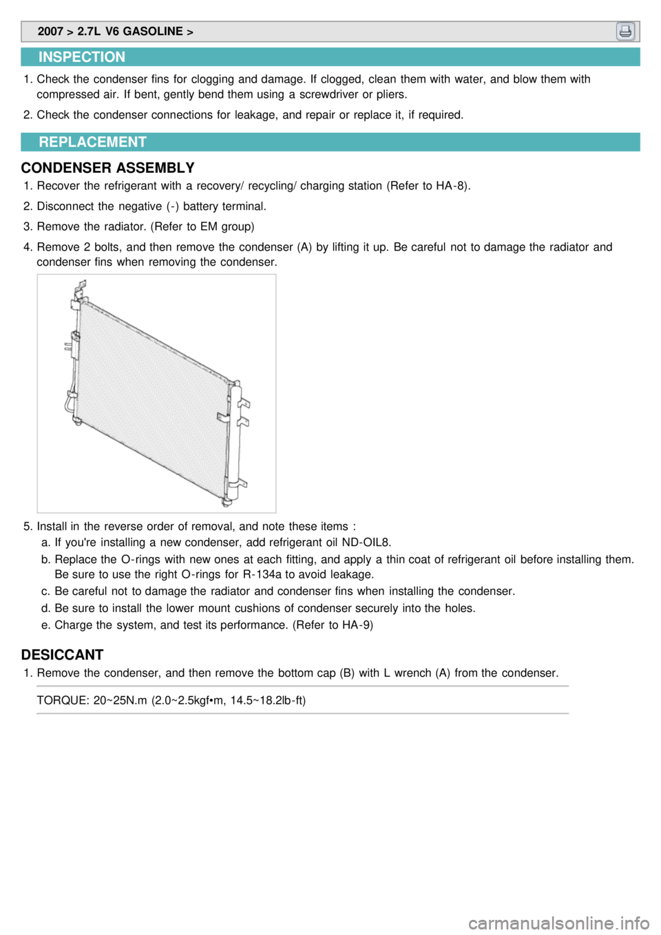
4. Remove 2 bolts, and then remove the condenser (A) by lifting it up. Be careful not to damage the radiator and
condenser fins when removing the condenser.
5.Install in the reverse order of removal, and note these items :
a. If you're installing a new condenser, add refrigerant oil ND- OIL8.
b. Replace the O - rings with new ones at each fitting, and apply a thin coat of refrigerant oil before installing them.
Be sure to use the right O - rings for R- 134a to avoid leakage.
c. Be careful not to damage the radiator and condenser fins when installing the condenser.
d. Be sure to install the lower mount cushions of condenser securely into the holes.
e. Charge the system, and test its performance. (Refer to HA - 9)
DESICCANT
1.Remove the condenser, and then remove the bottom cap (B) with L wrench (A) from the condenser.
TORQUE: 20~25N.m (2.0~2.5kgf•m, 14.5~18.2lb - ft)
Page 669 of 1575
2.Remove the desiccant (A) from condenser using a long nose plier. Check for crumbled desiccant and clogged
bottom cap filter.
3.Apply air conditioning compressor oil along the O - rings and threads of the new bottom cap.
4. Insert the new desiccant into the receiver drier tank. The desiccant must be sealed in vacuum before it is exposed
to air for use.
5. Install the new bottom cap to the condenser.
a.Always replace the desiccant and bottom cap at the same time.
b. Replace the O - rings with new ones at each fitting, and apply a thin coat of refrigerant oil before installing
them. Be sure to use the right O - rings for R- 134a to avoid leakage.
c. Be careful not to damage the radiator and condenser fins when installing the condenser.
d. Be sure to install the lower mount cushions of condenser securely into the holes.
e. Charge the system, and test its performance. (Refer to HA - 10)
Page 701 of 1575
2007 > 2.7L V6 GASOLINE >
DESCRIPTION
1.A.Q.S is located at center support in front of the engine radiator, and detects hazardous elements in ambient air
providing output signal to control.
2. It will detect sulfurous acid gas, carbon dioxide, carbon monoxide, hydrocarbon and allergen.