2007 KIA CARNIVAL change time
[x] Cancel search: change timePage 1234 of 1575
CLOSE signal.
b. RAM will pass this signal to LH PSD and RH PSD then the burglar alarm state is decided depending on the
vehicle condition.
f. PTG open/close
a. Only with the information received by RKE, the burglar alarm system cannot distinguish the OPEN signal from
CLOSE signal.
b. RAM will pass this signal to PTG module then the burglar alarm state is decided depending on the vehicle
condition.
g. Panic by key fob
a. Whenever this signal is received, the PANIC function is activated (unless the system is already in an ALARM
state).
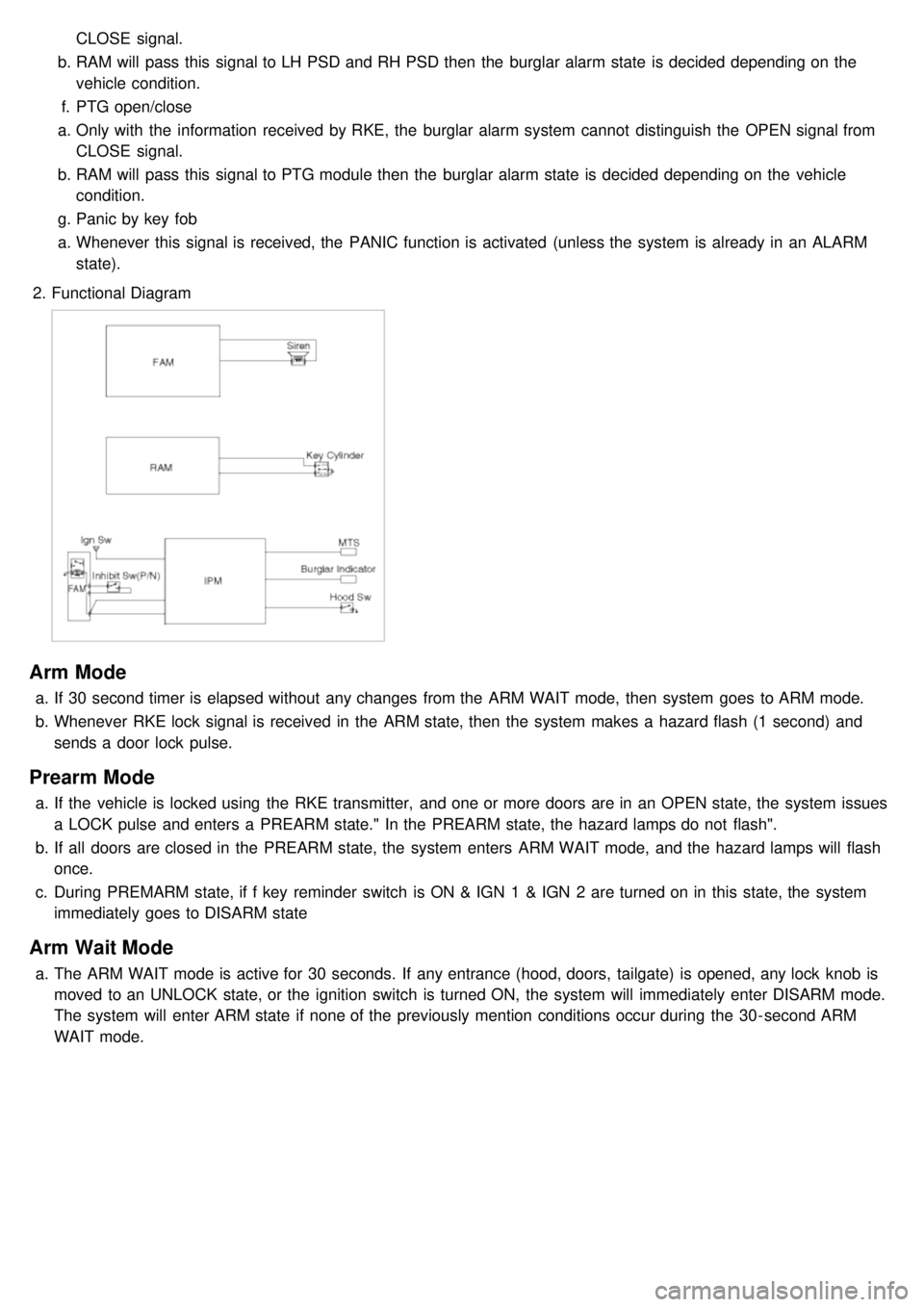
2. Functional Diagram
Arm Mode
a.If 30 second timer is elapsed without any changes from the ARM WAIT mode, then system goes to ARM mode.
b. Whenever RKE lock signal is received in the ARM state, then the system makes a hazard flash (1 second) and
sends a door lock pulse.
Prearm Mode
a.If the vehicle is locked using the RKE transmitter, and one or more doors are in an OPEN state, the system issues
a LOCK pulse and enters a PREARM state." In the PREARM state, the hazard lamps do not flash".
b. If all doors are closed in the PREARM state, the system enters ARM WAIT mode, and the hazard lamps will flash
once.
c. During PREMARM state, if f key reminder switch is ON & IGN 1 & IGN 2 are turned on in this state, the system
immediately goes to DISARM state
Arm Wait Mode
a.The ARM WAIT mode is active for 30 seconds. If any entrance (hood, doors, tailgate) is opened, any lock knob is
moved to an UNLOCK state, or the ignition switch is turned ON, the system will immediately enter DISARM mode.
The system will enter ARM state if none of the previously mention conditions occur during the 30- second ARM
WAIT mode.
Page 1260 of 1575
4.Operation control
a. Prioritization of operations
Motor starting is delayed for 100ms respectively in case of auto control to prevent rush current from overlap
when motors are running, and it follows the following order.
Slide > recline > front height > rear height > adjust pedal
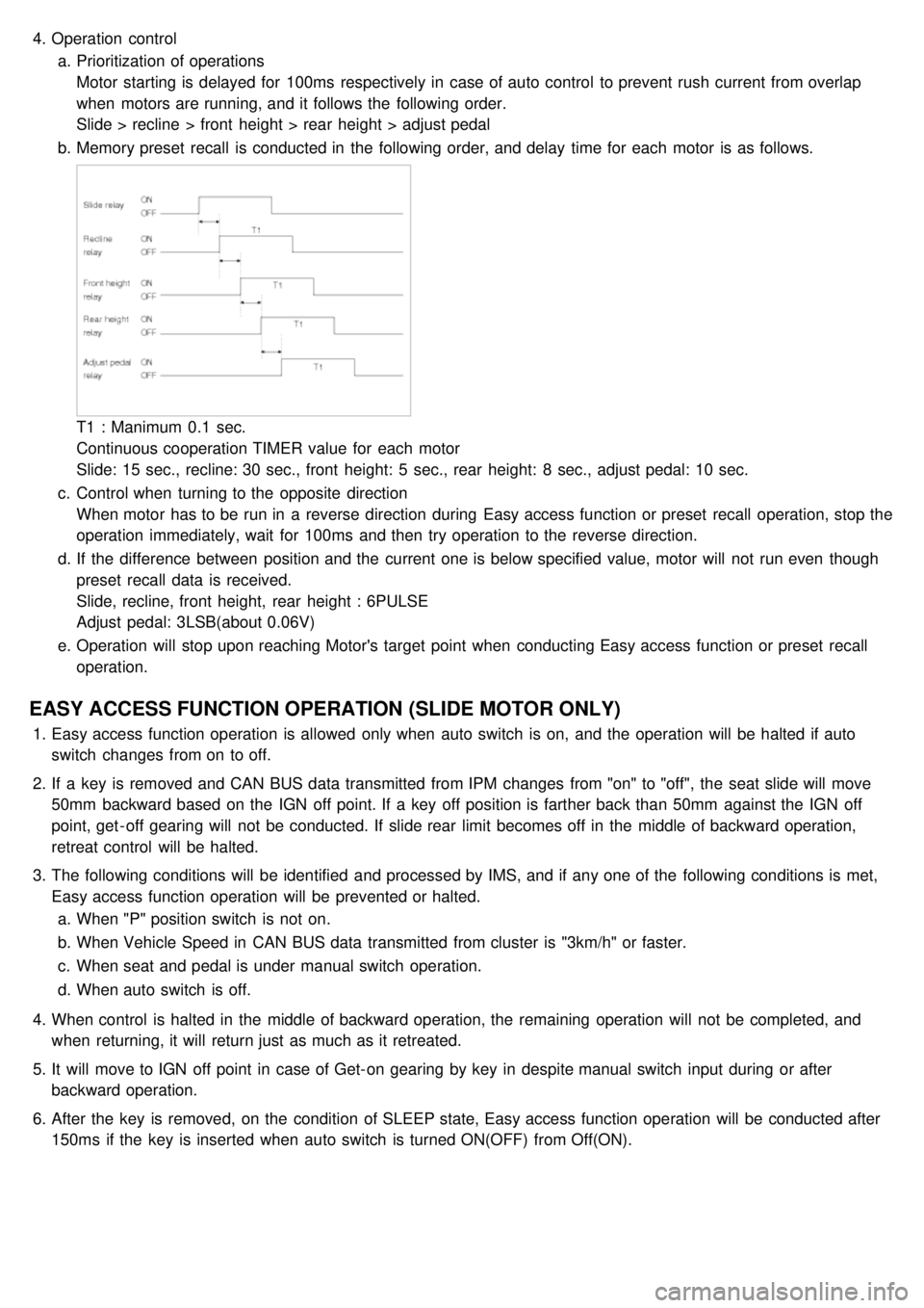
b. Memory preset recall is conducted in the following order, and delay time for each motor is as follows.
T1 : Manimum 0.1 sec.
Continuous cooperation TIMER value for each motor
Slide: 15 sec., recline: 30 sec., front height: 5 sec., rear height: 8 sec., adjust pedal: 10 sec.
c. Control when turning to the opposite direction
When motor has to be run in a reverse direction during Easy access function or preset recall operation, stop the
operation immediately, wait for 100ms and then try operation to the reverse direction.
d. If the difference between position and the current one is below specified value, motor will not run even though
preset recall data is received.
Slide, recline, front height, rear height : 6PULSE
Adjust pedal: 3LSB(about 0.06V)
e. Operation will stop upon reaching Motor's target point when conducting Easy access function or preset recall
operation.
EASY ACCESS FUNCTION OPERATION (SLIDE MOTOR ONLY)
1.Easy access function operation is allowed only when auto switch is on, and the operation will be halted if auto
switch changes from on to off.
2. If a key is removed and CAN BUS data transmitted from IPM changes from "on" to "off", the seat slide will move
50mm backward based on the IGN off point. If a key off position is farther back than 50mm against the IGN off
point, get - off gearing will not be conducted. If slide rear limit becomes off in the middle of backward operation,
retreat control will be halted.
3. The following conditions will be identified and processed by IMS, and if any one of the following conditions is met,
Easy access function operation will be prevented or halted.
a. When "P" position switch is not on.
b. When Vehicle Speed in CAN BUS data transmitted from cluster is "3km/h" or faster.
c. When seat and pedal is under manual switch operation.
d. When auto switch is off.
4. When control is halted in the middle of backward operation, the remaining operation will not be completed, and
when returning, it will return just as much as it retreated.
5. It will move to IGN off point in case of Get- on gearing by key in despite manual switch input during or after
backward operation.
6. After the key is removed, on the condition of SLEEP state, Easy access function operation will be conducted after
150ms if the key is inserted when auto switch is turned ON(OFF) from Off(ON).
Page 1262 of 1575
Error conditionBelow 6 pulses in 2 sec. Below 6 pulses in 1 sec.
Prerequisite FR/RR limit SW on Limit setting complete
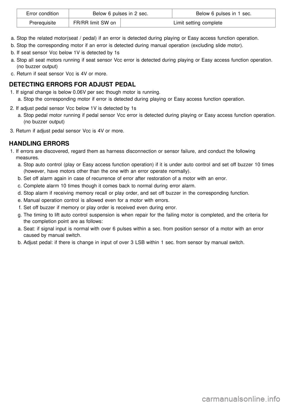
a. Stop the related motor(seat / pedal) if an error is detected during playing or Easy access function operation.
b. Stop the corresponding motor if an error is detected during manual operation (excluding slide motor).
b. If seat sensor Vcc below 1V is detected by 1s
a. Stop all seat motors running if seat sensor Vcc error is detected during playing or Easy access function operation.
(no buzzer output)
c. Return if seat sensor Vcc is 4V or more.
DETECTING ERRORS FOR ADJUST PEDAL
1.If signal change is below 0.06V per sec though motor is running.
a. Stop the corresponding motor if error is detected during playing or Easy access function operation.
2. If adjust pedal sensor Vcc below 1V is detected by 1s
a. Stop pedal motor running if pedal sensor Vcc error is detected during playing or Easy access function operation.
(no buzzer output)
3. Return if adjust pedal sensor Vcc is 4V or more.
HANDLING ERRORS
1.If errors are discovered, regard them as harness disconnection or sensor failure, and conduct the following
measures.
a. Stop auto control (play or Easy access function operation) if it is under auto control and set off buzzer 10 times
(however, have motors other than the one with an error operate normally).
b. Set off alarm again in case of recurrence of error after restoration of a motor with an error.
c. Complete alarm 10 times though it comes back to normal during error alarm.
d. Stop alarm if receiving memory recall or play order, and set off buzzer in the corresponding function.
e. Manual operation control is allowed even for a motor with errors.
f. Set off buzzer if memory or play order is received even during error.
g. The timing to lift auto control suspension is when repair for the failing motor is completed, and the criteria for
the completion point are as follows:
a. Seat: if signal input is normal with over 6 pulses within a sec. from position sensor of a motor with an error
caused by manual switch.
b. Adjust pedal: if there is change in input of over 3 LSB within 1 sec. from sensor by manual switch.
Page 1415 of 1575
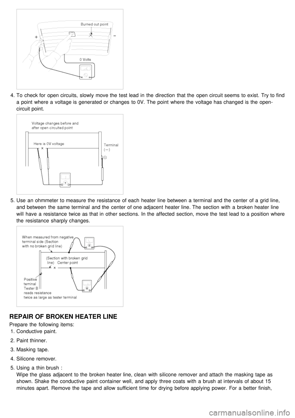
4.To check for open circuits, slowly move the test lead in the direction that the open circuit seems to exist. Try to find
a point where a voltage is generated or changes to 0V. The point where the voltage has changed is the open-
circuit point.
5.Use an ohmmeter to measure the resistance of each heater line between a terminal and the center of a grid line,
and between the same terminal and the center of one adjacent heater line. The section with a broken heater line
will have a resistance twice as that in other sections. In the affected section, move the test lead to a position where
the resistance sharply changes.
REPAIR OF BROKEN HEATER LINE
Prepare the following items:
1. Conductive paint.
2. Paint thinner.
3. Masking tape.
4. Silicone remover.
5. Using a thin brush :
Wipe the glass adjacent to the broken heater line, clean with silicone remover and attach the masking tape as
shown. Shake the conductive paint container well, and apply three coats with a brush at intervals of about 15
minutes apart. Remove the tape and allow sufficient time for drying before applying power. For a better finish,
scrape away excess deposits with a knife after the paint has completely dried. (Allow 24 hours).
Page 1506 of 1575
2007 > 2.7L V6 GASOLINE >
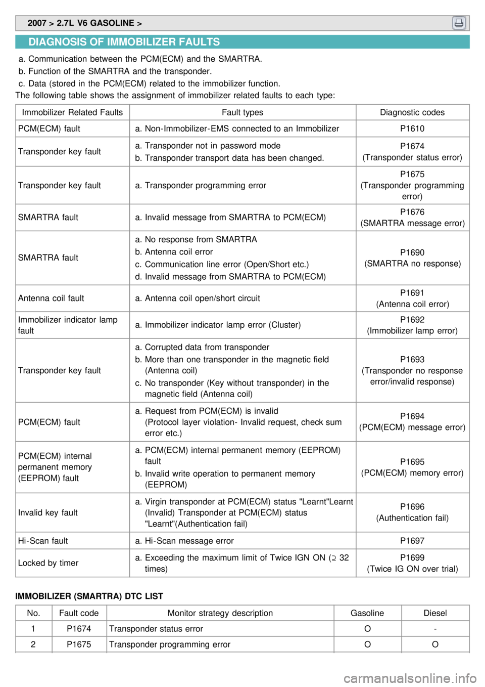
DIAGNOSIS OF IMMOBILIZER FAULTS
a.Communication between the PCM(ECM) and the SMARTRA.
b. Function of the SMARTRA and the transponder.
c. Data (stored in the PCM(ECM) related to the immobilizer function.
The following table shows the assignment of immobilizer related faults to each type:
Immobilizer Related Faults Fault typesDiagnostic codes
PCM(ECM) fault a.Non- Immobilizer- EMS connected to an Immobilizer P1610
Transponder key fault a.
Transponder not in password mode
b. Transponder transport data has been changed. P1674
(Transponder status error)
Transponder key fault a.Transponder programming error P1675
(Transponder programming error)
SMARTRA fault a.Invalid message from SMARTRA to PCM(ECM) P1676
(SMARTRA message error)
SMARTRA fault a.
No response from SMARTRA
b. Antenna coil error
c. Communication line error (Open/Short etc.)
d. Invalid message from SMARTRA to PCM(ECM) P1690
(SMARTRA no response)
Antenna coil fault a.Antenna coil open/short circuit P1691
(Antenna coil error)
Immobilizer indicator lamp
fault a.
Immobilizer indicator lamp error (Cluster) P1692
(Immobilizer lamp error)
Transponder key fault a.
Corrupted data from transponder
b. More than one transponder in the magnetic field
(Antenna coil)
c. No transponder (Key without transponder) in the
magnetic field (Antenna coil) P1693
(Transponder no response error/invalid response)
PCM(ECM) fault a.
Request from PCM(ECM) is invalid
(Protocol layer violation- Invalid request, check sum
error etc.) P1694
(PCM(ECM) message error)
PCM(ECM) internal
permanent memory
(EEPROM) fault a.
PCM(ECM) internal permanent memory (EEPROM)
fault
b. Invalid write operation to permanent memory
(EEPROM) P1695
(PCM(ECM) memory error)
Invalid key fault a.
Virgin transponder at PCM(ECM) status "Learnt"Learnt
(Invalid) Transponder at PCM(ECM) status
"Learnt"(Authentication fail) P1696
(Authentication fail)
Hi - Scan fault a.Hi - Scan message error P1697
Locked by timer a.
Exceeding the maximum limit of Twice IGN ON ( ⊇ 32
times) P1699
(Twice IG ON over trial)
IMMOBILIZER (SMARTRA) DTC LIST No. Fault code Monitor strategy description GasolineDiesel
1 P1674 Transponder status error O-
2 P1675 Transponder programming error OO
Page 1508 of 1575
2007 > 2.7L V6 GASOLINE >
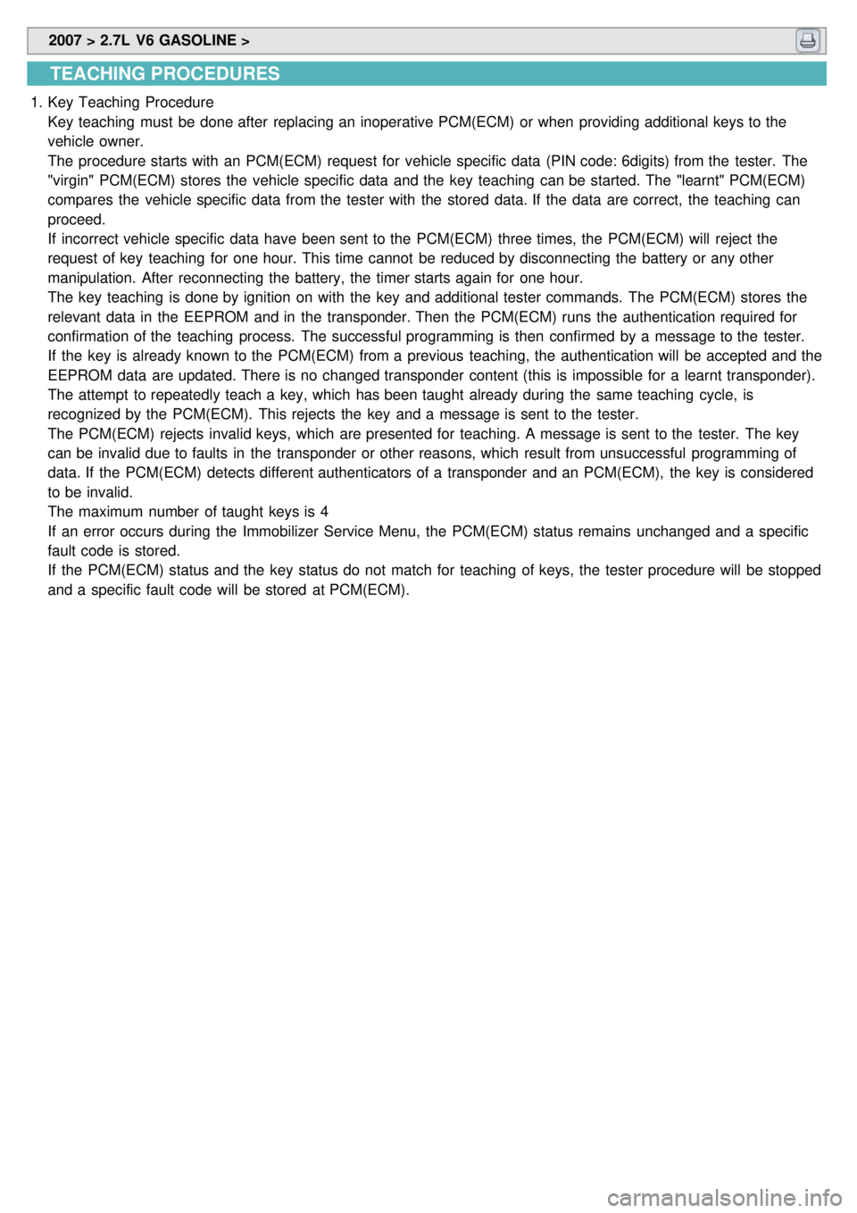
TEACHING PROCEDURES
1.Key Teaching Procedure
Key teaching must be done after replacing an inoperative PCM(ECM) or when providing additional keys to the
vehicle owner.
The procedure starts with an PCM(ECM) request for vehicle specific data (PIN code: 6digits) from the tester. The
"virgin" PCM(ECM) stores the vehicle specific data and the key teaching can be started. The "learnt" PCM(ECM)
compares the vehicle specific data from the tester with the stored data. If the data are correct, the teaching can
proceed.
If incorrect vehicle specific data have been sent to the PCM(ECM) three times, the PCM(ECM) will reject the
request of key teaching for one hour. This time cannot be reduced by disconnecting the battery or any other
manipulation. After reconnecting the battery, the timer starts again for one hour.
The key teaching is done by ignition on with the key and additional tester commands. The PCM(ECM) stores the
relevant data in the EEPROM and in the transponder. Then the PCM(ECM) runs the authentication required for
confirmation of the teaching process. The successful programming is then confirmed by a message to the tester.
If the key is already known to the PCM(ECM) from a previous teaching, the authentication will be accepted and the
EEPROM data are updated. There is no changed transponder content (this is impossible for a learnt transponder).
The attempt to repeatedly teach a key, which has been taught already during the same teaching cycle, is
recognized by the PCM(ECM). This rejects the key and a message is sent to the tester.
The PCM(ECM) rejects invalid keys, which are presented for teaching. A message is sent to the tester. The key
can be invalid due to faults in the transponder or other reasons, which result from unsuccessful programming of
data. If the PCM(ECM) detects different authenticators of a transponder and an PCM(ECM), the key is considered
to be invalid.
The maximum number of taught keys is 4
If an error occurs during the Immobilizer Service Menu, the PCM(ECM) status remains unchanged and a specific
fault code is stored.
If the PCM(ECM) status and the key status do not match for teaching of keys, the tester procedure will be stopped
and a specific fault code will be stored at PCM(ECM).
Page 1512 of 1575
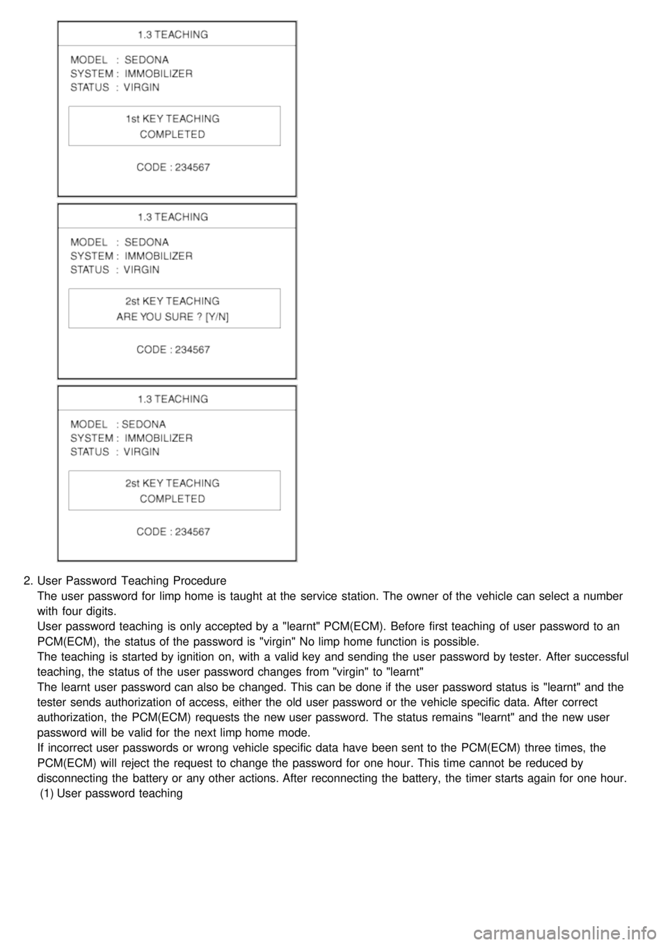
2.User Password Teaching Procedure
The user password for limp home is taught at the service station. The owner of the vehicle can select a number
with four digits.
User password teaching is only accepted by a "learnt" PCM(ECM). Before first teaching of user password to an
PCM(ECM), the status of the password is "virgin" No limp home function is possible.
The teaching is started by ignition on, with a valid key and sending the user password by tester. After successful
teaching, the status of the user password changes from "virgin" to "learnt"
The learnt user password can also be changed. This can be done if the user password status is "learnt" and the
tester sends authorization of access, either the old user password or the vehicle specific data. After correct
authorization, the PCM(ECM) requests the new user password. The status remains "learnt" and the new user
password will be valid for the next limp home mode.
If incorrect user passwords or wrong vehicle specific data have been sent to the PCM(ECM) three times, the
PCM(ECM) will reject the request to change the password for one hour. This time cannot be reduced by
disconnecting the battery or any other actions. After reconnecting the battery, the timer starts again for one hour.
(1) User password teaching
Page 1526 of 1575
2007 > 2.7L V6 GASOLINE >
DESCRIPTION
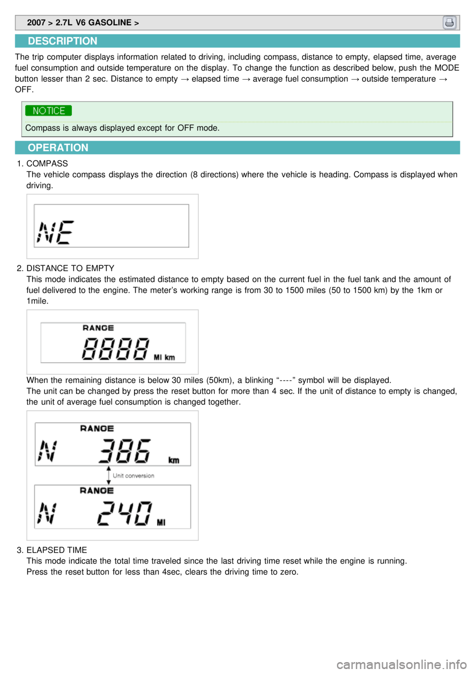
The trip computer displays information related to driving, including compass, distance to empty, elapsed time, average
fuel consumption and outside temperature on the display. To change the function as described below, push the MODE
button lesser than 2 sec. Distance to empty → elapsed time → average fuel consumption → outside temperature →
OFF.
Compass is always displayed except for OFF mode.
OPERATION
1. COMPASS
The vehicle compass displays the direction (8 directions) where the vehicle is heading. Compass is displayed when
driving.
2.DISTANCE TO EMPTY
This mode indicates the estimated distance to empty based on the current fuel in the fuel tank and the amount of
fuel delivered to the engine. The meter’s working range is from 30 to 1500 miles (50 to 1500 km) by the 1km or
1mile.
When the remaining distance is below 30 miles (50km), a blinking “ - - - - ” symbol will be displayed.
The unit can be changed by press the reset button for more than 4 sec. If the unit of distance to empty is changed,
the unit of average fuel consumption is changed together.
3.ELAPSED TIME
This mode indicate the total time traveled since the last driving time reset while the engine is running.
Press the reset button for less than 4sec, clears the driving time to zero.