Page 464 of 1575
(B) on the driveshaft splines (C).
8.Add the specified grease to the joint(UTJ) boot as mush as wiped away at inspection.
9. Install the boots.
10. To control the air in the UTJ boot, keep the specified distance between the boot bands when they are tightened.
Standard value [A]
Items Standard (A) mm(in)
LH RH
2.9 Diesel M/T 505.4 (19.90)466.8 (18.38)
2.9 Diesel A/T 507.5 (19.98)466.9 (18.38)
3.8 Gasoline A/T 557.1 (21.93)570.7 (22.47)
11. Install both sides of the boot bands by using SST (09495- 39100).
Page 504 of 1575

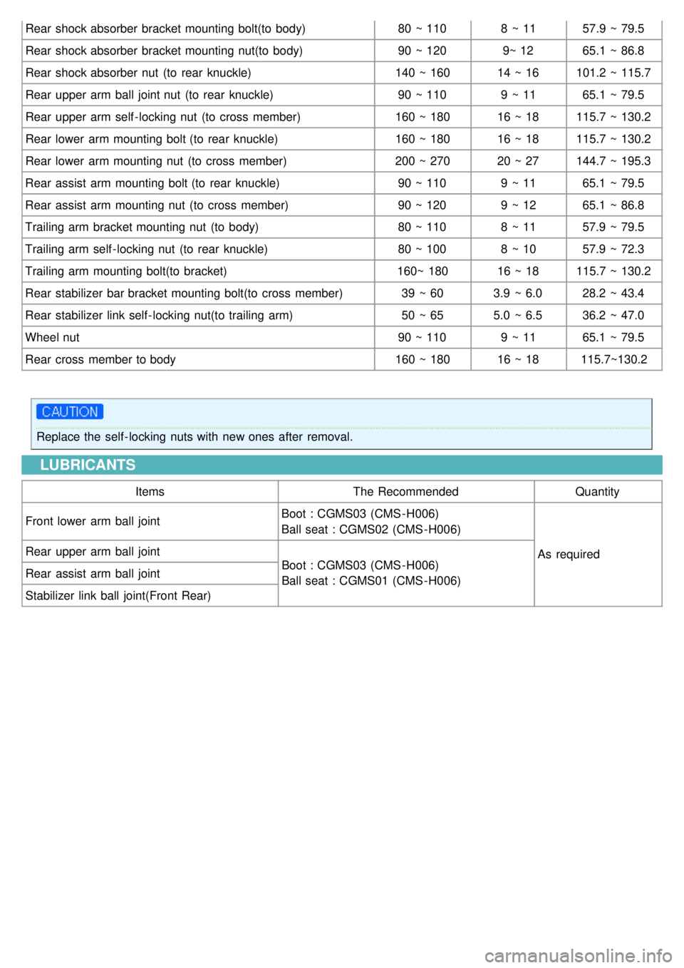
Rear shock absorber bracket mounting bolt(to body)80 ~ 1108 ~ 1157.9 ~ 79.5
Rear shock absorber bracket mounting nut(to body) 90 ~ 1209~ 1265.1 ~ 86.8
Rear shock absorber nut (to rear knuckle) 140 ~ 16014 ~ 16101.2 ~ 115.7
Rear upper arm ball joint nut (to rear knuckle) 90 ~ 1109 ~ 1165.1 ~ 79.5
Rear upper arm self - locking nut (to cross member) 160 ~ 18016 ~ 18115.7 ~ 130.2
Rear lower arm mounting bolt (to rear knuckle) 160 ~ 18016 ~ 18115.7 ~ 130.2
Rear lower arm mounting nut (to cross member) 200 ~ 27020 ~ 27144.7 ~ 195.3
Rear assist arm mounting bolt (to rear knuckle) 90 ~ 1109 ~ 1165.1 ~ 79.5
Rear assist arm mounting nut (to cross member) 90 ~ 1209 ~ 1265.1 ~ 86.8
Trailing arm bracket mounting nut (to body) 80 ~ 1108 ~ 1157.9 ~ 79.5
Trailing arm self - locking nut (to rear knuckle) 80 ~ 1008 ~ 1057.9 ~ 72.3
Trailing arm mounting bolt(to bracket) 160~ 18016 ~ 18115.7 ~ 130.2
Rear stabilizer bar bracket mounting bolt(to cross member) 39 ~ 603.9 ~ 6.028.2 ~ 43.4
Rear stabilizer link self - locking nut(to trailing arm) 50 ~ 655.0 ~ 6.536.2 ~ 47.0
Wheel nut 90 ~ 1109 ~ 1165.1 ~ 79.5
Rear cross member to body 160 ~ 18016 ~ 18115.7~130.2
Replace the self - locking nuts with new ones after removal.
LUBRICANTS
Items The Recommended Quantity
Front lower arm ball joint Boot : CGMS03 (CMS - H006)
Ball seat : CGMS02 (CMS - H006)
As required
Rear upper arm ball joint
Boot : CGMS03 (CMS - H006)
Ball seat : CGMS01 (CMS - H006)
Rear assist arm ball joint
Stabilizer link ball joint(Front Rear)
Page 609 of 1575
(4)Check for oil seal ring damage or wear.
(5) Check for oil seal damage or wear.
2.Pinion valve
(1) Check for pinion gear tooth face damage or wear.
(2) Check for oil seal contact surface damage.
(3) Check for seal ring damage or wear.
(4) Check for oil seal damage or wear.
3.Bearing
(1) Check for seizure or abnormal noise during abearing rotation.
(2) Check for excessive play.
(3) Check for missing needle bearing rollers.
4. Others
(1) Check for damage of the rack housing cylinder bore.
(2) Check for boot damage, cracking or aging.
REASSEMBLY
1.Apply the specified fluid to the entire surface of the rack oil seal.
Recommended fluid : PSF - 3
2. Install the backup washer and oil seal (A) to the specified position in the rack housing.
Page 867 of 1575

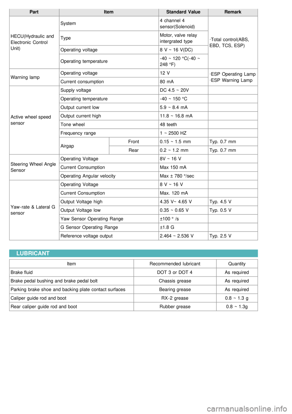
PartItemStandard ValueRemark
HECU(Hydraulic and
Electronic Control
Unit) System
4 channel 4
sensor(Solenoid)
·Total control(ABS,
EBD, TCS, ESP)
Type
Motor, valve relay
intergrated type
Operating voltage 8 V ~ 16 V(DC)
Operating temperature - 40 ~ 120 °C(- 40 ~
248 °F)
Warning lamp Operating voltage
12 V
·ESP Operating Lamp
·ESP Warning Lamp
Current consumption 80 mA
Active wheel speed
sensor Supply voltage
DC 4.5 ~ 20V
Operating temperature - 40 ~ 150 °C
Output current low 5.9 ~ 8.4 mA
Output current high 11.8 ~ 16.8 mA
Tone wheel 48 teeth
Frequency range 1 ~ 2500 HZ
Airgap Front
0.15 ~ 1.5 mm Typ. 0.7 mm
Rear 0.2 ~ 1.2 mm Typ. 0.7 mm
Steering Wheel Angle
Sensor Operating Voltage
8V ~ 16 V
Current Consumption Max 150 mA
Operating Angular velocity Max ± 780 °/sec
Yaw - rate & Lateral G
sensor Operating Voltage
8 V ~ 16 V
Current Consumption Max. 120 mA
Output Voltage high 4.35 V~ 4.65 VTyp. 4.5 V
Output Voltage low 0.35 ~ 0.65 VTyp. 0.5 V
Yaw Sensor Operating Range ±100 ° /s
G Sensor Operating Range ±1.8 G
Reference voltage output 2.464 ~ 2.536 VTyp. 2.5 V
LUBRICANT
Item Recommended lubricantQuantity
Brake fluid DOT 3 or DOT 4As required
Brake pedal bushing and brake pedal bolt Chassis greaseAs required
Parking brake shoe and backing plate contact surfaces Bearing greaseAs required
Caliper guide rod and boot RX - 2 grease0.8 ~ 1.3 g
Rear caliper guide rod and boot Rubber grease0.8 ~ 1.3g
Page 869 of 1575

2007 > 2.7L V6 GASOLINE >
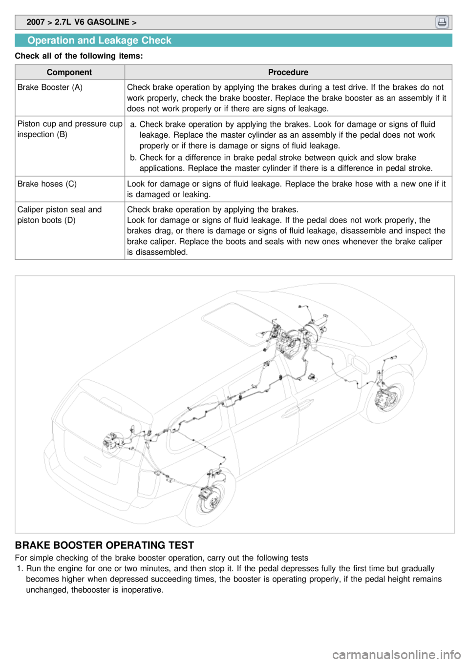
Operation and Leakage Check
Check all of the following items:
Component Procedure
Brake Booster (A) Check brake operation by applying the brakes during a test drive. If the brakes do not
work properly, check the brake booster. Replace the brake booster as an assembly if it
does not work properly or if there are signs of leakage.
Piston cup and pressure cup
inspection (B) a.
Check brake operation by applying the brakes. Look for damage or signs of fluid
leakage. Replace the master cylinder as an assembly if the pedal does not work
properly or if there is damage or signs of fluid leakage.
b. Check for a difference in brake pedal stroke between quick and slow brake
applications. Replace the master cylinder if there is a difference in pedal stroke.
Brake hoses (C) Look for damage or signs of fluid leakage. Replace the brake hose with a new one if it
is damaged or leaking.
Caliper piston seal and
piston boots (D) Check brake operation by applying the brakes.
Look for damage or signs of fluid leakage. If the pedal does not work properly, the
brakes drag, or there is damage or signs of fluid leakage, disassemble and inspect the
brake caliper. Replace the boots and seals with new ones whenever the brake caliper
is disassembled.
BRAKE BOOSTER OPERATING TEST
For simple checking of the brake booster operation, carry out the following tests
1. Run the engine for one or two minutes, and then stop it. If the pedal depresses fully the first time but gradually
becomes higher when depressed succeeding times, the booster is operating properly, if the pedal height remains
unchanged, thebooster is inoperative.
Page 900 of 1575
If you are reusing the pads, always reinstall the brake pads in their original positions to prevent a momentary
loss of braking efficiency.
3.Insert the piston in the cylinder using the special tool (09581- 11000).
4.Push in the piston (A) so that the caliper will fit over the pads. Make sure that the piston boot is in position to
prevent damaging it when pivoting the caliper down.
5. Being careful not to damage the pin boot, install the guide rod bolt (B) with the specified torque.
6.If caliper assembly was removed, install the brake hose to the caliper.
7. Refill the master cylinder reservoir to the MAX line.
8. Bleed the brake system.(Refer to 'Bleeding of ABS system')
9. Depress the brake pedal several times to make sure the brakes work, then test- drive.
Engagement of the brake may require a greater pedal stroke immediately after the brake pads have been
replaced as a set. Several applications of the brake will restore the normal pedal stroke.
Page 906 of 1575
4.Grease the piston boot to prevent from twisting.
5. Install the guide rod.
6. Install the cylinder assembly (A) to the disc plate.
Be careful not to damage the piston boot.
7.Install the guide rod bolt (B).
Tightening torque Nm(kgf.m,lb - ft) :
22 ~ 32 (2.2 ~ 3.2, 15.9 ~ 23.1)
INSPECTION
REAR BRAKE DISC THICKNESS CHECK
1. Remove all rust and contamination from the disc surface, and then measure the disc thickness at 8 points, al least,
of the same distance (5 mm(0.12 in)) from the brake disc outer circle.
Rear brake disc thickness
Standard value : 12.0 mm (0.47 in)
Limit : 10.4 mm (0.41 in)
2. Thickness variation should not exceed 0.01 mm(0.0004 in) (circumference) and 0.01 mm(0.0004 in) (radius) at any
directions.
3. If wear exceeds the limit, replace the discs and pad assembly for left and right of the vehicle.