Page 224 of 1575

during testing. An example would be if a problem appears only when the vehicle is cold but has not appeared when
warm. In this case, the technician should thoroughly make out a "CUSTOMER PROBLEM ANALYSIS SHEET" and
recreate (simulate) the environment and condition which occurred when the vehicle was having the issue.1. Clear Diagnostic Trouble Code (DTC).
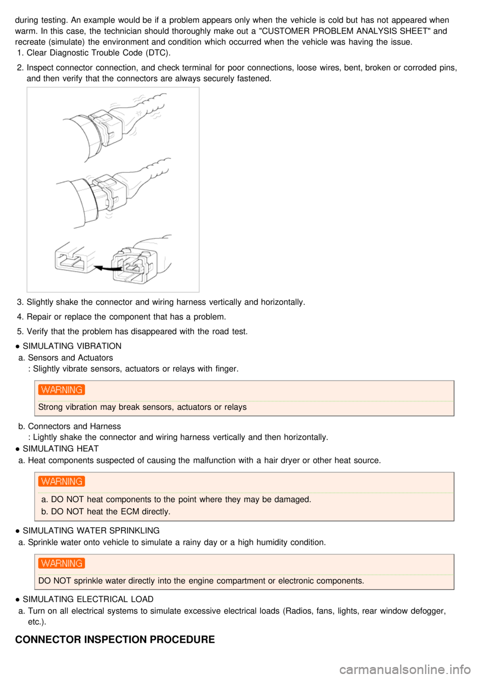
2. Inspect connector connection, and check terminal for poor connections, loose wires, bent, broken or corroded pins,
and then verify that the connectors are always securely fastened.
3.Slightly shake the connector and wiring harness vertically and horizontally.
4. Repair or replace the component that has a problem.
5. Verify that the problem has disappeared with the road test.
● SIMULATING VIBRATION
a. Sensors and Actuators
: Slightly vibrate sensors, actuators or relays with finger.
Strong vibration may break sensors, actuators or relays
b. Connectors and Harness
: Lightly shake the connector and wiring harness vertically and then horizontally.
● SIMULATING HEAT
a. Heat components suspected of causing the malfunction with a hair dryer or other heat source.
a.DO NOT heat components to the point where they may be damaged.
b. DO NOT heat the ECM directly.
● SIMULATING WATER SPRINKLING
a. Sprinkle water onto vehicle to simulate a rainy day or a high humidity condition.
DO NOT sprinkle water directly into the engine compartment or electronic components.
● SIMULATING ELECTRICAL LOAD
a. Turn on all electrical systems to simulate excessive electrical loads (Radios, fans, lights, rear window defogger,
etc.).
CONNECTOR INSPECTION PROCEDURE
Page 225 of 1575
1.Handling of Connector
a. Never pull on the wiring harness when disconnecting connectors.
b.When removing the connector with a lock, press or pull locking lever.
c.Listen for a click when locking connectors. This sound indicates that they are securely locked.
d.When a tester is used to check for continuity, or to measure voltage, always insert tester probe from wire
harness side.
Page 226 of 1575
e.Check waterproof connector terminals from the connector side. Waterproof connectors cannot be accessed from
harness side.
a.Use a fine wire to prevent damage to the terminal.
b. Do not damage the terminal when inserting the tester lead.
2. Checking Point for Connector
a. While the connector is connected:
Hold the connector, check connecting condition and locking efficiency.
b. When the connector is disconnected:
Check missed terminal, crimped terminal or broken core wire by slightly pulling the wire harness.
Visually check for rust, contamination, deformation and bend.
c. Check terminal tightening condition:
Insert a spare male terminal into a female terminal, and then check terminal tightening conditions.
d. Pull lightly on individual wires to ensure that each wire is secured in the terminal.
3.Repair Method of Connector Terminal
a. Clean the contact points using air gun and/or shop rag.
Page 227 of 1575

Never use sand paper when polishing the contact points, otherwise the contact point may be damaged.
b. In case of abnormal contact pressure, replace the female terminal.
WIRE HARNESS INSPECTION PROCEDURE
1.Before removing the wire harness, check the wire harness position and crimping in order to restore it correctly.
2. Check whether the wire harness is twisted, pulled or loosened.
3. Check whether the temperature of the wire harness is abnormally high.
4. Check whether the wire harness is rotating, moving or vibrating against the sharp edge of a part.
5. Check the connection between the wire harness and any installed part.
6. If the covering of wire harness is damaged; secure, repair or replace the harness.
ELECTRICAL CIRCUIT INSPECTION PROCEDURE
● CHECK OPEN CIRCUIT
1. Procedures for Open Circuit
a. Continuity Check
b. Voltage Check
If an open circuit occurs (as seen in [FIG. 1]), it can be found by performing Step 2 (Continuity Check Method) or
Step 3 (Voltage Check Method) as shown below.
2. Continuity Check Method
When measuring for resistance, lightly shake the wire harness above and below or from side to side.
Specification (Resistance)
1Ω or less → Normal Circuit
1MΩ or Higher → Open Circuit
a. Disconnect connectors (A), (C) and measure resistance between connector (A) and (C) as shown in [FIG. 2].
In [FIG.2.] the measured resistance of line 1 and 2 is higher than 1MΩ and below 1 Ω respectively. Specifically
the open circuit is line 1 (Line 2 is normal). To find exact break point, check sub line of line 1 as described in
next step.
Page 312 of 1575

MODE 1FORCED ENGINE
SHUTDOWN Engine stop algorithm procedure
a. Fatal PCM internal programming error
b. Faulty intake system or throttle body
MODE 2 FORCED IDLE &
POWER
MANAGEMENT Forced idle state controlled by
fuel quantity regulation and
ignition timing adjustment a.
ETC system can't control engine power
via throttle device
b. Disabled throttle control or broken throttle
position information
MODE 3 FORCED IDLE Forced idle state and no response
for accelerator activation a.
No information about the accelerator
position
a. Malfuctioning APS 1 and 2, faulty A/D
converter or internal controller
MODE 4 LIMIT
PERFORMANCE & POWER
MANAGEMENT Engine power is determined by
accelerator position and idle
power requirement (Limited
vehicle running)
a.
ETC system can't securely control engine
power
MODE 5 LIMIT
PERFORMANCE a.
Engine power varies with
accelerator position, but driver
perceives lack of engine
power.
b. MIL ON (Normal vehicle
running) a.
Not reliable accelerator position signal or
bad maximum power generation
a. Faulty APS, ignition voltage or internal
controller
MODE 6 NORMALNormal
COMPONENT INSPECTION
1.Connect a scantool on Diagnoisis Link Connector (DLC).
2. Start engine and check output voltages of TPS 1 and 2 at C.T and W.O.T.
Condition Output Voltage (V)
TPS 1 TPS 2
C.T 0.25 ~ 0.9V Min. 4.0V
W.O.T Min. 4.0V 0.25 ~ 0.9V
3. Turn ignition switch OFF and disconnect the scantool from the DLC.
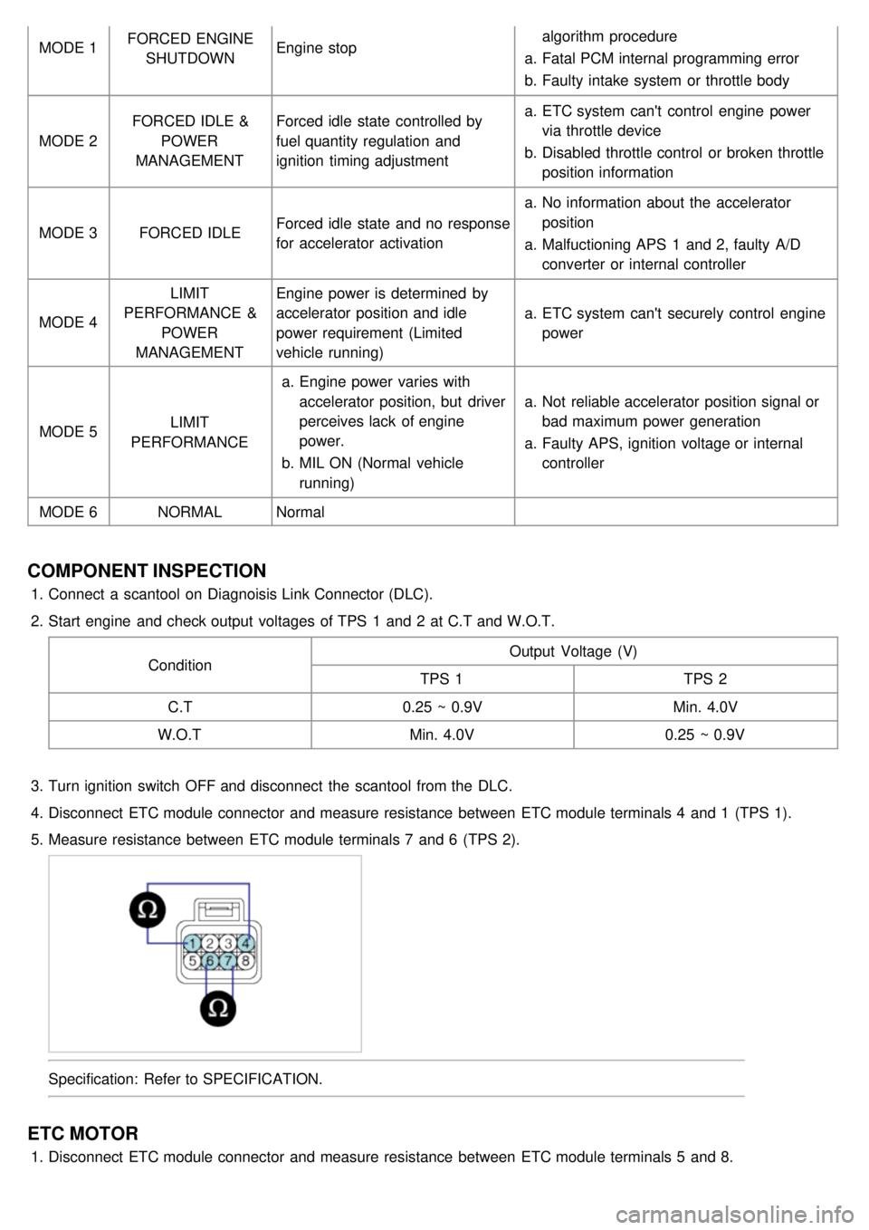
4. Disconnect ETC module connector and measure resistance between ETC module terminals 4 and 1 (TPS 1).
5. Measure resistance between ETC module terminals 7 and 6 (TPS 2).
Specification: Refer to SPECIFICATION.
ETC MOTOR
1.Disconnect ETC module connector and measure resistance between ETC module terminals 5 and 8.
Page 335 of 1575

A31N.A -- - -
A32 A/C Pressure Analog -- - --
A34 N.A -- - -
A36 N.A -- - -
A37 N.A -- - -
A41 CAN_HI Recessive
Dominant Pulse
2.0 ~ 3.0 V
2.75 ~ 4.5 V 3.85V
2.5V
A42 CAN_LO Recessive
Dominant Pulse
2.0 ~ 3.0 V
0.5 ~ 2.25 V 2.55V
1.34V
A60 A/T PWR Source IG Off
IG On
IG. Key On
IG. Key Off Idle
Key Off from Idle
Fuse 1/2/3
Removal Condition DC
Voltage Max. 0.5 V
V_BAT
MAX. +/ - 75V (ECU GND)
MAX. +/ - 75V (ECU GND)
MAX. +/ - 75V (ECU GND)
MAX. +/ - 75V (ECU GND)
MAX. +/ - 75V (ECU GND) 0V
11.9V
+30V / - 10V or less ↑
W/H Open DTC Spec : P0888DTC : P0888
A73 Shift Position
Signal(To Cluster) Running
1 gear
2 gear
3 gear
4 gear
5 gear Pulse
Duty ↑
↑
↑
↑ HI : V_BAT
LO : Max. 1.0V
Freq.: 50±2Hz (Reference) 12.5±2%
27.5±2%
42.5±2%
57.5±2%
72.5±2% N.A
Sports
mode
B03 UD Solenoid Shifting
Pulse HI : V_BAT
LO : Max. 1.0V
Vpeak : Max. 70V 14.4V
0.35V
56.3V
W/H Open DTC Spec : P0755DTC : P0755
B05 N.A -- - -
B06 Oil temperature
sensor_ATM Idle
Analog 0.5V ~ 4.5V 4.4V
3.1V16Hz
B09 Output speed sensor 30kph
Pulse HI : Min. 4.0V
LO : Max. 1.0V 5.08V
0.34V
W/H Open DTC Spec : P0722DTC : P0722
B10 Input speed sensor Idle
Pulse HI : Min. 4.0V
LO : Max. 1.0V 5.06V
0.35V
630Hz
W/H Open DTC Spec : P0717DTC : P0717
B20 N.A -- - -
B22 LR Solenoid Shifting
Pulse HI : V_BAT
LO : Max. 1.0V
Vpeak : Max. 70V 13.9V
0.38V
56.1V
W/H Open DTC Spec : P0750DTC : P0750
B26 N.A -- - -
B27 N.A -- - -
B33 GND_Sensor Idle
DC
Voltage Max. 50 mV
13mV
WTS &
OTS_ATM
W/H Open DTC Spec : P0118/ 1115DTC : P0118/
P1115
B42 OD Solenoid Shifting
Pulse HI : V_BAT
LO : Max. 1.0V
Vpeak : Max. 70V 15.4V
0.45V
56.3V
Page 353 of 1575

BRAKES
The gear changing mechanism utilizes two multi- disc brakes.
LOW&REVERSE BRAKE AND SECOND BRAKE
The low&reverse brake(A) operates in 1st and reverse gears, when the vehicle is parked, and during manual
operation. It locks the low&reverse annulus gear and overdrive planetary carrier to the case.
The second(C) brake(B) operates in 2nd and 4th gears and locks the reverse sun gear(D) to the case.
The components comprising the low&reverse brake and second brake are as illustrated below.
As shown, the discs and plates of the two brakes are arranged on either side of the rear cushion plate(E), which is
itself secured to the case(F) by a snap ring.
OWC
To improve the shift feeling from 1st to 2nd gear, OWC was adopted on the low&reverse brake annulus gear. Instead
of hydraulic fixing by Low&reverse brake at the 1st gear, this mechanical fixing device was used. This structure is not
a new concept, because this OWC already has been installed on the previous models.
ACCUMULATORS
NumberFunction Name Color
1 Low&Reverse Brake None
2 Underdrive Clutch Yellow
3 Second Brake Blue
4 Overdrive Clutch None
Page 354 of 1575
Objective
* Energy (hydraulic pressure) storage
* Impact and pulsation damping when solenoid valves operating
* Operation as spring element
* Smooth shifting by preventing sudden operation of clutches and brakes
TRANSFER DRIVE GEAR
With the transfer drive gear, increased tooth height and a higher contact ratio have reduced gear noise.
Also, the bearing that supports the drive gear is a preloaded type that eliminates rattle, and the rigidity of the gear
mounting has been increased by bolting the bearing directly onto the case.
OUTPUT SHAFT/TRANSFER DRIVEN GEAR
As shown in the illustration below, the transfer driven gear is press- fitted onto the output shaft, and the output shaft is
secured by a locking nut and supported by bearings.
The locking nut has a left- handed thread, and a hexagonal hole in the other end of the shaft enables the shaft to be
held in position for locking nut removal.