Page 60 of 1575
(4)Lightly tap the end of each valve stem two or three times with the wooden handle of a hammer to ensure
proper seating of the valve and retainer lock.
2. Install MLAs with engine oil applied on its surface.
Check that the MLA rotates smoothly by hand.
MLA should be reinstalled in its original position.
3. Install OCV(Oil Control Valve)(A).
Tightening torque
7.8 ~ 9.8Nm(0.8 ~ 1.0kgf.m, 5.8 ~ 7.2lb - ft)
a.To install OCV with gray colored connector into RH bank.
b. To install OCV with black colored connector into LH bank.
Page 71 of 1575
INSTALLATION
Installation is in the reverse order of removal.
Perform the following :a. Adjust the shift cable.
b. Refill the engine with engine oil.
c. Refill the transaxle with fluid.
d. Refill the radiator with engine coolant.
e. Bleed air from the cooling system with the heater valve open.
f. Clean the battery posts and cable terminals with sandpaper assemble them, then apply grease to prevent
corrosion.
g. Inspect for fuel leakage.
After assembling the fuel line, turn on the ignition switch (do not operate the starter) so that the fuel pump runs for
approximately two seconds and fuel line pressurizes.
Repeat this operation two or three times, then check for fuel leakage at any point in the fuel line.
Page 84 of 1575

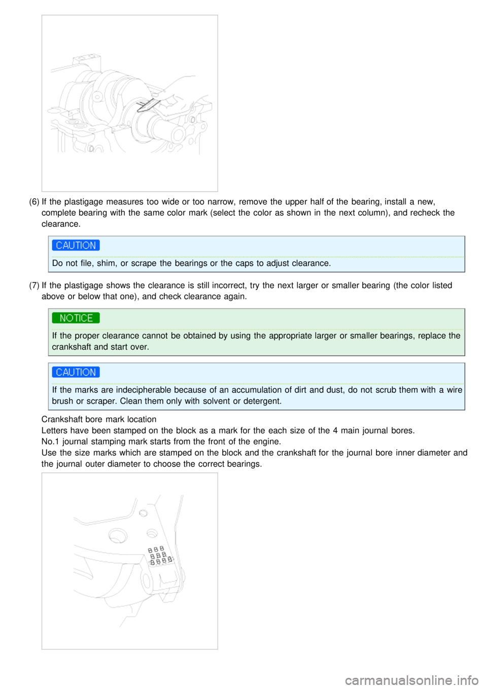
(6)If the plastigage measures too wide or too narrow, remove the upper half of the bearing, install a new,
complete bearing with the same color mark (select the color as shown in the next column), and recheck the
clearance.
Do not file, shim, or scrape the bearings or the caps to adjust clearance.
(7) If the plastigage shows the clearance is still incorrect, try the next larger or smaller bearing (the color listed
above or below that one), and check clearance again.
If the proper clearance cannot be obtained by using the appropriate larger or smaller bearings, replace the
crankshaft and start over.
If the marks are indecipherable because of an accumulation of dirt and dust, do not scrub them with a wire
brush or scraper. Clean them only with solvent or detergent.
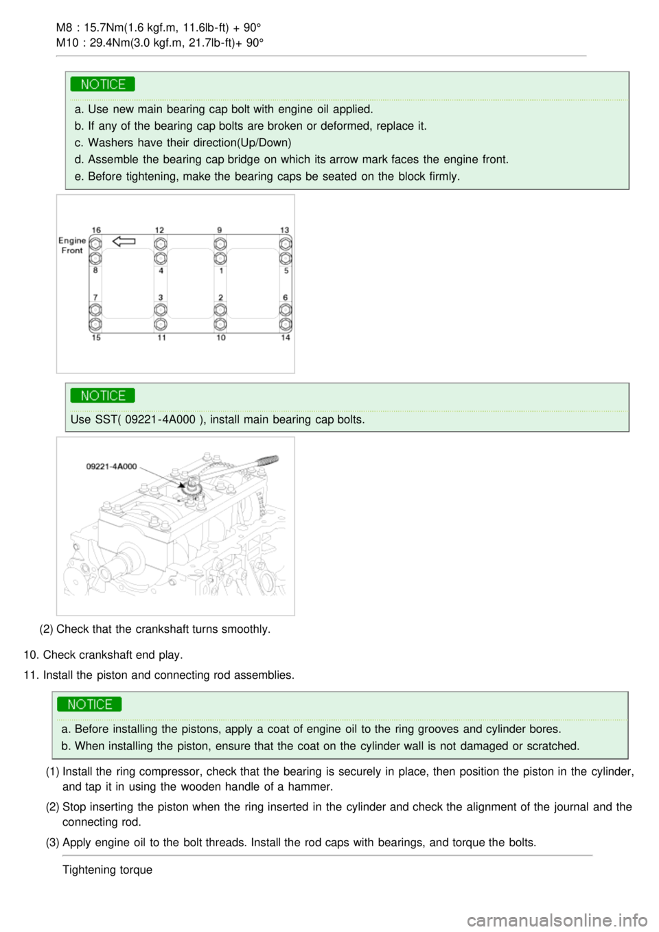
Crankshaft bore mark location
Letters have been stamped on the block as a mark for the each size of the 4 main journal bores.
No.1 journal stamping mark starts from the front of the engine.
Use the size marks which are stamped on the block and the crankshaft for the journal bore inner diameter and
the journal outer diameter to choose the correct bearings.
Page 95 of 1575

M8 : 15.7Nm(1.6 kgf.m, 11.6lb- ft) + 90°
M10 : 29.4Nm(3.0 kgf.m, 21.7lb- ft)+ 90°
a.Use new main bearing cap bolt with engine oil applied.
b. If any of the bearing cap bolts are broken or deformed, replace it.
c. Washers have their direction(Up/Down)
d. Assemble the bearing cap bridge on which its arrow mark faces the engine front.
e. Before tightening, make the bearing caps be seated on the block firmly.
Use SST( 09221 - 4A000 ), install main bearing cap bolts.
(2) Check that the crankshaft turns smoothly.
10. Check crankshaft end play.
11. Install the piston and connecting rod assemblies.
a.Before installing the pistons, apply a coat of engine oil to the ring grooves and cylinder bores.
b. When installing the piston, ensure that the coat on the cylinder wall is not damaged or scratched.
(1) Install the ring compressor, check that the bearing is securely in place, then position the piston in the cylinder,
and tap it in using the wooden handle of a hammer.
(2) Stop inserting the piston when the ring inserted in the cylinder and check the alignment of the journal and the
connecting rod.
(3) Apply engine oil to the bolt threads. Install the rod caps with bearings, and torque the bolts.
Tightening torque
Page 108 of 1575
Clean the contacting face before assembling.
2. Install the timing belt.
3. Install drive belt(A).
4.Fill with engine coolant.
5. Start engine and check for leaks.
6. Recheck engine coolant level.
WATER TEMPERATURE CONTROL ASSEMBLY
1.Install the water pipe(A).
Tightening torque
16.7 ~ 19.6Nm (1.7 ~ 2.0kgf.m, 12.3 ~ 14.5lb- ft)
2.Install the water temperature control assembly(A) with a new gasket(B).
Tightening torque
Page 109 of 1575
29.4 ~ 41.2Nm(3.0 ~ 4.2kgf.m, 21.7 ~ 30.4lb- ft
Use new O - rings and wet them with water or coolant when reassembling.
3. Install the wiring protector.
4. Connect the heater hose and ECT hose.
5. Connect the ECT sensor connector.
6. Connect the radiator upper and the lower hose(A).
7.Install the air cleaner assembly.
8. Fill with engine coolant.
9. Start engine and check for leaks.
10. Recheck engine coolant level.
THERMOSTAT
1.Place thermostat(B) in coolant inlet pitting(A).
Install the thermostat with the jiggle valve upward.
Page 110 of 1575
2.Install the coolant inlet pitting(A).
Tightening torque
16.66 ~ 19.60Nm (1.7 ~ 2.0kgf.m, 12.30 ~ 14.47lb- ft)
3. Fill with engine coolant.
4. Start engine and check for leaks.
RADIATOR
1.Install the radiator fan(A) to the radiator.
Tightening torque
4.9 ~ 7.8Nm (0.5 ~ 0.8kgf.m, 3.6 ~ 5.8lb - ft)
2. Install the radiator assembly to the vehicle.
3. Fix the condenser with the radiator assembly.
Tightening torque
4.9 ~ 7.8Nm (0.5 ~ 0.8kgf.m, 3.6 ~ 5.8lb - ft) - D
6.9 ~ 9.8Nm (0.7 ~ 1.0kgf.m, 5.1 ~ 7.2lb - ft) - C
4. Install the radiator bracket(A, B) and the bleeder hose(C).
LH
RH
Page 112 of 1575
7.Install the radiator upper(A) and lower hoses(B).
8.Install the radiator support upper member assembly(A).
9.Install the radiator grille upper cover(A).
10. Fill with engine coolant.
11. Start engine and check for leaks.
12. Recheck engine coolant level.
INSPECTION
WATER PUMP
1. Check each part for cracks, damage or wear, and replace the coolant pump assembly if necessary.
2. Check the bearing for damage, abnormal noise and sluggish rotation, and replace the coolant pump assembly if
necessary.
3. Check for coolant leakage. If coolant leaks from hole, the seal is defective. Replace the coolant pump assembly.
A small amount of "weeping" from the bleed hole is normal.