Page 299 of 1575

2007 > 2.7L V6 GASOLINE >
INSPECTION
FUNCTION AND OPERATION PRICIPLE
Based on information from various sensors, the PCM measures the fuel injection amount. The fuel injector is a
solenoid- operated valve and the fuel injection amount is controlled by length of time that the fuel injector is held open.
The PCM controls each injector by grounding the control circuit. When the PCM energizes the injector by grounding
the control circuit, the circuit voltage should be low (theoretically 0V) and the fuel is injected. When the PCM de-
energizes the injector by opening control circuit, the fuel injector is closed and circuit voltage should momentarily peak.
If an injector connector is disconnected for more than 46 seconds while the engine runs, the PCM will determine
that the cylinder is misfiring and cut fuel supply. So be careful not to exceed 46 seconds. But the engine runs
normally in 10 seconds after turning the ignition key off.
SPECIFICATION
Item Specification
Coil Resistance (Ω) 13.8 ~ 15.2Ω at 20°C (68°F)
CIRCUIT DIAGRAM
Page 303 of 1575

2007 > 2.7L V6 GASOLINE >
INSTALLATION
If the OCVs are installed incorrectly, the vehicle may be damaged.
So when installing them, ensure the OCV and harness connector colors match(Components and harness side).
[Bank and its color] Bank Component side Harness side
Bank 1 (RH) GreyGrey
Bank 2 (LH) BlackBlack
INSPECTION
FUNCTION AND OPERATION PRICIPLE
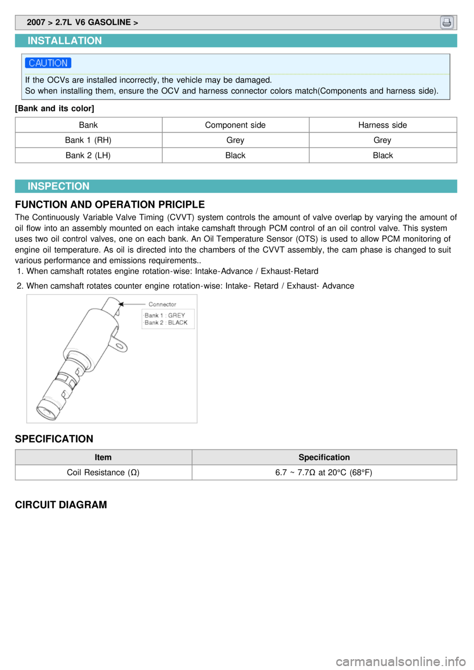
The Continuously Variable Valve Timing (CVVT) system controls the amount of valve overlap by varying the amount of
oil flow into an assembly mounted on each intake camshaft through PCM control of an oil control valve. This system
uses two oil control valves, one on each bank. An Oil Temperature Sensor (OTS) is used to allow PCM monitoring of
engine oil temperature. As oil is directed into the chambers of the CVVT assembly, the cam phase is changed to suit
various performance and emissions requirements.. 1. When camshaft rotates engine rotation- wise: Intake- Advance / Exhaust- Retard
2. When camshaft rotates counter engine rotation- wise: Intake- Retard / Exhaust- Advance
SPECIFICATION
Item Specification
Coil Resistance (Ω) 6.7 ~ 7.7Ω at 20°C (68°F)
CIRCUIT DIAGRAM
Page 306 of 1575
2007 > 2.7L V6 GASOLINE >
INSPECTION
FUNCTION AND OPERATION PRICIPLE
Variable Intake manifold Solenoid (VIS) valves are installed on surge tank (VIS Valve #1) and intake manifold (VIS
Valve #2). These VIS valve #1 and #2 control vacuum modulators which activate valves in surge tank and intake
manifold. These valves are opened or closed by PCM according to engine condition (Refer to below table).
Engine Condition VIS Valve #1
(Surge Tank) VIS Valve #2
(In - manifold) Operation
Low
Speed Closed
ClosedIncreasing engine performance in low engine speed by
reducing intake interference among cylinders
Medium Speed Open
Open or closed Increasing intake efficiency
High
Speed Open
OpenMinimizing intake resistance by shortening intake manifold
length and increasing area of air entrance
SPECIFICATION
Item
Specification
Coil Resistance (Ω) 29.0 ~ 35.0 Ω at 20°C (68°F)
CIRCUIT DIAGRAM
Page 312 of 1575

MODE 1FORCED ENGINE
SHUTDOWN Engine stop algorithm procedure
a. Fatal PCM internal programming error
b. Faulty intake system or throttle body
MODE 2 FORCED IDLE &
POWER
MANAGEMENT Forced idle state controlled by
fuel quantity regulation and
ignition timing adjustment a.
ETC system can't control engine power
via throttle device
b. Disabled throttle control or broken throttle
position information
MODE 3 FORCED IDLE Forced idle state and no response
for accelerator activation a.
No information about the accelerator
position
a. Malfuctioning APS 1 and 2, faulty A/D
converter or internal controller
MODE 4 LIMIT
PERFORMANCE & POWER
MANAGEMENT Engine power is determined by
accelerator position and idle
power requirement (Limited
vehicle running)
a.
ETC system can't securely control engine
power
MODE 5 LIMIT
PERFORMANCE a.
Engine power varies with
accelerator position, but driver
perceives lack of engine
power.
b. MIL ON (Normal vehicle
running) a.
Not reliable accelerator position signal or
bad maximum power generation
a. Faulty APS, ignition voltage or internal
controller
MODE 6 NORMALNormal
COMPONENT INSPECTION
1.Connect a scantool on Diagnoisis Link Connector (DLC).
2. Start engine and check output voltages of TPS 1 and 2 at C.T and W.O.T.
Condition Output Voltage (V)
TPS 1 TPS 2
C.T 0.25 ~ 0.9V Min. 4.0V
W.O.T Min. 4.0V 0.25 ~ 0.9V
3. Turn ignition switch OFF and disconnect the scantool from the DLC.
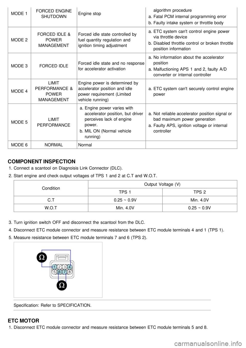
4. Disconnect ETC module connector and measure resistance between ETC module terminals 4 and 1 (TPS 1).
5. Measure resistance between ETC module terminals 7 and 6 (TPS 2).
Specification: Refer to SPECIFICATION.
ETC MOTOR
1.Disconnect ETC module connector and measure resistance between ETC module terminals 5 and 8.
Page 320 of 1575
2007 > 2.7L V6 GASOLINE >
REMOVAL
1.Preparation
(1) Remove the 2nd seat(s) (Refer to "BD" group in this WORKSHOP MANUAL).
(2) Remove the striker cover (A).
(3) Remove the Service Cover (B).
(4)Disconnect the Fuel Pump Connector (A).
(5)Start the engine and wait until fuel in fuel line is exhausted.
(6) After the engine stalls, turn the ignition switch OFF.
2. Lift the vehicle and support it with a jack.
Page 323 of 1575
2007 > 2.7L V6 GASOLINE >
REMOVAL(INCLUDING FUEL FILTER AND FUEL PRESSURE REGULATOR)
1.Preparation
(1) Remove the 2nd seat(s) (Refer to "BD" group in this WORKSHOP MANUAL).
(2) Remove the striker cover (A).
(3) Remove the Service Cover (B).
(4)Disconnect the Fuel Pump Connector (A).
(5)Start the engine and wait until fuel in fuel line is exhausted.
(6) After the engine stalls, turn the ignition switch OFF.
2. After disconnecting the fuel feed quick connector (A) and unscrewing the the eight screws (B), remove the fuel
pump assembly.
Page 327 of 1575
2007 > 2.7L V6 GASOLINE >
SPECIAL TOOLS
TOOL
(Number and name) Illustration
Use
09200 - 38001
Engine support fixture
Removal and installation of transaxle.
Page 328 of 1575

2007 > 2.7L V6 GASOLINE >
SPECIFICATION
Item F4A51
Torque converter type 3 - element, 1 - stage, 2 - phase type
Transaxle type 4 - speed forward, 1 - speed reverse
Engine displacement 2.7L GSL
Gear ratio 1st
2.842
2nd 1.495
3rd 1.000
4th 0.731
Reverse 2.720
Final gear ratio 4.520
Shift pattern Variable
Shift range 4range ( P- R- N- D) + Sports mode
Shift range valve PWM ; 5EA(Duty control) , VFS
Planetary gear 2EA(Output planetary/Overdrive planetary)
Clutch 3EA
Brake 2EA
OWC 1EA
TIGHTENING TORQUE ITEM Nmkgf·m lb- ft
Control cable nut 8 ~ 120.8 ~ 1.2 5.8 ~ 8.6
Input shaft speed sensor 10 ~ 121.0 ~1.2 7 ~ 8
Output shaft speed sensor 10 ~ 121.0 ~1.2 7 ~ 8
Manual control lever 18 ~ 251.8 ~ 2.5 13 ~ 18
Transaxle range switch 10 ~ 121.0 ~1.2 7 ~ 8
Valve body cover 10 ~ 121.0 ~1.2 7 ~ 8
Valve body mounting bolt 10 ~ 121.0 ~1.2 7 ~ 8
Oil temperature sensor 10 ~ 121.0 ~1.2 7 ~ 8
Oil filler plug 29 ~ 342.9 ~ 3.421.4 ~ 25.1
Oil drain plug 40 ~ 504.0 ~ 5.0 29 ~ 36
Solenoid valve support 5 ~ 70.5 ~ 0.7 4 ~ 5
Pressure check plug 8 ~ 100.8 ~ 1.0 6 ~ 7
Transaxle mounting sub bracket nut 60 ~ 806.0 ~ 8.0 43 ~ 58
Transaxle mounting bracket bolts 40 ~ 554.0 ~ 5.5 29 ~ 40
Transaxle mounting insulator bolt 90 ~ 1109.0 ~ 1165 ~ 80
Transaxle and engine mounting bolt 65 ~ 856.5 ~ 8.5 47 ~ 61.5
Drive plate bolt 46 ~ 534.6 ~ 5.333.3 ~ 38.3