2007 KIA CARNIVAL ECU
[x] Cancel search: ECUPage 1156 of 1575

3.Isolate the problem by testing the circuit
Make circuit tests to check the diagnosis you made in step 2. Keep in mind that a logical, simple procedure is the
key to efficient troubleshooting.
Test for the most likely cause of failure first. Try to make tests at points that are easily accessible.
4. Fix the problem
Once the specific problem is identified, make the repair. Be sure to use proper tools and safe procedures.
5. Make sure the circuit works
Turn on all components in the repaired circuit in all modes to make sure you've fixed the entire problem. If the
problem was a blown fuse, be sure to test all of the circuits on the fuse. Make sure no new problems turn up and
the original problem does not recur
Page 1230 of 1575
g.7th : Light ON warning
h. 8th : Key learning sound
3. If two different warning condition happen at the same time, chime should work only for the highest warning
condition.
4. Cluster indicators should work for two warning behavior.
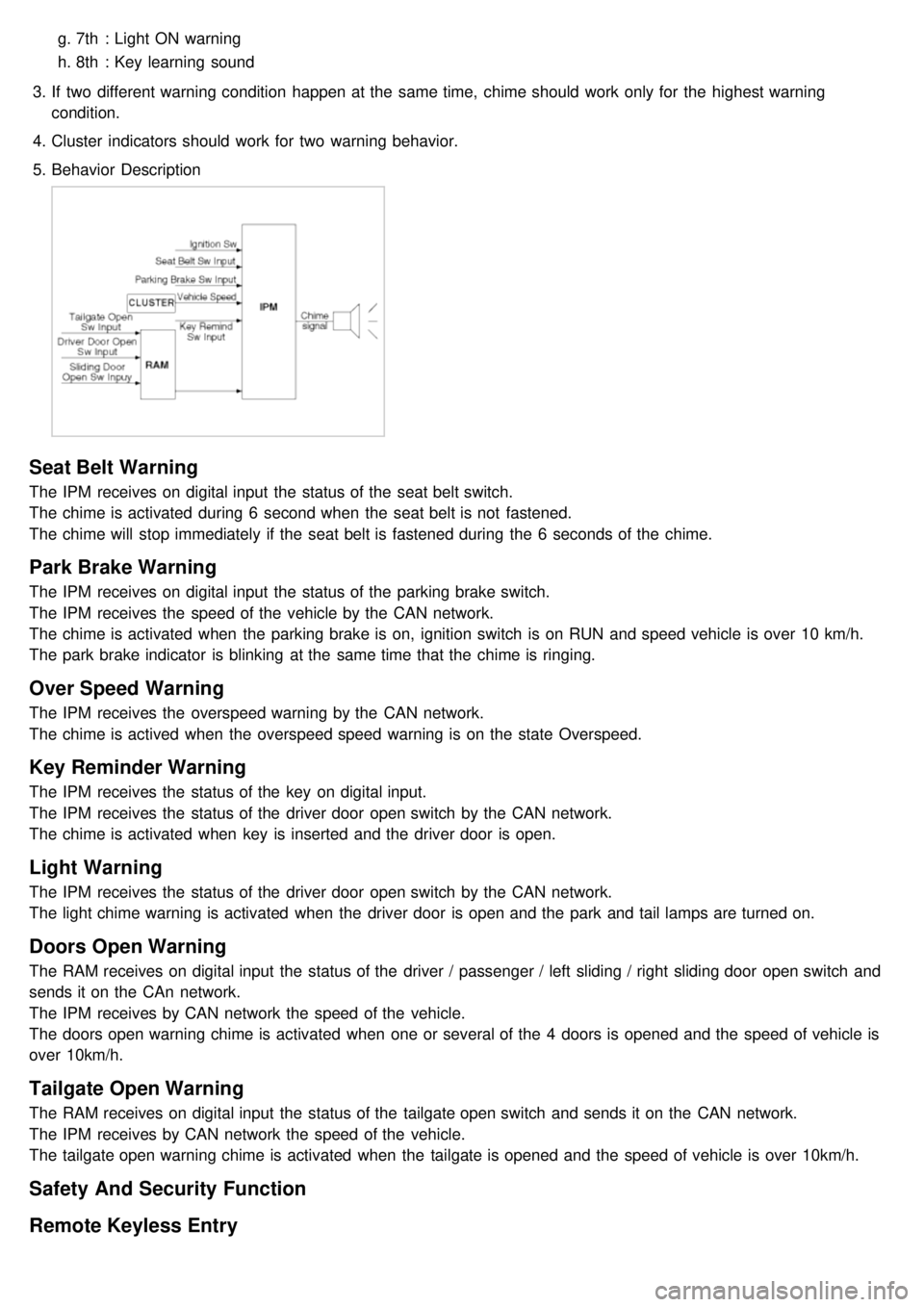
5. Behavior Description
Seat Belt Warning
The IPM receives on digital input the status of the seat belt switch.
The chime is activated during 6 second when the seat belt is not fastened.
The chime will stop immediately if the seat belt is fastened during the 6 seconds of the chime.
Park Brake Warning
The IPM receives on digital input the status of the parking brake switch.
The IPM receives the speed of the vehicle by the CAN network.
The chime is activated when the parking brake is on, ignition switch is on RUN and speed vehicle is over 10 km/h.
The park brake indicator is blinking at the same time that the chime is ringing.
Over Speed Warning
The IPM receives the overspeed warning by the CAN network.
The chime is actived when the overspeed speed warning is on the state Overspeed.
Key Reminder Warning
The IPM receives the status of the key on digital input.
The IPM receives the status of the driver door open switch by the CAN network.
The chime is activated when key is inserted and the driver door is open.
Light Warning
The IPM receives the status of the driver door open switch by the CAN network.
The light chime warning is activated when the driver door is open and the park and tail lamps are turned on.
Doors Open Warning
The RAM receives on digital input the status of the driver / passenger / left sliding / right sliding door open switch and
sends it on the CAn network.
The IPM receives by CAN network the speed of the vehicle.
The doors open warning chime is activated when one or several of the 4 doors is opened and the speed of vehicle is
over 10km/h.
Tailgate Open Warning
The RAM receives on digital input the status of the tailgate open switch and sends it on the CAN network.
The IPM receives by CAN network the speed of the vehicle.
The tailgate open warning chime is activated when the tailgate is opened and the speed of vehicle is over 10km/h.
Safety And Security Function
Remote Keyless Entry
Page 1236 of 1575
Battery Removal
a.If the battery is removed with the system in the ARM state, the system will be placed into the ARM state upon
battery reconnect.
b. The ALARM state will be re- activated if the battery is disconnected, then reconnected, with the system in an
ALARM state.
c. If the battery is disconnected and reconnected with the system in AFTER ALARM state, the alarm will be re-
activated.
d. The system will enter DISARM mode if the battery is disconnected during the ALARM WAIT state.
Panic
a.If RKE PANIC signal is received, Siren output and hazard lamp operate for 27 seconds and the system return to
the previous state as soon as the PANIC function finishes.
b. The PANIC function will be stopped if any RKE signal is received during PANIC activation..
c. If Key reminder switch is ON during PANIC function is operating, PANIC is stopped immediately.
d. If the system goes to ALARM mode during PANIC function is operating, PANIC is stopped immediately and then
ALARM function should be activated.
e. During ALARM state;
If RKE PANIC signal is received, ALARM mode is maintained and PANIC function should be ignored. ALARM has
higher priority than PANIC function.
f. During AFTER_ALARM state;
If RKE PANIC signal is received, AFTR_ALARM mode is maintained and PANIC function should be activated.
Safe & Rescue Mode
The goal of those modes is to be able to cope with failures that may happen on some of the most critical
functionalities (for the driver security) of the system.
Safe Mode
The safe mode is entered in case of system problems such as:
a. Incoherent inputs on monitored signals. In this case, safe mode is the debouncing time before the inputs are
considered INVALID. Note that today, we have no way to detect if the rain/light sensor is in working operation or
not. It means that a driver action will be required in case of failure of this sensor;
b. Loss of the CAN frame containing the monitored signal:
c. Loss of the CAN network: CAN goes to BUS OFF state, safe mode is the time necessary for detecting the BUS
OFF state.
In all cases, the action in safe mode is to maintain the previous state of the system (for lighting and wiping). The list of
monitored signals is the same as in rescue mode
Exiting Safe Mode
The software safe mode is exited and the module goes back to the normal mode when: a. On IPM, hardware inputs return to a coherent state;
b. The lost CAN signal comes back while timeout has not elapsed;
c. The CAN network returns to a normal state without reaching BUS OFF state.
Software safe mode is also exited when the software rescue mode is entered (problem does not disappear).
Hardware safe mode is exited and the module goes back to normal mode if the internal problem disappears (watchdog
is properly triggered again). If the problem stays, hardware safe mode is exited to enter hardware rescue mode.
Rescue Modes
The rescue mode consists in activating some safety functions when IGN2 = ON: a. Switch on the low beams (FAM), park lamps (FAM), tail lamps (RAM) and cluster backlighting (IPM);
b. Unlock of all the doors when the rescue mode is entered with IGN2 = ON
c. Front wipers do not need to be turned on by software in rescue mode because wipers can be turned on by
manually setting the MF switch to low speed. The FAM software must keep the same state as before entering the
rescue mode.
d. When IGN2 = OFF, low beams, park/tail lamps and cluster backlighting are turned off.
Entering Rescue Modes
Page 1239 of 1575
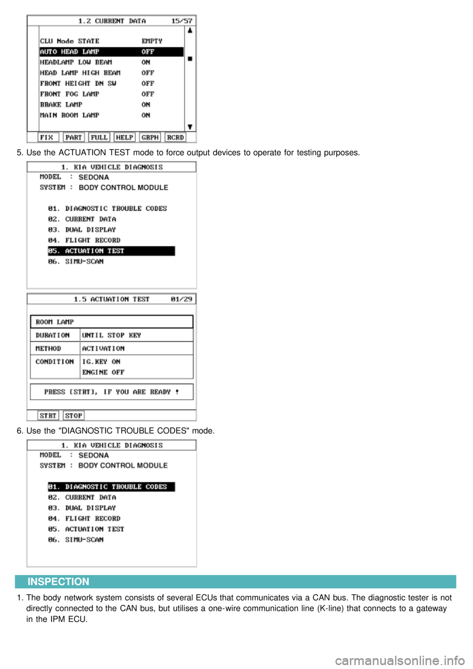
5.Use the ACTUATION TEST mode to force output devices to operate for testing purposes.
6.Use the "DIAGNOSTIC TROUBLE CODES" mode.
INSPECTION
1.The body network system consists of several ECUs that communicates via a CAN bus. The diagnostic tester is not
directly connected to the CAN bus, but utilises a one- wire communication line (K- line) that connects to a gateway
in the IPM ECU.
Page 1262 of 1575
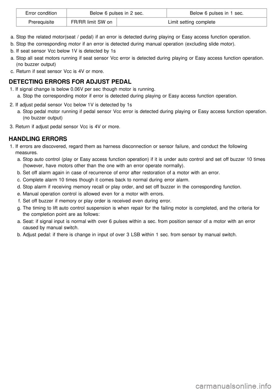
Error conditionBelow 6 pulses in 2 sec. Below 6 pulses in 1 sec.
Prerequisite FR/RR limit SW on Limit setting complete
a. Stop the related motor(seat / pedal) if an error is detected during playing or Easy access function operation.
b. Stop the corresponding motor if an error is detected during manual operation (excluding slide motor).
b. If seat sensor Vcc below 1V is detected by 1s
a. Stop all seat motors running if seat sensor Vcc error is detected during playing or Easy access function operation.
(no buzzer output)
c. Return if seat sensor Vcc is 4V or more.
DETECTING ERRORS FOR ADJUST PEDAL
1.If signal change is below 0.06V per sec though motor is running.
a. Stop the corresponding motor if error is detected during playing or Easy access function operation.
2. If adjust pedal sensor Vcc below 1V is detected by 1s
a. Stop pedal motor running if pedal sensor Vcc error is detected during playing or Easy access function operation.
(no buzzer output)
3. Return if adjust pedal sensor Vcc is 4V or more.
HANDLING ERRORS
1.If errors are discovered, regard them as harness disconnection or sensor failure, and conduct the following
measures.
a. Stop auto control (play or Easy access function operation) if it is under auto control and set off buzzer 10 times
(however, have motors other than the one with an error operate normally).
b. Set off alarm again in case of recurrence of error after restoration of a motor with an error.
c. Complete alarm 10 times though it comes back to normal during error alarm.
d. Stop alarm if receiving memory recall or play order, and set off buzzer in the corresponding function.
e. Manual operation control is allowed even for a motor with errors.
f. Set off buzzer if memory or play order is received even during error.
g. The timing to lift auto control suspension is when repair for the failing motor is completed, and the criteria for
the completion point are as follows:
a. Seat: if signal input is normal with over 6 pulses within a sec. from position sensor of a motor with an error
caused by manual switch.
b. Adjust pedal: if there is change in input of over 3 LSB within 1 sec. from sensor by manual switch.
Page 1290 of 1575
2007 > 2.7L V6 GASOLINE >
INSPECTION
FUSE
1. Be sure there is no play in the fuse holders, and that the fuses are held securely.
2. Are the fuse capacities for each circuit correct?
3. Are there any blown fuses ?
If a fuse is to be replaced, be sure to use a new fuse of the same capacity. Always determine why the fuse blew
first and completely eliminate the problem before installing a new fuse.
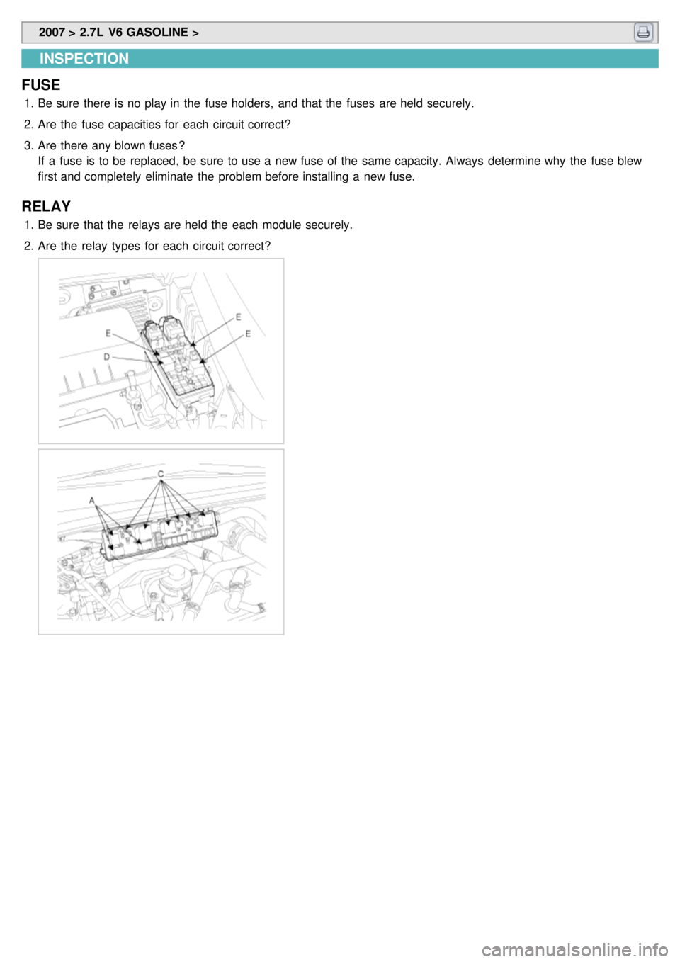
RELAY
1.Be sure that the relays are held the each module securely.
2. Are the relay types for each circuit correct?
Page 1298 of 1575
2007 > 2.7L V6 GASOLINE >
INSPECTION
FUSE
1. Be sure there is no play in the fuse holders, and that the fuses are held securely.
2. Are the fuse capacities for each circuit correct?
3. Are there any blown fuses ?
If a fuse is to be replaced, be sure to use a new fuse of the same capacity. Always determine why the fuse blew
first and completely eliminate the problem before installing a new fuse.
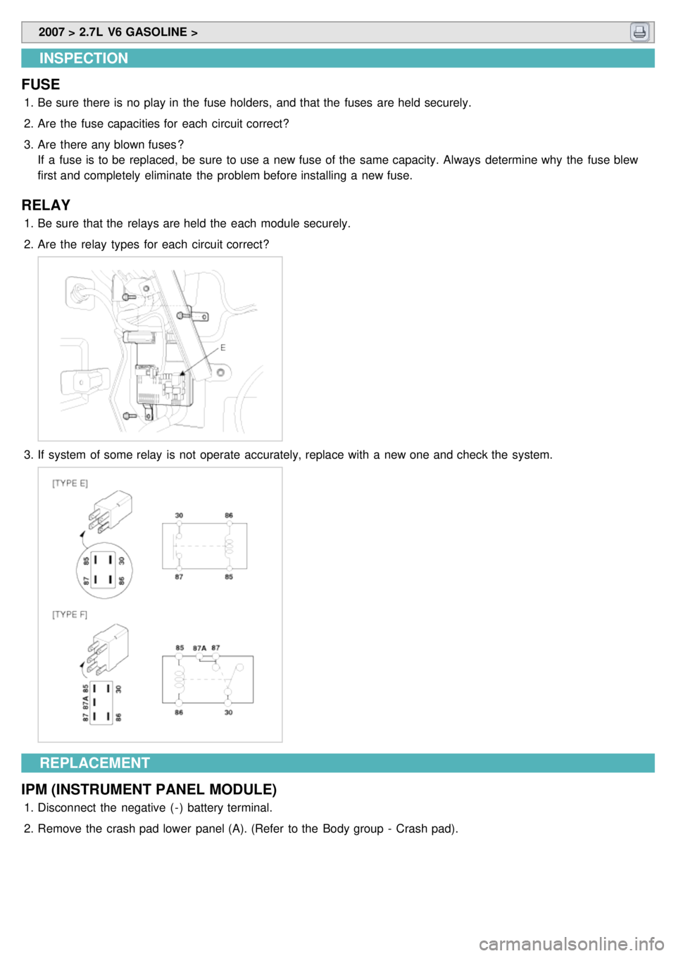
RELAY
1.Be sure that the relays are held the each module securely.
2. Are the relay types for each circuit correct?
3.If system of some relay is not operate accurately, replace with a new one and check the system.
REPLACEMENT
IPM (INSTRUMENT PANEL MODULE)
1. Disconnect the negative ( - ) battery terminal.
2. Remove the crash pad lower panel (A). (Refer to the Body group - Crash pad).
Page 1334 of 1575
Bound cablesReplace drive unit if necessary
Binding or sticking of components Establish location of binding and replace
necessary components
Grade of vehicle too steep for power
operation Operate sliding door manually
Failure of sliding door motor assembly Replace motor assembly, if necessary
Squeaks, Noises and rattles Foreign material in Sliding Door Remove foreign material
Worn or Loose components Check and tighten loose components
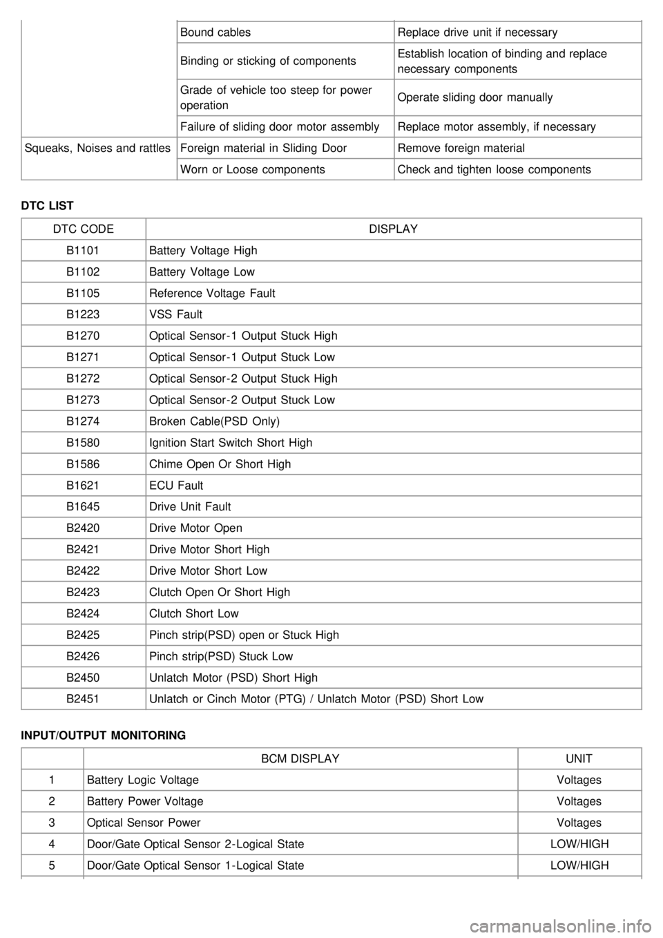
DTC LIST DTC CODE DISPLAY
B1101 Battery Voltage High
B1102 Battery Voltage Low
B1105 Reference Voltage Fault
B1223 VSS Fault
B1270 Optical Sensor - 1 Output Stuck High
B1271 Optical Sensor - 1 Output Stuck Low
B1272 Optical Sensor - 2 Output Stuck High
B1273 Optical Sensor - 2 Output Stuck Low
B1274 Broken Cable(PSD Only)
B1580 Ignition Start Switch Short High
B1586 Chime Open Or Short High
B1621 ECU Fault
B1645 Drive Unit Fault
B2420 Drive Motor Open
B2421 Drive Motor Short High
B2422 Drive Motor Short Low
B2423 Clutch Open Or Short High
B2424 Clutch Short Low
B2425 Pinch strip(PSD) open or Stuck High
B2426 Pinch strip(PSD) Stuck Low
B2450 Unlatch Motor (PSD) Short High
B2451 Unlatch or Cinch Motor (PTG) / Unlatch Motor (PSD) Short Low
INPUT/OUTPUT MONITORING BCM DISPLAY UNIT
1 Battery Logic Voltage Voltages
2 Battery Power Voltage Voltages
3 Optical Sensor Power Voltages
4 Door/Gate Optical Sensor 2 - Logical State LOW/HIGH
5 Door/Gate Optical Sensor 1 - Logical State LOW/HIGH