2007 ISUZU KB P190 Circuit
[x] Cancel search: CircuitPage 3397 of 6020
Engine Management – V6 – Diagnostics Page 6C1-2–119
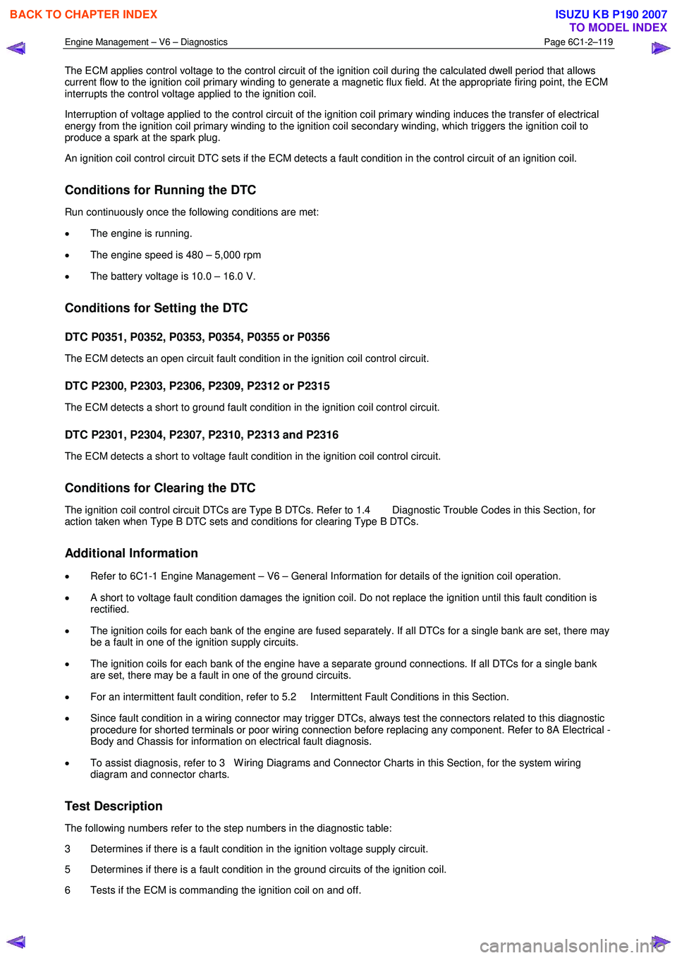
The ECM applies control voltage to the control circuit of the ignition coil during the calculated dwell period that allows
current flow to the ignition coil primary winding to generate a magnetic flux field. At the appropriate firing point, the ECM
interrupts the control voltage applied to the ignition coil.
Interruption of voltage applied to the control circuit of the ignition coil primary winding induces the transfer of electrical
energy from the ignition coil primary winding to the ignition coil secondary winding, which triggers the ignition coil to
produce a spark at the spark plug.
An ignition coil control circuit DTC sets if the ECM detects a fault condition in the control circuit of an ignition coil.
Conditions for Running the DTC
Run continuously once the following conditions are met:
• The engine is running.
• The engine speed is 480 – 5,000 rpm
• The battery voltage is 10.0 – 16.0 V.
Conditions for Setting the DTC
DTC P0351, P0352, P0353, P0354, P0355 or P0356
The ECM detects an open circuit fault condition in the ignition coil control circuit.
DTC P2300, P2303, P2306, P2309, P2312 or P2315
The ECM detects a short to ground fault condition in the ignition coil control circuit.
DTC P2301, P2304, P2307, P2310, P2313 and P2316
The ECM detects a short to voltage fault condition in the ignition coil control circuit.
Conditions for Clearing the DTC
The ignition coil control circuit DTCs are Type B DTCs. Refer to 1.4 Diagnostic Trouble Codes in this Section, for
action taken when Type B DTC sets and conditions for clearing Type B DTCs.
Additional Information
• Refer to 6C1-1 Engine Management – V6 – General Information for details of the ignition coil operation.
• A short to voltage fault condition damages the ignition coil. Do not replace the ignition until this fault condition is
rectified.
• The ignition coils for each bank of the engine are fused separately. If all DTCs for a single bank are set, there may
be a fault in one of the ignition supply circuits.
• The ignition coils for each bank of the engine have a separate ground connections. If all DTCs for a single bank
are set, there may be a fault in one of the ground circuits.
• For an intermittent fault condition, refer to 5.2 Intermittent Fault Conditions in this Section.
• Since fault condition in a wiring connector may trigger DTCs, always test the connectors related to this diagnostic
procedure for shorted terminals or poor wiring connection before replacing any component. Refer to 8A Electrical -
Body and Chassis for information on electrical fault diagnosis.
• To assist diagnosis, refer to 3 W iring Diagrams and Connector Charts in this Section, for the system wiring
diagram and connector charts.
Test Description
The following numbers refer to the step numbers in the diagnostic table:
3 Determines if there is a fault condition in the ignition voltage supply circuit.
5 Determines if there is a fault condition in the ground circuits of the ignition coil.
6 Tests if the ECM is commanding the ignition coil on and off.
BACK TO CHAPTER INDEX
TO MODEL INDEX
ISUZU KB P190 2007
Page 3398 of 6020
Engine Management – V6 – Diagnostics Page 6C1-2–120
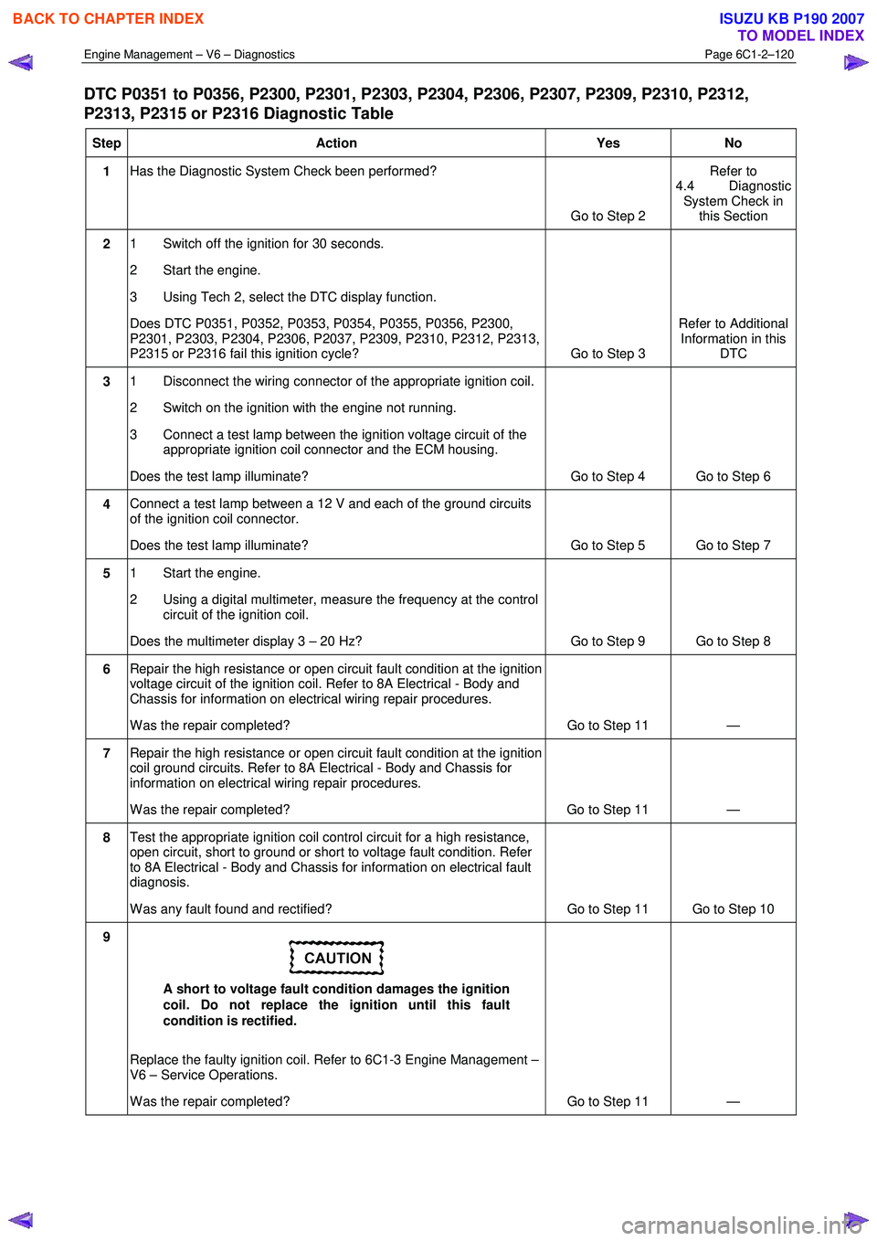
DTC P0351 to P0356, P2300, P2301, P2303, P2304, P2306, P2307, P2309, P2310, P2312,
P2313, P2315 or P2316 Diagnostic Table
Step Action Yes No
1 Has the Diagnostic System Check been performed?
Go to Step 2 Refer to
4.4 Diagnostic System Check in this Section
2 1 Switch off the ignition for 30 seconds.
2 Start the engine.
3 Using Tech 2, select the DTC display function.
Does DTC P0351, P0352, P0353, P0354, P0355, P0356, P2300,
P2301, P2303, P2304, P2306, P2037, P2309, P2310, P2312, P2313,
P2315 or P2316 fail this ignition cycle? Go to Step 3 Refer to Additional
Information in this DTC
3 1 Disconnect the wiring connector of the appropriate ignition coil.
2 Switch on the ignition with the engine not running.
3 Connect a test lamp between the ignition voltage circuit of the appropriate ignition coil connector and the ECM housing.
Does the test lamp illuminate? Go to Step 4 Go to Step 6
4 Connect a test lamp between a 12 V and each of the ground circuits
of the ignition coil connector.
Does the test lamp illuminate? Go to Step 5 Go to Step 7
5 1 Start the engine.
2 Using a digital multimeter, measure the frequency at the control circuit of the ignition coil.
Does the multimeter display 3 – 20 Hz? Go to Step 9 Go to Step 8
6 Repair the high resistance or open circuit fault condition at the ignition
voltage circuit of the ignition coil. Refer to 8A Electrical - Body and
Chassis for information on electrical wiring repair procedures.
W as the repair completed? Go to Step 11 —
7 Repair the high resistance or open circuit fault condition at the ignition
coil ground circuits. Refer to 8A Electrical - Body and Chassis for
information on electrical wiring repair procedures.
W as the repair completed? Go to Step 11 —
8 Test the appropriate ignition coil control circuit for a high resistance,
open circuit, short to ground or short to voltage fault condition. Refer
to 8A Electrical - Body and Chassis for information on electrical fault
diagnosis.
W as any fault found and rectified? Go to Step 11 Go to Step 10
9
A short to voltage fault condition damages the ignition
coil. Do not replace the ignition until this fault
condition is rectified.
Replace the faulty ignition coil. Refer to 6C1-3 Engine Management –
V6 – Service Operations.
W as the repair completed? Go to Step 11 —
BACK TO CHAPTER INDEX
TO MODEL INDEX
ISUZU KB P190 2007
Page 3399 of 6020
Engine Management – V6 – Diagnostics Page 6C1-2–121
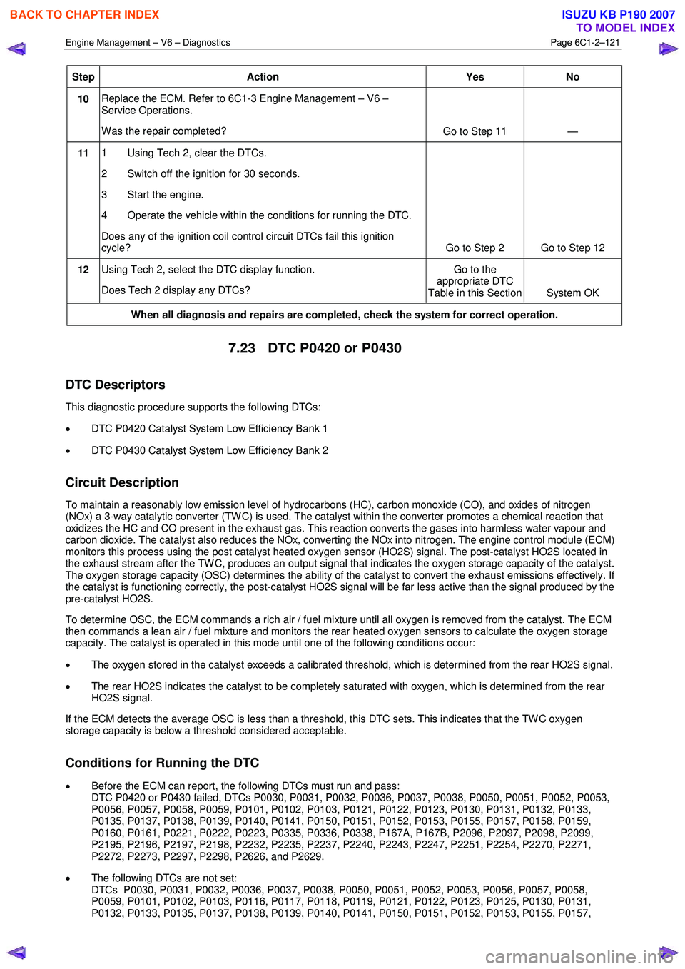
Step Action Yes No
10 Replace the ECM. Refer to 6C1-3 Engine Management – V6 –
Service Operations.
W as the repair completed? Go to Step 11 —
11 1 Using Tech 2, clear the DTCs.
2 Switch off the ignition for 30 seconds.
3 Start the engine.
4 Operate the vehicle within the conditions for running the DTC.
Does any of the ignition coil control circuit DTCs fail this ignition
cycle? Go to Step 2 Go to Step 12
12 Using Tech 2, select the DTC display function.
Does Tech 2 display any DTCs? Go to the
appropriate DTC
Table in this Section System OK
When all diagnosis and repairs are completed, check the system for correct operation.
7.23 DTC P0420 or P0430
DTC Descriptors
This diagnostic procedure supports the following DTCs:
• DTC P0420 Catalyst System Low Efficiency Bank 1
• DTC P0430 Catalyst System Low Efficiency Bank 2
Circuit Description
To maintain a reasonably low emission level of hydrocarbons (HC), carbon monoxide (CO), and oxides of nitrogen
(NOx) a 3-way catalytic converter (TW C) is used. The catalyst within the converter promotes a chemical reaction that
oxidizes the HC and CO present in the exhaust gas. This reaction converts the gases into harmless water vapour and
carbon dioxide. The catalyst also reduces the NOx, converting the NOx into nitrogen. The engine control module (ECM)
monitors this process using the post catalyst heated oxygen sensor (HO2S) signal. The post-catalyst HO2S located in
the exhaust stream after the TW C, produces an output signal that indicates the oxygen storage capacity of the catalyst.
The oxygen storage capacity (OSC) determines the ability of the catalyst to convert the exhaust emissions effectively. If
the catalyst is functioning correctly, the post-catalyst HO2S signal will be far less active than the signal produced by the
pre-catalyst HO2S.
To determine OSC, the ECM commands a rich air / fuel mixture until all oxygen is removed from the catalyst. The ECM
then commands a lean air / fuel mixture and monitors the rear heated oxygen sensors to calculate the oxygen storage
capacity. The catalyst is operated in this mode until one of the following conditions occur:
• The oxygen stored in the catalyst exceeds a calibrated threshold, which is determined from the rear HO2S signal.
• The rear HO2S indicates the catalyst to be completely saturated with oxygen, which is determined from the rear
HO2S signal.
If the ECM detects the average OSC is less than a threshold, this DTC sets. This indicates that the TW C oxygen
storage capacity is below a threshold considered acceptable.
Conditions for Running the DTC
• Before the ECM can report, the following DTCs must run and pass:
DTC P0420 or P0430 failed, DTCs P0030, P0031, P0032, P0036, P0037, P0038, P0050, P0051, P0052, P0053,
P0056, P0057, P0058, P0059, P0101, P0102, P0103, P0121, P0122, P0123, P0130, P0131, P0132, P0133,
P0135, P0137, P0138, P0139, P0140, P0141, P0150, P0151, P0152, P0153, P0155, P0157, P0158, P0159,
P0160, P0161, P0221, P0222, P0223, P0335, P0336, P0338, P167A, P167B, P2096, P2097, P2098, P2099,
P2195, P2196, P2197, P2198, P2232, P2235, P2237, P2240, P2243, P2247, P2251, P2254, P2270, P2271,
P2272, P2273, P2297, P2298, P2626, and P2629.
• The following DTCs are not set:
DTCs P0030, P0031, P0032, P0036, P0037, P0038, P0050, P0051, P0052, P0053, P0056, P0057, P0058,
P0059, P0101, P0102, P0103, P0116, P0117, P0118, P0119, P0121, P0122, P0123, P0125, P0130, P0131,
P0132, P0133, P0135, P0137, P0138, P0139, P0140, P0141, P0150, P0151, P0152, P0153, P0155, P0157,
BACK TO CHAPTER INDEX
TO MODEL INDEX
ISUZU KB P190 2007
Page 3400 of 6020
Engine Management – V6 – Diagnostics Page 6C1-2–122
P0158, P0159, P0160, P0161, P0221, P0222, P0223, P0300, P0301-P0306, P0443, P0458, P0459, P0496,
P167A, P167B, P2096, P2097, P2098, P2099, P2100, P2101, P2107, P2119, P2122, P2123, P2127, P2128,
P2138, P2176, P2177, P2178, P2179, P2180, P2187, P2188, P2189, P2190, P2195, P2196, P2197, P2198,
P2232, P2235, P2237, P2240, P2243, P2247, P2251, P2254, P2270, P2271, P2272, P2273, P2297, P2298,
P2626, and P2629.
• The engine speed is 1,040 – 3,000 rpm.
• The air flow into the engine is between 7.0 – 16.0 g/s and not changing more than 3.0 g/s
• The engine intake air temperature (IAT) at engine start-up is more than –30° C.
• The engine is operating for more than 7 minutes.
• The engine is operating in Closed Loop.
• The calculated TW C temperature is between 500 – 750° C and steady.
• The above conditions exist for approximately 17 minutes.
• DTCs P0420 and P0430 run once a drive cycle. The ECM will attempt to run this diagnostic up to three times a
drive cycle.
Conditions for Setting the DTC
The ECM determines that the catalyst efficiency has degraded below a calibrated threshold for more than 4 seconds.
Action Taken When the DTC Sets
• The control module activates the malfunction indicator lamp (MIL) on the second consecutive ignition cycle that
the diagnostic runs and fails.
• The control module records the operating conditions at the time the diagnostic fails. The first time the diagnostic
fails, the control module stores this information in the Failure Records. If the diagnostic reports a failure on the
second consecutive ignition cycle, the control module records the operating conditions at the time of the failure.
The control module writes the operating conditions to the Freeze Frame and updates the Failure Records.
Conditions for Clearing the DTC
The EVAP Purge Solenoid Valve Control Circuit DTCs are Type B DTCs. Refer to 1.4 Diagnostic Trouble Codes in
this Section, for action taken when a Type B DTC sets and conditions for clearing Type B DTCs.
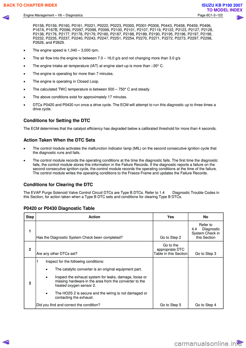
P0420 or P0430 Diagnostic Table
Step Action Yes No
1
Has the Diagnostic System Check been completed? Go to Step 2 Refer to
4.4 Diagnostic
System Check in this Section
2 Are any other DTCs set? Go to the
appropriate DTC
Table in this Section Go to Step 3
3 1 Inspect for the following conditions:
• The catalytic converter is an original equipment part.
• Inspect the exhaust system for leaks, damage, loose or
missing hardware in the area from the converter to the
heated oxygen sensor 2.
• The HO2S 2 is secure and the wiring is not damaged or
contacting the exhaust.
Did you find and correct the condition? Go to Step 5 Go to Step 4
BACK TO CHAPTER INDEX
TO MODEL INDEX
ISUZU KB P190 2007
Page 3401 of 6020
Engine Management – V6 – Diagnostics Page 6C1-2–123
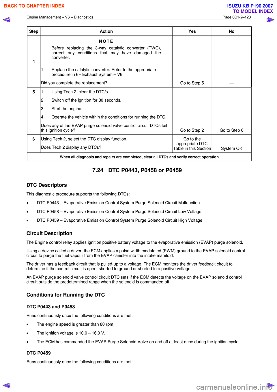
Step Action Yes No
4 NOTE
Before replacing the 3-way catalytic converter (TW C),
correct any conditions that may have damaged the
converter.
1 Replace the catalytic converter. Refer to the appropriate procedure in 6F Exhaust System – V6.
Did you complete the replacement? Go to Step 5 —
5 1 Using Tech 2, clear the DTC/s.
2 Switch off the ignition for 30 seconds.
3 Start the engine.
4 Operate the vehicle within the conditions for running the DTC.
Does any of the EVAP purge solenoid valve control circuit DTCs fail
this ignition cycle? Go to Step 2 Go to Step 6
6 Using Tech 2, select the DTC display function.
Does Tech 2 display any DTCs? Go to the
appropriate DTC
Table in this Section System OK
When all diagnosis and repairs are completed, clear all DTCs and verify correct operation
7.24 DTC P0443, P0458 or P0459
DTC Descriptors
This diagnostic procedure supports the following DTCs:
• DTC P0443 – Evaporative Emission Control System Purge Solenoid Circuit Malfunction
• DTC P0458 – Evaporative Emission Control System Purge Solenoid Circuit Low Voltage
• DTC P0459 – Evaporative Emission Control System Purge Solenoid Circuit High Voltage
Circuit Description
The Engine control relay applies ignition positive battery voltage to the evaporative emission (EVAP) purge solenoid.
Using a device called a driver, the ECM applies a pulse width modulated (PW M) ground to the EVAP solenoid control
circuit to purge the fuel vapour from the EVAP canister into the intake manifold.
The driver has a feedback circuit that is pulled-up to a voltage. The ECM monitors the driver feedback circuit to
determine if the control circuit is open, shorted to ground or shorted to a positive voltage.
An EVAP purge solenoid valve control circuit DTC sets if the ECM detects the voltage on the EVAP solenoid control
circuit outside the predetermined range when the solenoid is commanded off.
Conditions for Running the DTC
DTC P0443 and P0458
Runs continuously once the following conditions are met:
• The engine speed is greater than 80 rpm
• The ignition voltage is 10.0 – 16.0 V.
• The ECM has commanded the EVAP Purge Solenoid Valve on and off at least once during the ignition cycle.
DTC P0459
Runs continuously once the following conditions are met:
BACK TO CHAPTER INDEX
TO MODEL INDEX
ISUZU KB P190 2007
Page 3402 of 6020
Engine Management – V6 – Diagnostics Page 6C1-2–124
• The engine speed is greater than 80 rpm
• The ignition voltage is 10.0 – 16.0 V.
• The fuel system is in closed loop.
• The engine speed is above idle.
• The engine is at operating temperature.
• The ECM has commanded the EVAP Purge Solenoid Valve on and off with a duty cycle of greater than 2.5%.
Conditions for Setting the DTC
DTC P0443
The ECM detects the voltage on the EVAP solenoid control circuit is not within the predetermined range when the
solenoid is commanded off.
DTC P0458
The ECM detects the voltage on the EVAP solenoid control circuit is less than 2.6 V when the solenoid is commanded
off.
DTC P0459
The ECM detects the voltage on the EVAP solenoid control circuit is greater than 4.6 V when the solenoid is
commanded on.
Conditions for Clearing the DTC
The EVAP Purge Solenoid Valve Control Circuit DTCs are Type B DTCs. Refer to 1.4 Diagnostic Trouble Codes in
this Section, for action taken when a Type B DTC sets and conditions for clearing Type B DTCs.
Additional Information
• Refer to 6C1-1 Engine Management – V6 – General Information for details of the EVAP Purge Solenoid Valve
operation.
• For an intermittent fault condition, refer to 5.2 Intermittent Fault Conditions in this Section.
• Since fault condition in a wiring connector may trigger DTCs, always test the connectors related to this diagnostic
procedure for shorted terminals or poor wiring connection before replacing any component. Refer to 8A Electrical -
Body and Chassis for information on electrical fault diagnosis.
• To assist diagnosis, refer to 3 W iring Diagrams and Connector Charts in this Section, for the system wiring
diagram and connector charts.
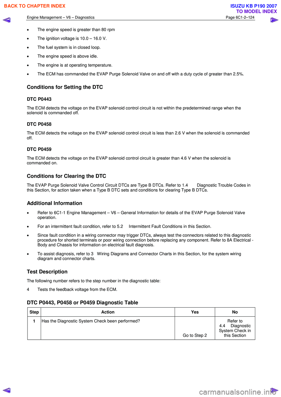
Test Description
The following number refers to the step number in the diagnostic table:
4 Tests the feedback voltage from the ECM.
DTC P0443, P0458 or P0459 Diagnostic Table
Step Action Yes No
1 Has the Diagnostic System Check been performed?
Go to Step 2 Refer to
4.4 Diagnostic
System Check in this Section
BACK TO CHAPTER INDEX
TO MODEL INDEX
ISUZU KB P190 2007
Page 3403 of 6020
Engine Management – V6 – Diagnostics Page 6C1-2–125
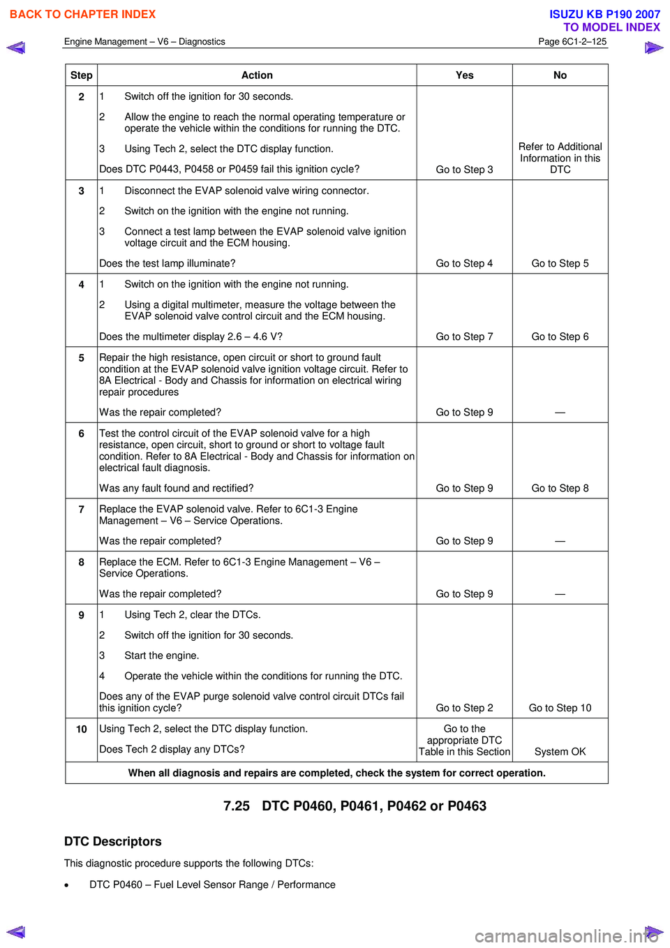
Step Action Yes No
2 1 Switch off the ignition for 30 seconds.
2 Allow the engine to reach the normal operating temperature or operate the vehicle within the conditions for running the DTC.
3 Using Tech 2, select the DTC display function.
Does DTC P0443, P0458 or P0459 fail this ignition cycle? Go to Step 3 Refer to Additional
Information in this DTC
3 1 Disconnect the EVAP solenoid valve wiring connector.
2 Switch on the ignition with the engine not running.
3 Connect a test lamp between the EVAP solenoid valve ignition voltage circuit and the ECM housing.
Does the test lamp illuminate? Go to Step 4 Go to Step 5
4 1 Switch on the ignition with the engine not running.
2 Using a digital multimeter, measure the voltage between the EVAP solenoid valve control circuit and the ECM housing.
Does the multimeter display 2.6 – 4.6 V? Go to Step 7 Go to Step 6
5 Repair the high resistance, open circuit or short to ground fault
condition at the EVAP solenoid valve ignition voltage circuit. Refer to
8A Electrical - Body and Chassis for information on electrical wiring
repair procedures
W as the repair completed? Go to Step 9 —
6 Test the control circuit of the EVAP solenoid valve for a high
resistance, open circuit, short to ground or short to voltage fault
condition. Refer to 8A Electrical - Body and Chassis for information on
electrical fault diagnosis.
W as any fault found and rectified? Go to Step 9 Go to Step 8
7 Replace the EVAP solenoid valve. Refer to 6C1-3 Engine
Management – V6 – Service Operations.
W as the repair completed? Go to Step 9 —
8 Replace the ECM. Refer to 6C1-3 Engine Management – V6 –
Service Operations.
W as the repair completed? Go to Step 9 —
9 1 Using Tech 2, clear the DTCs.
2 Switch off the ignition for 30 seconds.
3 Start the engine.
4 Operate the vehicle within the conditions for running the DTC.
Does any of the EVAP purge solenoid valve control circuit DTCs fail
this ignition cycle? Go to Step 2 Go to Step 10
10 Using Tech 2, select the DTC display function.
Does Tech 2 display any DTCs? Go to the
appropriate DTC
Table in this Section System OK
When all diagnosis and repairs are completed, check the system for correct operation.
7.25 DTC P0460, P0461, P0462 or P0463
DTC Descriptors
This diagnostic procedure supports the following DTCs:
• DTC P0460 – Fuel Level Sensor Range / Performance
BACK TO CHAPTER INDEX
TO MODEL INDEX
ISUZU KB P190 2007
Page 3404 of 6020
Engine Management – V6 – Diagnostics Page 6C1-2–126
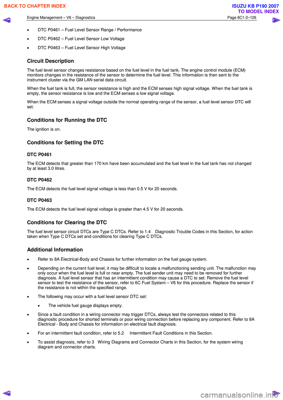
• DTC P0461 – Fuel Level Sensor Range / Performance
• DTC P0462 – Fuel Level Sensor Low Voltage
• DTC P0463 – Fuel Level Sensor High Voltage
Circuit Description
The fuel level sensor changes resistance based on the fuel level in the fuel tank. The engine control module (ECM)
monitors changes in the resistance of the sensor to determine the fuel level. This information is then sent to the
instrument cluster via the GM LAN serial data circuit.
W hen the fuel tank is full, the sensor resistance is high and the ECM senses high signal voltage. W hen the fuel tank is
empty, the sensor resistance is low and the ECM senses a low signal voltage.
W hen the ECM senses a signal voltage outside the normal operating range of the sensor, a fuel level sensor DTC will
set.
Conditions for Running the DTC
The ignition is on.
Conditions for Setting the DTC
DTC P0461
The ECM detects that greater than 170 km have been accumulated and the fuel level in the fuel tank has not changed
by at least 3.0 litres.
DTC P0462
The ECM detects the fuel level signal voltage is less than 0.5 V for 20 seconds.
DTC P0463
The ECM detects the fuel level signal voltage is greater than 4.5 V for 20 seconds.
Conditions for Clearing the DTC
The fuel level sensor circuit DTCs are Type C DTCs. Refer to 1.4 Diagnostic Trouble Codes in this Section, for action
taken when Type C DTCs set and conditions for clearing Type C DTCs.
Additional Information
• Refer to 8A Electrical-Body and Chassis for further information on the fuel gauge system.
• Depending on the current fuel level, it may be difficult to locate a malfunctioning sending unit. The malfunction may
only occur when the fuel level is full or near empty. The fuel sender unit may need to be removed for further
diagnosis. A fuel level sensor that has an intermittent condition may cause a DTC to set. Remove the fuel level
sensor to test the resistance of the sensor, refer to 6C Fuel System – V6 for this procedure. Replace the sensor if
the resistance is not within the specified range.
• The following may occur with a fuel level sensor DTC set:
• The vehicle fuel gauge displays empty.
• Since a fault condition in a wiring connector may trigger DTCs, always test the connectors related to this
diagnostic procedure for shorted terminals or poor wiring connection before replacing any component. Refer to 8A
Electrical - Body and Chassis for information on electrical fault diagnosis.
• For an intermittent fault condition, refer to 5.2 Intermittent Fault Conditions in this Section.
• To assist diagnosis, refer to 3 W iring Diagrams and Connector Charts in this Section, for the system wiring
diagram and connector charts.
BACK TO CHAPTER INDEX
TO MODEL INDEX
ISUZU KB P190 2007