2007 ISUZU KB P190 torque
[x] Cancel search: torquePage 3905 of 6020
Automatic Transmission – 4L60E – Electrical Diagnosis Page 7C2–119
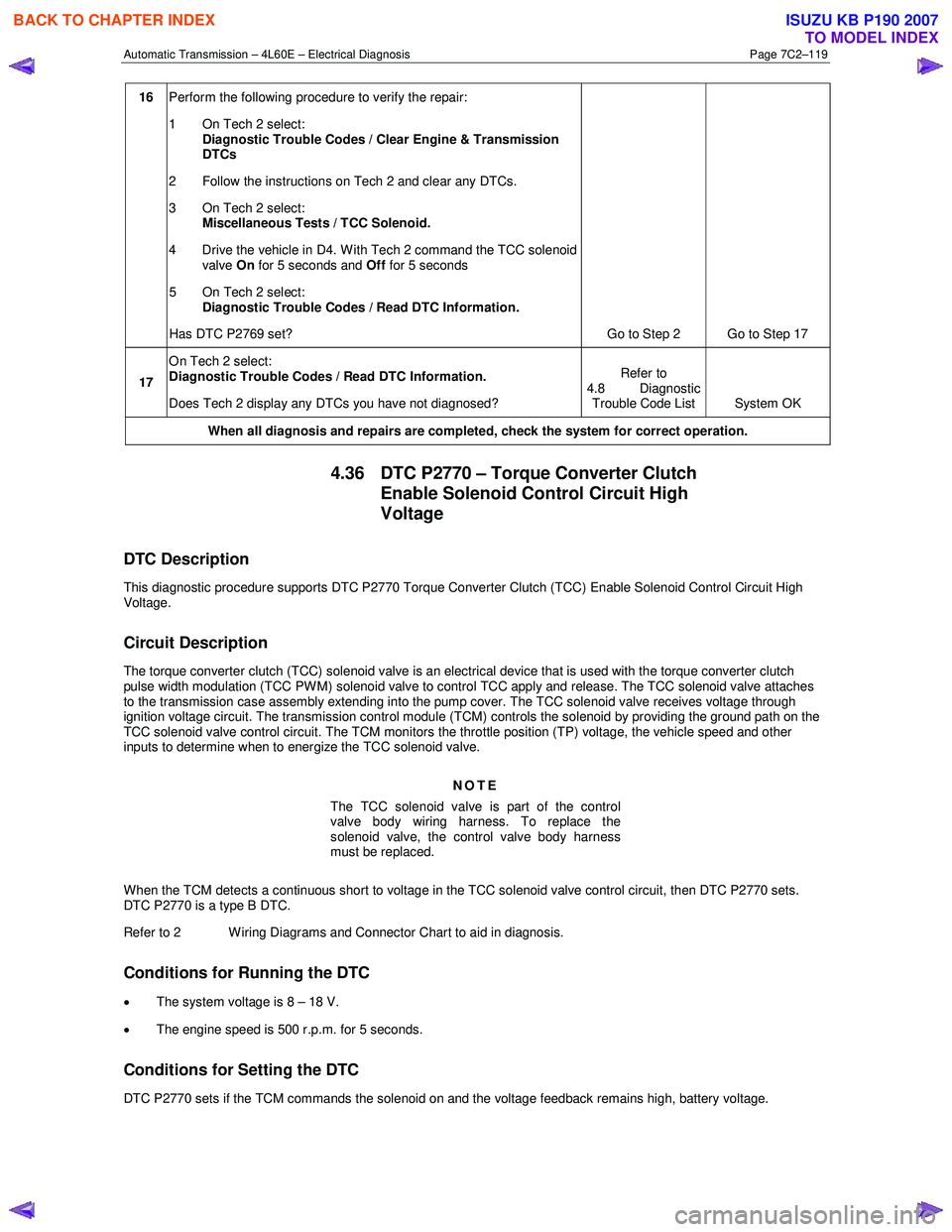
16 Perform the following procedure to verify the repair:
1 On Tech 2 select: Diagnostic Trouble Codes / Clear Engine & Transmission
DTCs
2 Follow the instructions on Tech 2 and clear any DTCs.
3 On Tech 2 select: Miscellaneous Tests / TCC Solenoid.
4 Drive the vehicle in D4. With Tech 2 command the TCC solenoid valve On for 5 seconds and Off for 5 seconds
5 On Tech 2 select:
Diagnostic Trouble Codes / Read DTC Information.
Has DTC P2769 set? Go to Step 2 Go to Step 17
17 On Tech 2 select:
Diagnostic Trouble Codes / Read DTC Information.
Does Tech 2 display any DTCs you have not diagnosed? Refer to
4.8 Diagnostic Trouble Code List System OK
When all diagnosis and repairs are completed, check the
system for correct operation.
4.36 DTC P2770 – Torque Converter Clutch
Enable Solenoid Control Circuit High
Voltage
DTC Description
This diagnostic procedure supports DTC P2770 Torque Converter Clutch (TCC) Enable Solenoid Control Circuit High
Voltage.
Circuit Description
The torque converter clutch (TCC) solenoid valve is an electrical device that is used with the torque converter clutch
pulse width modulation (TCC PWM) solenoid valve to control TCC apply and release. The TCC solenoid valve attaches
to the transmission case assembly extending into the pump cover. The TCC solenoid valve receives voltage through
ignition voltage circuit. The transmission control module (TCM) controls the solenoid by providing the ground path on the
TCC solenoid valve control circuit. The TCM monitors the throttle position (TP) voltage, the vehicle speed and other
inputs to determine when to energize the TCC solenoid valve.
NOTE
The TCC solenoid valve is part of the control
valve body wiring harness. To replace the
solenoid valve, the control valve body harness
must be replaced.
W hen the TCM detects a continuous short to voltage in the TCC solenoid valve control circuit, then DTC P2770 sets.
DTC P2770 is a type B DTC.
Refer to 2 W iring Diagrams and Connector Chart to aid in diagnosis.
Conditions for Running the DTC
• The system voltage is 8 – 18 V.
• The engine speed is 500 r.p.m. for 5 seconds.
Conditions for Setting the DTC
DTC P2770 sets if the TCM commands the solenoid on and the voltage feedback remains high, battery voltage.
BACK TO CHAPTER INDEX
TO MODEL INDEX
ISUZU KB P190 2007
Page 3915 of 6020
Automatic Transmission – 4L60E – On-vehicle Servicing Page 7C4–2
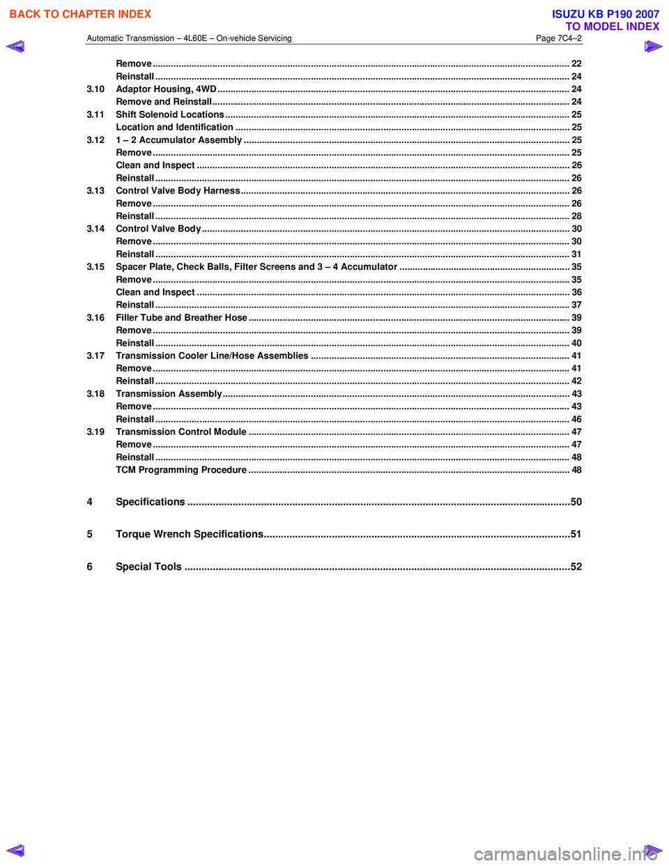
Remove ................................................................................................................................................................. 22
Reinstall ................................................................................................................................................................ 24
3.10 Adaptor Housing, 4WD ........................................................................................................................................ 24
Remove and Reinstall .......................................................................................................................................... 24
3.11 Shift Solenoid Locations ..................................................................................................................................... 25
Location and Identification .................................................................................................... ............................. 25
3.12 1 – 2 Accumulator Assembly ..................................................................................................... ......................... 25
Remove ................................................................................................................................................................. 25
Clean and Inspect ................................................................................................................................................ 26
Reinstall ................................................................................................................................................................ 26
3.13 Control Valve Body Harness ..................................................................................................... .......................... 26
Remove ................................................................................................................................................................. 26
Reinstall ................................................................................................................................................................ 28
3.14 Control Valve Body .............................................................................................................................................. 30
Remove ................................................................................................................................................................. 30
Reinstall ................................................................................................................................................................ 31
3.15 Spacer Plate, Check Balls, Filter Screens and 3 – 4 Accumulator ................................................................ .. 35
Remove ................................................................................................................................................................. 35
Clean and Inspect ................................................................................................................................................ 36
Reinstall ................................................................................................................................................................ 37
3.16 Filler Tube and Breather Hose .................................................................................................. .......................... 39
Remove ................................................................................................................................................................. 39
Reinstall ................................................................................................................................................................ 40
3.17 Transmission Cooler Line/Hose Assemblies ....................................................................................... ............. 41
Remove ................................................................................................................................................................. 41
Reinstall ................................................................................................................................................................ 42
3.18 Transmission Assembly...................................................................................................................................... 43
Remove ................................................................................................................................................................. 43
Reinstall ................................................................................................................................................................ 46
3.19 Transmission Control Module ............................................................................................................................ 47
Remove ................................................................................................................................................................. 47
Reinstall ................................................................................................................................................................ 48
TCM Programming Procedure ...................................................................................................... ...................... 48
4 Specifications .......................................................................................................................................50
5 Torque Wrench Specifications................................................................................................... .........51
6 Special Tools ........................................................................................................................................52
BACK TO CHAPTER INDEX
TO MODEL INDEX
ISUZU KB P190 2007
Page 3916 of 6020
Automatic Transmission – 4L60E – On-vehicle Servicing Page 7C4–3
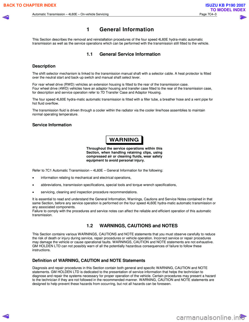
1 General Information
This Section describes the removal and reinstallation procedures of the four speed 4L60E hydra-matic automatic
transmission as well as the service operations which can be performed with the transmission still fitted to the vehicle.
1.1 General Service Information
Description
The shift selector mechanism is linked to the transmission manual shaft with a selector cable. A heat protector is fitted
over the neutral start and back-up switch and manual shaft select lever.
For rear wheel drive (RWD) vehicles an extension housing is fitted to the rear of the transmission case.
Four wheel drive (4W D) vehicles have an adaptor housing and transfer case fitted to the rear of the transmission case,
for description and service operation refer to 7D Transfer Case and Adaptor Housing.
The four speed 4L60E hydra-matic automatic transmission is fitted with a filler tube, a breather hose and a vent pipe for
hot fluid overflow.
The transmission fluid is driven through a cooler within the radiator via the cooler line/hose assemblies to maintain
normal operating temperature.
Service Information
Throughout the service operations within this
Section, when handling retaining clips, using
compressed air or cleaning fluids, wear safety
equipment to avoid personal injury.
Refer to 7C1 Automatic Transmission – 4L60E – General Information for the following:
• information relating to mechanical and electrical operations,
• abbreviations, transmission specifications, special tools and torque wrench specifications,
• servicing, cleaning and inspection procedure recommendations.
It is essential to read and understand the General Information, W arnings, Cautions and Service Notes contained in that
same Section, before any service operation is performed on the four speed 4L60E hydra-matic automatic transmission or
any associated components.
Failure to comply with the procedures and service notes can affect the reliable and efficient operation of this automatic
transmission.
1.2 WARNINGS, CAUTIONS and NOTES
This Section contains various W ARNINGS, CAUTIONS and NOTE statements that you must observe carefully to reduce
the risk of death or injury during service, repair procedures or vehicle operation. Incorrect service or repair procedures
may damage the vehicle or cause operational faults. W ARNINGS, CAUTION and NOTE statements are not exhaustive.
GM HOLDEN LTD can not possibly warn of all the potentially hazardous consequences of failure to follow these
instructions.
Definition of WARNING, CAUTION and NOTE Statements
Diagnosis and repair procedures in this Section contain both general and specific W ARNING, CAUTION and NOTE
statements. GM HOLDEN LTD is dedicated to the presentation of service information that helps the technician to
diagnose and repair the systems necessary for proper operation of the vehicle. Certain procedures may present a hazard
to the technician if they are not followed in the recommended manner. W ARNING, CAUTION and NOTE statements are
designed to help prevent these hazards from occurring, but not all hazards can be foreseen.
BACK TO CHAPTER INDEX
TO MODEL INDEX
ISUZU KB P190 2007
Page 3919 of 6020

Automatic Transmission – 4L60E – On-vehicle Servicing Page 7C4–6
6 Lift the locking lever (1) on the transmission fluid
indicator, then remove the indicator from the filler
tube (2) and check the fluid colour, condition and level.
Do not overfill the transmission. Overfilling
can cause aeration resulting in fluid loss,
shift complaints and possible damage to the
transmission.
7 If the transmission fluid level is low, add only enough of the recommended fluid until
its level shows onto the
crosshatch hot area (3) of the fluid indicator.
Figure 7C4 – 1
2.2 Reverse Flush and Flow Rate Test
It is essential to perform a reverse flush and oil cooler flow rate test after any of the following:
• the transmission is repaired or replaced,
• fluid contamination is suspected, or
• whenever the oil pump and/or torque converter is replaced.
NOTE
The reverse flush must be completed prior to
conducting a flow rate test.
Reverse Flush
1 Disconnect both cooler hose/line assemblies at the transmission and at the radiator cooler, refer to 3.17 Transmission Cooler Line/Hose Assemblies.
2 Check the cooler hose/line to radiator cooler fittings for damage, replace as required.
To avoid personal injury, wear safety glasses
when using compressed air.
3 Carefully check the radiator cooler lower fitting to see if any foreign material is evident at this point. If foreign material is found, remove it with a suitable tool and/or compressed air at a reduced pressure of approximately
345 kPa blown in the reverse direction through the cooler.
4 Using compressed air at a reduced pressure of approximately 345 kPa blown in a reverse direction, clean the cooler hose/line assemblies.
5 Reconnect the cooler outlet line to the transmission and both cooler hose/line assemblies to the radiator cooler fittings, refer to 3.17 Transmission Cooler Line/Hose Assemblies.
NOTE
Do not reconnect the cooler inlet line at the
transmission end. This line needs to be left
disconnected to perform the flow rate test.
6 Perform the flow rate test, refer to Flow Rate Test in this Section.
BACK TO CHAPTER INDEX
TO MODEL INDEX
ISUZU KB P190 2007
Page 3923 of 6020
Automatic Transmission – 4L60E – On-vehicle Servicing Page 7C4–10
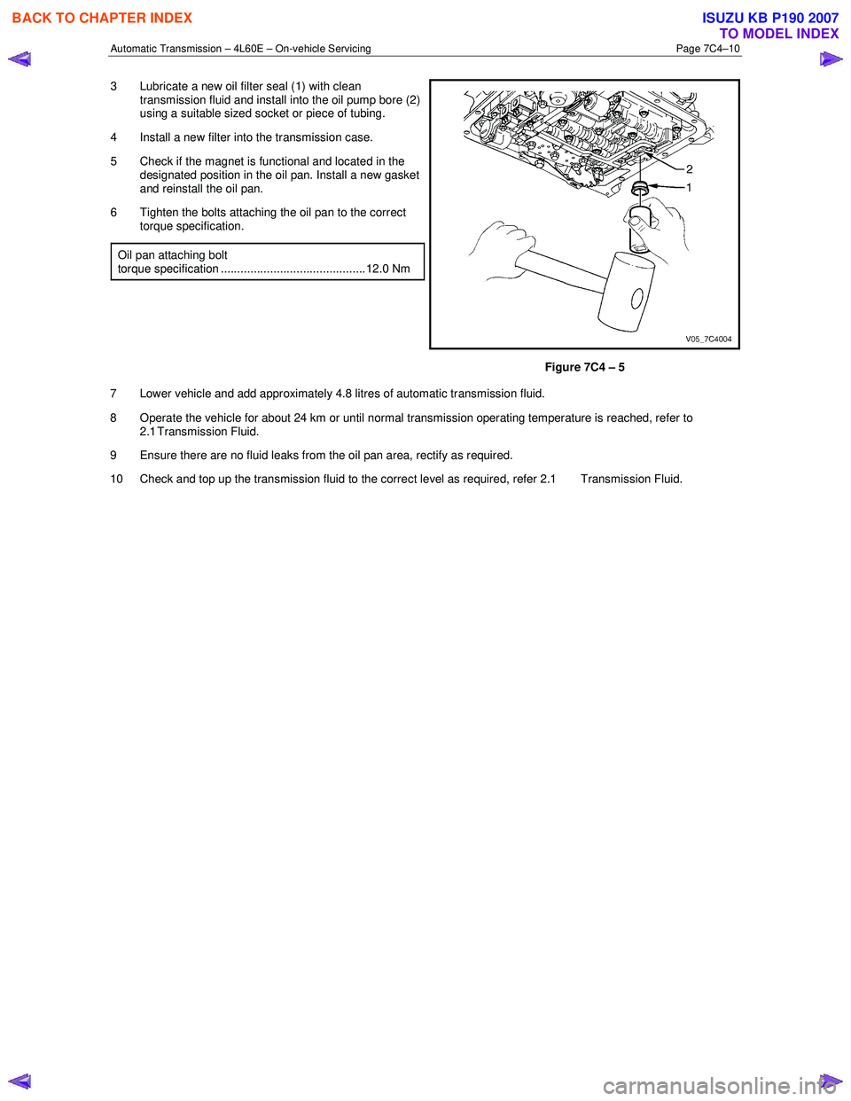
3 Lubricate a new oil filter seal (1) with clean
transmission fluid and install into the oil pump bore (2)
using a suitable sized socket or piece of tubing.
4 Install a new filter into the transmission case.
5 Check if the magnet is functional and located in the designated position in the oil pan. Install a new gasket
and reinstall the oil pan.
6 Tighten the bolts attaching the oil pan to the correct torque specification.
Oil pan attaching bolt
torque specification ............................................ 12.0 Nm
Figure 7C4 – 5
7 Lower vehicle and add approximately 4.8 litres of automatic transmission fluid.
8 Operate the vehicle for about 24 km or until normal transmission operating temperature is reached, refer to 2.1 Transmission Fluid.
9 Ensure there are no fluid leaks from the oil pan area, rectify as required.
10 Check and top up the transmission fluid to the correct level as required, refer 2.1 Transmission Fluid.
BACK TO CHAPTER INDEX
TO MODEL INDEX
ISUZU KB P190 2007
Page 3925 of 6020
Automatic Transmission – 4L60E – On-vehicle Servicing Page 7C4–12
4 Remove the knob together with the button (5) and spring (6) from the selector lever assembly (7).
5 Turn the sleeve (8) counter clockwise to remove it, make note of the number of turns required to free it.
6 Remove the harness connectors from the base plate (9).
7 Remove the upper housing (10) which is held in place by four latched fasteners.
8 Remove the attaching screw (11) and spring plate (12).
9 Remove the grooved pin (13).
10 Using a small flat blade screwdriver, gently prise the upper end of the selector cable (14) from the pin on the selector lever linkage (15).
11 Remove the selector lever assembly by pressing the rod down (lever in the N position).
12 If required, remove the lamp (16) from its socket by aligning the groove in the socket and the protruding part of the lamp.
13 If required, remove the nut (17), four places, and the shift selector base plate.
Reinstall
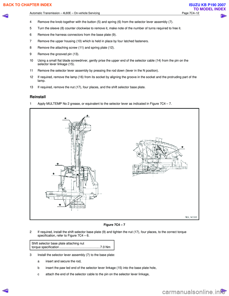
1 Apply MULTEMP No 2 grease, or equivalent to the selector lever as indicated in Figure 7C4 – 7.
Figure 7C4 – 7
2 If required, install the shift selector base plate (9) and tighten the nut (17), four places, to the correct torque specification, refer to Figure 7C4 – 6.
Shift selector base plate attaching nut
torque specification ..............................................7.0 Nm
3 Install the selector lever assembly (7) to the base plate: a insert and secure the rod,
b insert the paw led end of the selector lever linkage (15) into the base plate hole,
c attach the end of the selector cable to the pin on the selector lever linkage,
BACK TO CHAPTER INDEX
TO MODEL INDEX
ISUZU KB P190 2007
Page 3926 of 6020
Automatic Transmission – 4L60E – On-vehicle Servicing Page 7C4–13
d Install the grooved pin (13) in the selector lever.
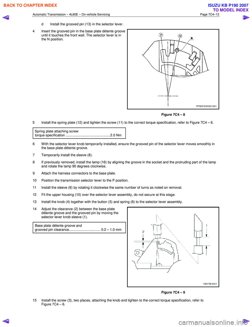
4 Insert the grooved pin in the base plate détente groove until it touches the front wall. The selector lever is in
the N position.
Figure 7C4 – 8
5 Install the spring plate (12) and tighten the screw (11) to the correct torque specification, refer to Figure 7C4 – 6.
Spring plate attaching screw
torque specification ..............................................2.0 Nm
6 W ith the selector lever knob temporarily installed, ensure the grooved pin of the selector lever moves smoothly in the base plate détente groove.
7 Temporarily install the sleeve (8).
8 If previously removed, install the lamp (16) by aligning the groove in the socket and the protruding part of the lamp and rotate the lamp 90 degrees clockwise.
9 Attach the harness connectors to the base plate.
10 Position the transmission selector lever to the P position.
11 Install the sleeve (8) by rotating it clockwise the same number of turns as noted on removal.
12 Fit the upper housing (10) over the selector lever assembly, do not secure at this stage.
13 Install the knob (4) together with the button (5) and spring (6) to the selector lever assembly.
14 Adjust the clearance (2) between the base plate détente groove and the grooved pin by moving the
selector lever knob sleeve (1).
Base plate détente groove and
grooved pin clearance................................ 0.2 – 1.0 mm
Figure 7C4 – 9
15 Install the screw (3), two places, attaching the knob and tighten to the correct torque specification, refer to Figure 7C4 – 6.
BACK TO CHAPTER INDEX
TO MODEL INDEX
ISUZU KB P190 2007
Page 3927 of 6020
Automatic Transmission – 4L60E – On-vehicle Servicing Page 7C4–14
Selector lever knob attaching screw torque specification ..............................................2.0 Nm
16 Secure the upper housing (10) to the base plate with the four latched fasteners.
17 Install the front and rear console, refer to 10 Cab.
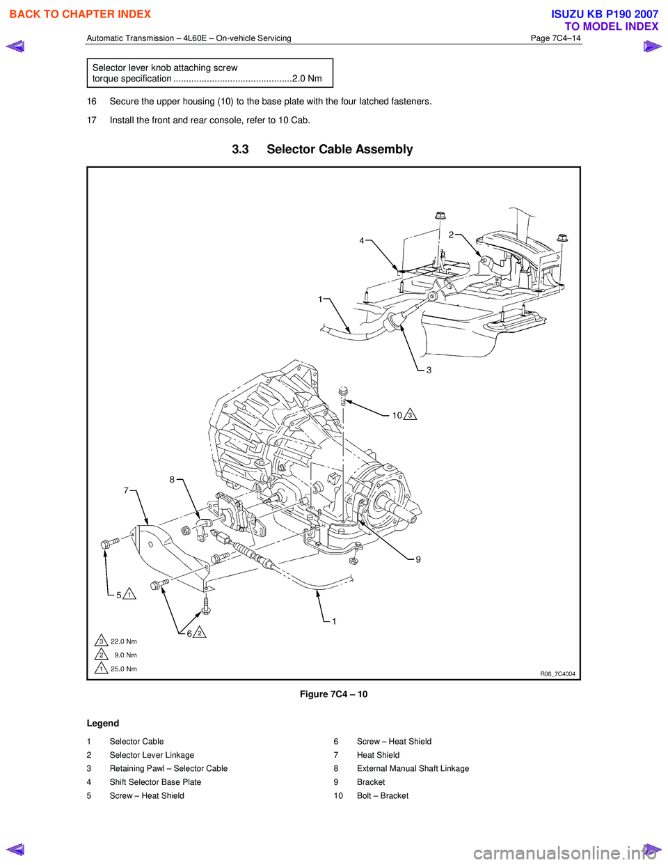
3.3 Selector Cable Assembly
Figure 7C4 – 10
Legend
1 Selector Cable
2 Selector Lever Linkage
3 Retaining Pawl – Selector Cable
4 Shift Selector Base Plate
5 Screw – Heat Shield 6 Screw – Heat Shield
7 Heat Shield
8 External Manual Shaft Linkage
9 Bracket
10 Bolt – Bracket
BACK TO CHAPTER INDEX
TO MODEL INDEX
ISUZU KB P190 2007