Page 2787 of 6020
Engine Mechanical – V6 Page 6A1–10
Page 6A1–10
1.2 Engine Components
Major Component Assemblies
Figure 6A1 – 2
Legend
1 Engine Assembly
2 Intake Manifold Assembly
3 Camshaft Cover Assembly, Left-hand
4 Camshaft Cover Assembly, Right-hand
5 Engine Front Cover Assembly
6 Oil Pan Assembly
7 Engine Flywheel
8 Engine Flywheel Bolt
9 Crankshaft Balancer
10 Crankshaft Balancer Bolt
11 Exhaust Manifold Gasket, Left-hand 12 Exhaust Manifold, Left-hand
13 Exhaust Manifold Heat Shield, Left-hand
14 Exhaust Manifold Heat Shield Bolt, Left-hand
15 Exhaust Manifold Gasket, Right-hand
16 Exhaust Manifold, Right-hand
17 Cylinder Head Exhaust Manifold Bolt
18 Exhaust Manifold Heat Shield, Right-hand
19 Exhaust Manifold Heat Shield Bolt, Right-hand
20 Ignition Coil Assembly
21 Ignition Coil Assembly Bolt
22 Spark Plug
BACK TO CHAPTER INDEX
TO MODEL INDEX
ISUZU KB P190 2007
Page 2791 of 6020
Engine Mechanical – V6 Page 6A1–14
Page 6A1–14
Camshaft Cover Assembly
Figure 6A1 – 6
Legend
1 Camshaft Cover, Left-hand
2 Camshaft Cover Gasket, Left-hand
3 Camshaft Cover, Right-hand
4 Camshaft Cover Gasket, Right-hand
5 Camshaft Cover Spark Plug Port Seal
6 Camshaft Cover Bolt
7 Camshaft Cover Bolt Insulator
8 Ignition Coil Bolt Thread Insert
9 Oil Fill Cap 10 Oil Fill O-Ring
11 Camshaft Cover PCV Fitting, Left-hand
12 Camshaft Cover PCV Fitting Orifice, Right-hand
13 Oil Fill Tube
14 Camshaft Cover PCV Fitting O-Ring, Left-hand
15 Ignition Coil
16 Ignition Coil Bolt
17 Spark Plug
BACK TO CHAPTER INDEX
TO MODEL INDEX
ISUZU KB P190 2007
Page 2792 of 6020
Engine Mechanical – V6 Page 6A1–15
Page 6A1–15
Cylinder Head Assembly
Figure 6A1 – 7
Legend
1 Cylinder Head, Left-hand
2 Cylinder Head, Right-hand
3 Cylinder Head Gasket, Left-hand
4 Cylinder Head Gasket, Right-hand
5 Cylinder Head Bolt
6 Cylinder Head Front Bolt
7 Cylinder Head Coolant Hole Threaded Plug
8 Spark Plug Sleeve
9 Cylinder Head Oil Gallery Expansion Plug
10 Exhaust Valve
11 Intake Valve
12 Valve Rocker Arm Assembly
13 Hydraulic Valve Lash Adjuster Assembly
14 Valve Stem Oil Seal 15 Valve Spring
16 Valve Spring Cap
17 Valve Stem Key
18 Cylinder Head Camshaft Front Thrust Bearing Cap
19 Camshaft Oil Seal Ring
20 Exhaust Camshaft
21 Intake Camshaft, Left-hand (bank 2)
22 Intake Camshaft, Right-hand (bank 1)
23 Exhaust Camshaft, Right-hand (bank 1)
24 Cylinder Head Camshaft Cap – Intermediate
25 Cylinder Head Camshaft Cap Bolt
26 Cylinder Head Oil Galley Check Valve
27 Engine Coolant Temperature Sensor
BACK TO CHAPTER INDEX
TO MODEL INDEX
ISUZU KB P190 2007
Page 2793 of 6020
Engine Mechanical – V6 Page 6A1–16
Page 6A1–16
Oil Pump
Figure 6A1 – 8
Legend
1 Lower Primary Timing Chain Guide
2 Lower Primary Timing Chain Guide Bolt
3 Oil Pump Housing
4 Oil Pump Cover
5 Oil Pump Gerotor Outer Ring
6 Oil Pump Gerotor Inner Ring 7 Oil Pump Cover Bolt
8 Oil Pressure Relief Valve Bore Plug
9 Oil Pressure Relief Valve Spring
10 Oil Pressure Relief Valve
11 Oil Pressure Relief Valve Bore Plug Retainer Clip
12 Oil Pump Bolt
NOTE
Oil pump components are not serviced
individually.
BACK TO CHAPTER INDEX
TO MODEL INDEX
ISUZU KB P190 2007
Page 2794 of 6020

Engine Mechanical – V6 Page 6A1–17
Page 6A1–17
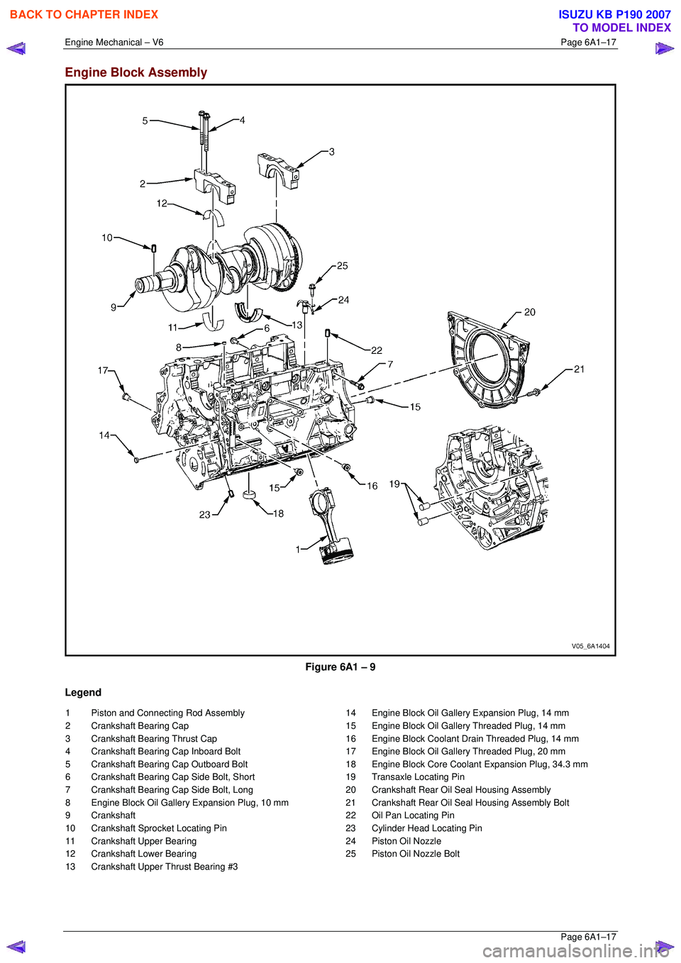
Engine Block Assembly
Figure 6A1 – 9
Legend
1 Piston and Connecting Rod Assembly
2 Crankshaft Bearing Cap
3 Crankshaft Bearing Thrust Cap
4 Crankshaft Bearing Cap Inboard Bolt
5 Crankshaft Bearing Cap Outboard Bolt
6 Crankshaft Bearing Cap Side Bolt, Short
7 Crankshaft Bearing Cap Side Bolt, Long
8 Engine Block Oil Gallery Expansion Plug, 10 mm
9 Crankshaft
10 Crankshaft Sprocket Locating Pin
11 Crankshaft Upper Bearing
12 Crankshaft Lower Bearing
13 Crankshaft Upper Thrust Bearing #3 14 Engine Block Oil Gallery Expansion Plug, 14 mm
15 Engine Block Oil Gallery Threaded Plug, 14 mm
16 Engine Block Coolant Drain Threaded Plug, 14 mm
17 Engine Block Oil Gallery Threaded Plug, 20 mm
18 Engine Block Core Coolant Expansion Plug, 34.3 mm
19 Transaxle Locating Pin
20 Crankshaft Rear Oil Seal Housing Assembly
21 Crankshaft Rear Oil Seal Housing Assembly Bolt
22 Oil Pan Locating Pin
23 Cylinder Head Locating Pin
24 Piston Oil Nozzle
25 Piston Oil Nozzle Bolt
BACK TO CHAPTER INDEX
TO MODEL INDEX
ISUZU KB P190 2007
Page 2795 of 6020
Engine Mechanical – V6 Page 6A1–18
Page 6A1–18
Pistons, Rings, Bearing and Connecting Rod
Figure 6A1 – 10
Legend
1 Connecting Rod
2 Connecting Rod Bolt
3 Connecting Rod Bush
4 Upper Connecting Rod Bearing
5 Lower Connecting Rod Bearing
6 Piston 7 Piston Pin
8 Piston Pin Retainer
9 Piston Upper Compression Ring
10 Piston Lower Compression Ring
11 Piston Oil Control Rail Ring
12 Piston Oil Control Ring Spacer
BACK TO CHAPTER INDEX
TO MODEL INDEX
ISUZU KB P190 2007
Page 2796 of 6020
Engine Mechanical – V6 Page 6A1–19
Page 6A1–19
Oil Pan Assembly
Figure 6A1 – 11
Legend
1 Oil Pan
2 Crankshaft Oil Deflector
3 Oil Pump Suction Pipe
4 Oil Pump Suction Pipe Gasket
5 Oil Pump Suction Pipe Bolt 6 Crankshaft Oil Deflector Bolt
7 Oil Pan Drain Plug
8 Oil Pan Drain Plug Sleeve
9 Engine Oil Level Sensor
BACK TO CHAPTER INDEX
TO MODEL INDEX
ISUZU KB P190 2007
Page 2797 of 6020
Engine Mechanical – V6 Page 6A1–20
Page 6A1–20
Oil Filter Assembly
Legend
1 Oil Filter Gasket
2 Oil Filter Adapter
3 Oil Filter Adapter Bolt
4 Oil Filter Element
Figure 6A1 – 12
BACK TO CHAPTER INDEX
TO MODEL INDEX
ISUZU KB P190 2007