Page 2705 of 6020

Engine Mechanical – V6 Page 6A1–226
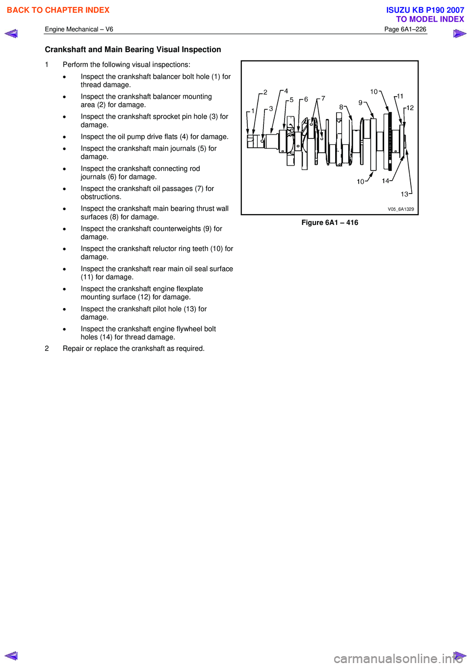
Crankshaft and Main Bearing Visual Inspection
1 Perform the following visual inspections:
• Inspect the crankshaft balancer bolt hole (1) for
thread damage.
• Inspect the crankshaft balancer mounting
area (2) for damage.
• Inspect the crankshaft sprocket pin hole (3) for
damage.
• Inspect the oil pump drive flats (4) for damage.
• Inspect the crankshaft main journals (5) for
damage.
• Inspect the crankshaft connecting rod
journals (6) for damage.
• Inspect the crankshaft oil passages (7) for
obstructions.
• Inspect the crankshaft main bearing thrust wall
surfaces (8) for damage.
• Inspect the crankshaft counterweights (9) for
damage.
• Inspect the crankshaft reluctor ring teeth (10) for
damage.
• Inspect the crankshaft rear main oil seal surface
(11) for damage.
• Inspect the crankshaft engine flexplate
mounting surface (12) for damage.
• Inspect the crankshaft pilot hole (13) for
damage.
• Inspect the crankshaft engine flywheel bolt
holes (14) for thread damage.
2 Repair or replace the crankshaft as required.
Figure 6A1 – 416
BACK TO CHAPTER INDEX
TO MODEL INDEX
ISUZU KB P190 2007
Page 2709 of 6020

Engine Mechanical – V6 Page 6A1–230
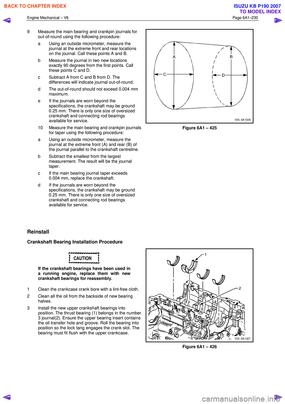
9 Measure the main bearing and crankpin journals for
out-of-round using the following procedure:
a Using an outside micrometer, measure the journal at the extreme front and rear locations
on the journal. Call these points A and B.
b Measure the journal in two new locations exactly 90 degrees from the first points. Call
these points C and D.
c Subtract A from C and B from D. The differences will indicate journal out-of-round.
d The out-of-round should not exceed 0.004 mm maximum.
e If the journals are worn beyond the specifications, the crankshaft may be ground
0.25 mm. There is only one size of oversized
crankshaft and connecting rod bearings
available for service.
10 Measure the main bearing and crankpin journals for taper using the following procedure:
a Using an outside micrometer, measure the journal at the extreme front (A) and rear (B) of
the journal parallel to the crankshaft centreline.
b Subtract the smallest from the largest measurement. The result will be the journal
taper.
c If the main bearing journal taper exceeds 0.004 mm, replace the crankshaft.
d If the journals are worn beyond the specifications, the crankshaft may be ground
0.25 mm. There is only one size of oversized
crankshaft and connecting rod bearings
available for service.
Figure 6A1 – 425
Reinstall
Crankshaft Bearing Installation Procedure
CAUTION
If the crankshaft bearings have been used in
a running engine, replace them with new
crankshaft bearings for reassembly.
1 Clean the crankcase crank bore with a lint-free cloth.
2 Clean all the oil from the backside of new bearing halves.
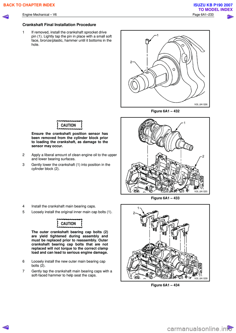
3 Install the new upper crankshaft bearings into position. The thrust bearing (1) belongs in the number
3 journal(2). Ensure the upper bearing insert contains
the oil transfer hole and groove. Roll the bearing into
position so the lock tang engages the crank slot. The
bearing must fit flush with the upper crankcase.
Figure 6A1 – 426
BACK TO CHAPTER INDEX
TO MODEL INDEX
ISUZU KB P190 2007
Page 2712 of 6020

Engine Mechanical – V6 Page 6A1–233
Crankshaft Final Installation Procedure
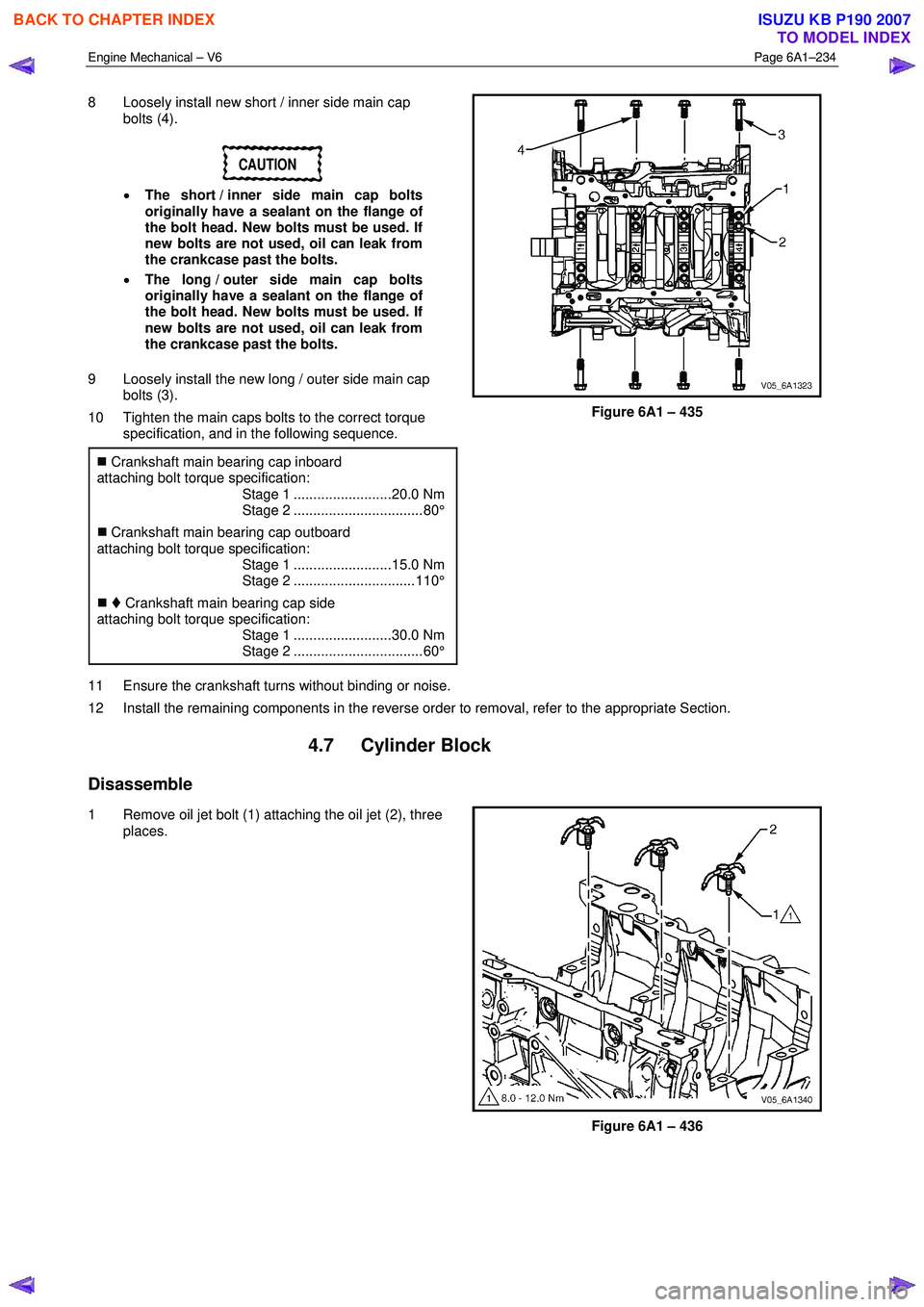
1 If removed, install the crankshaft sprocket drive
pin (1). Lightly tap the pin in place with a small soft
face, bronze/plastic, hammer until it bottoms in the
hole.
Figure 6A1 – 432
CAUTION
Ensure the crankshaft position sensor has
been removed from the cylinder block prior
to loading the crankshaft, as damage to the
sensor may occur.
2
Apply a liberal amount of clean engine oil to the upper
and lower bearing surfaces.
3 Gently lower the crankshaft (1) into position in the cylinder block (2).
Figure 6A1 – 433
4 Install the crankshaft main bearing caps.
5 Loosely install the original inner main cap bolts (1).
CAUTION
The outer crankshaft bearing cap bolts (2)
are yield tightened during assembly and
must be replaced prior to reassembly. Outer
crankshaft bearing cap bolts that are not
replaced will not torque to the correct clamp
load and can lead to serious engine damage.
6 Loosely install the new outer main bearing cap bolts (2).
7 Gently tap the crankshaft main bearing caps with a soft-faced hammer to help seat the caps.
Figure 6A1 – 434
BACK TO CHAPTER INDEX
TO MODEL INDEX
ISUZU KB P190 2007
Page 2713 of 6020

Engine Mechanical – V6 Page 6A1–234
8 Loosely install new short / inner side main cap
bolts (4).
CAUTION
• The short / inner side main cap bolts
originally have a sealant on the flange of
the bolt head. New bolts must be used. If
new bolts are not used, oil can leak from
the crankcase past the bolts.
• The long / outer side main cap bolts
originally have a sealant on the flange of
the bolt head. New bolts must be used. If
new bolts are not used, oil can leak from
the crankcase past the bolts.
9 Loosely install the new long / outer side main cap bolts (3).
10 Tighten the main caps bolts to the correct torque specification, and in the following sequence.
�„ Crankshaft main bearing cap inboard
attaching bolt torque specification:
Stage 1 .........................20.0 Nm
Stage 2 ................................. 80°
�„ Crankshaft main bearing cap outboard
attaching bolt torque specification:
Stage 1 .........................15.0 Nm
Stage 2 ............................... 110°
�„ Crankshaft main bearing cap side
attaching bolt torque specification:
Stage 1 .........................30.0 Nm
Stage 2 ................................. 60°
Figure 6A1 – 435
11 Ensure the crankshaft turns without binding or noise.
12 Install the remaining components in the reverse order to removal, refer to the appropriate Section.
4.7 Cylinder Block
Disassemble
1 Remove oil jet bolt (1) attaching the oil jet (2), three places.
Figure 6A1 – 436
BACK TO CHAPTER INDEX
TO MODEL INDEX
ISUZU KB P190 2007
Page 2714 of 6020
Engine Mechanical – V6 Page 6A1–235
2 Remove the right-hand front oil pan rail oil gallery
expansion plug (1).
Figure 6A1 – 437
3 Remove the cylinder block-to-oil pan alignment dowels (1).
Figure 6A1 – 438
4 Remove the right-hand side M14 oil gallery threaded plug (1).
Figure 6A1 – 439
BACK TO CHAPTER INDEX
TO MODEL INDEX
ISUZU KB P190 2007
Page 2715 of 6020
Engine Mechanical – V6 Page 6A1–236
5 Remove the right-hand side M14 coolant drain
threaded plug (1).
Figure 6A1 – 440
6 Remove the rear M14 oil gallery threaded plug (1).
Figure 6A1 – 441
7 Remove the left-hand side M14 coolant drain threaded plug (1).
Figure 6A1 – 442
BACK TO CHAPTER INDEX
TO MODEL INDEX
ISUZU KB P190 2007
Page 2716 of 6020
Engine Mechanical – V6 Page 6A1–237
8 Remove the left-hand side M20 oil gallery threaded
plug (1).
Figure 6A1 – 443
CAUTION
Do not force coolant expansion plugs
downwards during removal procedure as the
cylinder block will be damaged.
9 Remove the coolant expansion plugs (1).
Figure 6A1 – 444
10 Remove the cylinder block-to-transmission alignment dowels (1).
Figure 6A1 – 445
BACK TO CHAPTER INDEX
TO MODEL INDEX
ISUZU KB P190 2007
Page 2717 of 6020
Engine Mechanical – V6 Page 6A1–238
11 Remove the front oil gallery expansion plug (1).
Figure 6A1 – 446
12 Remove the cylinder block-to-cylinder head alignment dowels (1).
Figure 6A1 – 447
Clean
1 Remove all thread sealant, gasket material or sealant using a commercially available plastic or wood scraper.
2 Clean all the following areas with a suitable solvent:
• sealing surfaces,
• cooling passages,
• oil passages, and
• bearing journals.
3 Clean all threaded and through holes with a suitable solvent.
Safety glasses must be worn when using
compressed air.
4 Dry the engine block with compressed air.
BACK TO CHAPTER INDEX
TO MODEL INDEX
ISUZU KB P190 2007