2007 ISUZU KB P190 DTC CHECK
[x] Cancel search: DTC CHECKPage 4076 of 6020
7A2-110 TRANSMISSION CONTROL SYSTEM (AW30–40LE)
Conditions For Clearing The DTC
• The DTC can be cleared from the TCM history by
using a scan tool.
• The DTC will be cleared from history when the vehicle has achieved 40 warm-up cycles without a
failure reported.
•
After more than 1 second has elapsed after the
ignition key has been turned “ON”, short between
No.11 and No.4 (ground) of DLC (Data Link
Connector). Then, after 1 second, but within 6
seconds, discontinue shorting.
Diagnostic Aids
• Inspect the wiring for poor electrical connection at the
TCM. Look for possible bent, backed out, deformed
or damaged terminals. Check for weak terminal
tension as well. Also check for a chafed wire that
could short to bare metal or other wiring. Inspect for a
broken wire inside the insulation.
• W hen diagnosing for a possible intermittent short o
r
open condition, move the wiring harness while
observing test equipment for a change.
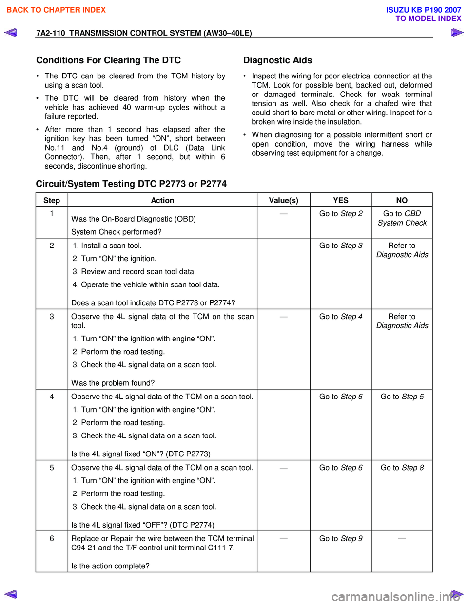
Circuit/System Testing DTC P2773 or P2774
Step Action Value(s) YES NO
1
W as the On-Board Diagnostic (OBD)
System Check performed? — Go to
Step 2 Go to OBD
System Check
2 1. Install a scan tool.
2. Turn “ON” the ignition.
3. Review and record scan tool data.
4. Operate the vehicle within scan tool data.
Does a scan tool indicate DTC P2773 or P2774? — Go to
Step 3 Refer to
Diagnostic Aids
3 Observe the 4L signal data of the TCM on the scan tool.
1. Turn “ON” the ignition with engine “ON”.
2. Perform the road testing.
3. Check the 4L signal data on a scan tool.
W as the problem found? — Go to
Step 4 Refer to
Diagnostic Aids
4 Observe the 4L signal data of the TCM on a scan tool.
1. Turn “ON” the ignition with engine “ON”.
2. Perform the road testing.
3. Check the 4L signal data on a scan tool.
Is the 4L signal fixed “ON”? (DTC P2773) — Go to
Step 6 Go to Step 5
5 Observe the 4L signal data of the TCM on a scan tool.
1. Turn “ON” the ignition with engine “ON”.
2. Perform the road testing.
3. Check the 4L signal data on a scan tool.
Is the 4L signal fixed “OFF”? (DTC P2774) — Go to
Step 6 Go to Step 8
6 Replace or Repair the wire between the TCM terminal
C94-21 and the T/F control unit terminal C111-7.
Is the action complete? — Go to
Step 9 —
BACK TO CHAPTER INDEX
TO MODEL INDEX
ISUZU KB P190 2007
Page 4079 of 6020
TRANSMISSION CONTROL SYSTEM (AW30–40LE) 7A2-113
(2) All of the following conditions are met.
• Device Control is not operating.
• Disable Normal Communication is receiving
enable.
• DTC Clear is not operating.
The following condition at ignition “OFF” form “ON” is
detected seven times in total in 1 cycle.
• Receiving BUS “OFF” information from CAN
controller.
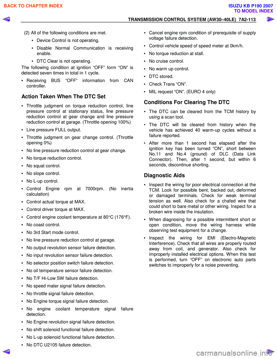
Action Taken When The DTC Set
• Throttle judgment on torque reduction control, line
pressure control at stationary status, line pressure
reduction control at gear change and line pressure
reduction control at garage. (Throttle opening 100%)
• Line pressure FULL output.
• Throttle judgment on gear change control. (Throttle
opening 0%)
• No line pressure reduction control at gear change.
• No torque reduction control.
• No squat control.
• No slope control.
• No L-up control.
• Control Engine rpm at 7000rpm. (No inertia
calculation)
• Control actual torque at MAX.
• Control driver torque at MAX.
• Control engine coolant temperature at 80 °C (176 °F).
• No coast control.
• No 3rd Start mode control.
• No line pressure reduction control at garage.
• No output revolution sensor failure detection.
• No input revolution sensor failure detection.
• No selector position switch failure detection.
• No oil temperature sensor failure detection.
• No T/F Hi-Low SW failure detection.
• No speed mater signal failure detection.
• No throttle signal failure detection.
• No Engine torque signal failure detection.
• No engine coolant temperature signal failure
detection.
• No Engine revolution signal failure detection.
• No shift solenoid functional failure detection.
• No L-up solenoid functional failure detection.
• No DTC U2105 failure detection.
• Cancel engine rpm condition of prerequisite of suppl
y
voltage failure detection.
• Control vehicle speed of speed meter at 0km/h.
• No torque reduction at stall.
• No cruise control.
• No warm up control.
• DTC stored.
• Check Trans “ON”.
• MIL request “ON”. (EURO 4 only)
Conditions For Clearing The DTC
• The DTC can be cleared from the TCM history by
using a scan tool.
• The DTC will be cleared from history when the vehicle has achieved 40 warm-up cycles without a
failure reported.
•
After more than 1 second has elapsed after the
ignition key has been turned “ON”, short between
No.11 and No.4 (ground) of DLC (Data Link
Connector). Then, after 1 second, but within 6
seconds, discontinue shorting.
Diagnostic Aids
• Inspect the wiring for poor electrical connection at the
TCM. Look for possible bent, backed out, deformed
or damaged terminals. Check for weak terminal
tension as well. Also check for a chafed wire that
could short to bare metal or other wiring. Inspect for a
broken wire inside the insulation.
• W hen diagnosing for a possible intermittent short o
r
open condition, move the wiring harness while
observing test equipment for a change.
• Inspect the wiring for EMI (Electro-Magnetic
Interference). Check that all wires are properly routed
away from coil, and generator. Also check fo
r
improperly installed electrical options. W hen this test
is performed, turn “OFF” on electronic auto parts
switches to improperly for a noise preventing.
BACK TO CHAPTER INDEX
TO MODEL INDEX
ISUZU KB P190 2007
Page 4080 of 6020
7A2-114 TRANSMISSION CONTROL SYSTEM (AW30–40LE)
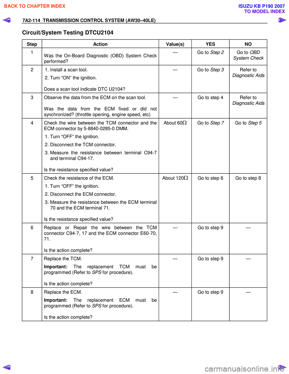
Circuit/System Testing DTCU2104
Step Action Value(s) YES NO
1
W as the On-Board Diagnostic (OBD) System Check
performed? — Go to
Step 2 Go to OBD
System Check
2 1. Install a scan tool.
2. Turn “ON” the ignition.
Does a scan tool indicate DTC U2104? — Go to
Step 3 Refer to
Diagnostic Aids
3 Observe the data from the ECM on the scan tool.
W as the data from the ECM fixed or did not
synchronized? (throttle opening, engine speed, etc) — Go to step 4 Refer to
Diagnostic Aids
4 Check the wire between the TCM connector and the ECM connector by 5-8840-0285-0 DMM.
1. Turn “OFF” the ignition.
2. Disconnect the TCM connector.
3. Measure the resistance between terminal C94-7
and terminal C94-17.
Is the resistance specified value? About 60Ω Go to
Step 7 Go to Step 5
5 Check the resistance of the ECM.
1. Turn “OFF” the ignition.
2. Disconnect the ECM connector.
3. Measure the resistance between the ECM terminal
70 and the ECM terminal 71.
Is the resistance specified value? About 120ΩGo to step 6 Go to step 8
6 Replace or Repair the wire between the TCM
connector C94-7, 17 and the ECM connector E60-70,
71.
Is the action complete? — Go to step 9 —
7 Replace the TCM.
Important: The replacement TCM must be
programmed (Refer to SPS for procedure).
Is the action complete? — Go to step 9 —
8 Replace the ECM.
Important: The replacement ECM must be
programmed (Refer to SPS for procedure).
Is the action complete? — Go to step 9 —
BACK TO CHAPTER INDEX
TO MODEL INDEX
ISUZU KB P190 2007
Page 4083 of 6020
TRANSMISSION CONTROL SYSTEM (AW30–40LE) 7A2-117
(3) All of the following conditions are met.
• Device Control is not operating.
• Disable Normal Communication is receiving
enable.
• DTC Clear is not operating.
(4) DTC U2104 is not detecting failure or not deciding failure.
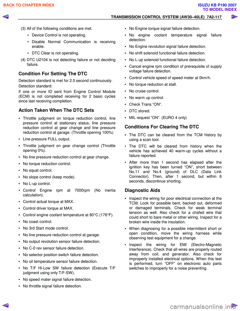
Condition For Setting The DTC
Detection standard is met for 2.5 second continuously.
Detection standard:
If one or more ID sent from Engine Control Module
(ECM) is not completed receiving for 2 basic cycles
since last receiving completion.
Action Taken When The DTC Sets
• Throttle judgment on torque reduction control, line
pressure control at stationary status, line pressure
reduction control at gear change and line pressure
reduction control at garage. (Throttle opening 100%)
• Line pressure FULL output.
• Throttle judgment on gear change control (Throttle
opening 0%).
• No line pressure reduction control at gear change.
• No torque reduction control.
• No squat control.
• No slope control (keep mode).
• No L-up control.
• Control Engine rpm at 7000rpm (No inertia
calculation).
• Control actual torque at MAX.
• Control driver torque at MAX.
• Control engine coolant temperature at 80 °C (176 °F).
• No coast control.
• No 3rd Start mode control.
• No line pressure reduction control at garage.
• No output revolution sensor failure detection.
• No C-0 rev sensor failure detection.
• No selector position switch failure detection.
• No oil temperature sensor failure detection.
• No T/F Hi-Low SW failure detection (Execute T/F
judgment using only T/F-SW ).
• No speed mater signal failure detection.
• No throttle signal failure detection.
• No Engine torque signal failure detection.
• No engine coolant temperature signal failure
detection.
• No Engine revolution signal failure detection.
• No shift solenoid functional failure detection.
• No L-up solenoid functional failure detection.
• Cancel engine rpm condition of prerequisite of suppl
y
voltage failure detection.
• Control vehicle speed of speed meter at 0km/h.
• No torque reduction at stall.
• No cruise control.
• No warm up control.
• Check Trans “ON”.
• DTC stored.
• MIL request “ON”. (EURO 4 only)
Conditions For Clearing The DTC
• The DTC can be cleared from the TCM history by
using a scan tool.
• The DTC will be cleared from history when the vehicle has achieved 40 warm-up cycles without a
failure reported.
• After more than 1 second has elapsed after the ignition key has been turned “ON”, short between
No.11 and No.4 (ground) of DLC (Data Link
Connector). Then, after 1 second, but within 6
seconds, discontinue shorting.
Diagnostic Aids
• Inspect the wiring for poor electrical connection at the
TCM. Look for possible bent, backed out, deformed
or damaged terminals. Check for weak terminal
tension as well. Also check for a chafed wire that
could short to bare metal or other wiring. Inspect for a
broken wire inside the insulation.
• W hen diagnosing for a possible intermittent short o
r
open condition, move the wiring harness while
observing test equipment for a change.
• Inspect the wiring for EMI (Electro-Magnetic
Interference). Check that all wires are properly routed
away from coil, and generator. Also check fo
r
improperly installed electrical options. W hen this test
is performed, turn “OFF” on electronic auto parts
switches to improperly for a noise preventing.
BACK TO CHAPTER INDEX
TO MODEL INDEX
ISUZU KB P190 2007
Page 4084 of 6020
7A2-118 TRANSMISSION CONTROL SYSTEM (AW30–40LE)
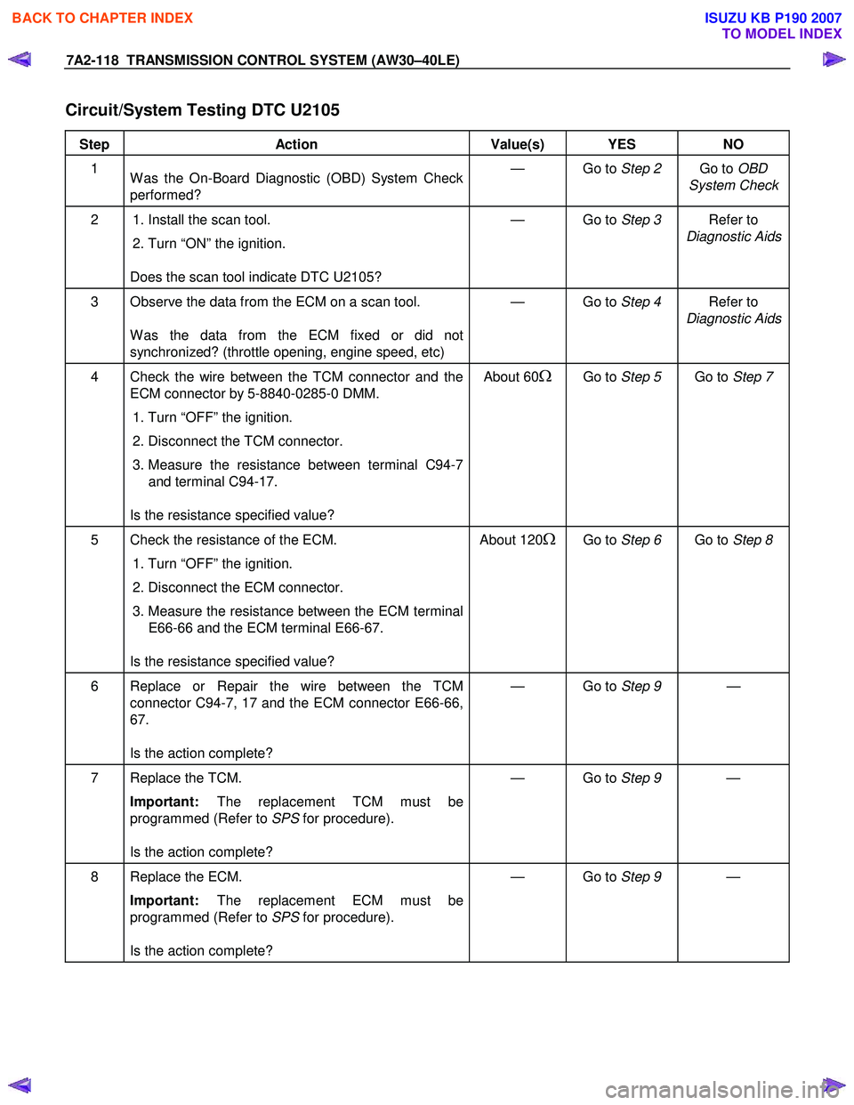
Circuit/System Testing DTC U2105
Step Action Value(s) YES NO
1
W as the On-Board Diagnostic (OBD) System Check
performed? — Go to
Step 2 Go to OBD
System Check
2 1. Install the scan tool.
2. Turn “ON” the ignition.
Does the scan tool indicate DTC U2105? — Go to
Step 3 Refer to
Diagnostic Aids
3 Observe the data from the ECM on a scan tool.
W as the data from the ECM fixed or did not
synchronized? (throttle opening, engine speed, etc) — Go to
Step 4 Refer to
Diagnostic Aids
4 Check the wire between the TCM connector and the ECM connector by 5-8840-0285-0 DMM.
1. Turn “OFF” the ignition.
2. Disconnect the TCM connector.
3. Measure the resistance between terminal C94-7
and terminal C94-17.
Is the resistance specified value? About 60Ω Go to
Step 5 Go to Step 7
5 Check the resistance of the ECM.
1. Turn “OFF” the ignition.
2. Disconnect the ECM connector.
3. Measure the resistance between the ECM terminal
E66-66 and the ECM terminal E66-67.
Is the resistance specified value? About 120ΩGo to
Step 6 Go to Step 8
6 Replace or Repair the wire between the TCM
connector C94-7, 17 and the ECM connector E66-66,
67.
Is the action complete? — Go to
Step 9 —
7 Replace the TCM.
Important: The replacement TCM must be
programmed (Refer to SPS for procedure).
Is the action complete? — Go to
Step 9 —
8 Replace the ECM.
Important: The replacement ECM must be
programmed (Refer to SPS for procedure).
Is the action complete? — Go to
Step 9 —
BACK TO CHAPTER INDEX
TO MODEL INDEX
ISUZU KB P190 2007
Page 4285 of 6020

TRANSMISSION CONTROL SYSTEM (JR405E) 7A2-1
TRANSMISSION
TRANSMISSION CONTROL SYSTEM (JR405E)
This manual conforms when Scan Tool of ISO CAN Base Software is used.
TABLE OF CONTENTS
Specifications ...................................................... 7A2-2Transmission General Specifications ............... 7A2-2
Transmission Fluid Temperature vs. Resistance..... 7A2-3
Clutch, Brake, Solenoid and Pressure Switch Logic........ 7A2-4
Diagnostic Trouble Code (DTC) List ................ 7A2-5
Schematic and Routing Diagrams....................... 7A2-6 Transmission Controls Schematics .................. 7A2-6
Component Locator........................................... 7A2-13 Transmission Controls Component Views ..... 7A2-13
Transmission Control Module (TCM) Connector End Views ................................... 7A2-17
Transmission Control Connector End Views.. 7A2-18
Diagnostic Information and Procedures ............ 7A2-21
Diagnostic Starting Point - Transmission Controls......... 7A2-21
Diagnostic System Check - Transmission Controls....... 7A2-22
Scan Tool Data List ........................................ 7A2-24
Scan Tool Data Definitions............................. 7A2-25
Scan Tool Output Controls ............................. 7A2-27
Scan Tool Does Not Power Up ...................... 7A2-28
Scan Tool Does Not Communicate with Keyword Device .................................... 7A2-29
Lost Communication with The Transmission Control Module (TCM)
.... 7A2-31
DTC P0560 (Flash Code 16).......................... 7A2-33
DTC P0602 .................................................... 7A2-35
DTC P0705 (Flash Code 17).......................... 7A2-36
DTC P0710 (Flash Code 15).......................... 7A2-40
DTC P0717 (Flash Code 14).......................... 7A2-44
DTC P0722 (Flash Code 11).......................... 7A2-47
DTC P0727 (Flash Code 13).......................... 7A2-50
DTC P0731, P0732, P0733 or P0734 (Flash Code 41, 42, 43 or 44)....................... 7A2-52
DTC P0748 (Flash Code 35).......................... 7A2-55
DTC P0753 (Flash Code 31).......................... 7A2-58
DTC P0758 (Flash Code 32).......................... 7A2-61
DTC P0763 (Flash Code 33).......................... 7A2-64
DTC P0768 (Flash Code 34).......................... 7A2-67
DTC P1120 (Flash Code 22).......................... 7A2-70
DTC P1750 (Flash Code 51).......................... 7A2-71
DTC P1755 (Flash Code 52).......................... 7A2-73
DTC P1853 (Flash Code 26).......................... 7A2-75
DTC P1858 (Flash Code 27).......................... 7A2-78
DTC P1860 (Flash Code 36).......................... 7A2-81
DTC P1863 (Flash Code 28).......................... 7A2-84
DTC P1875 (Flash Code 25).......................... 7A2-87
Check Trans Lamp Inoperative, Always On or Always Blinking ...................... 7A2-89
Symptoms - Transmission Controls .................. 7A2-92 Symptoms - Transmission Controls ............... 7A2-92
Intermittent Conditions ................................... 7A2-93 Vehicle Does Not Run .................................... 7A2-95
Trouble at Starting.......................................... 7A2-95
Faulty Gearshift .............................................. 7A2-95
Faulty Shift Pattern......................................... 7A2-95
No or Error Gearshift ...................................... 7A2-95
Faulty Operation During Running................... 7A2-95
Faulty Operation in Stopping.......................... 7A2-95
Faulty Lock Up ............................................... 7A2-95
No Lock Up .................................................... 7A2-95
Transmission Fluid Leak ................................ 7A2-95
Others ............................................................ 7A2-95
Test Instructions .............................................. 7A2-121 Line Pressure Test ....................................... 7A2-121
Stall Test ...................................................... 7A2-123
Time Lag Test .............................................. 7A2-124
Road Test..................................................... 7A2-125
TCM Signal Test .......................................... 7A2-134
Repair Instructions .......................................... 7A2-139
Transmission Controls Module (TCM) Replacement.... 7A2-139
Service Programming System (SPS) Description........ 7A2-139
Service Programming System (SPS) (Remote Procedure)......................... 7A2-140
Service Programming System (SPS) (Pass-Thru Procedure)..................... 7A2-141
Description and Operation .............................. 7A2-143 Transmission Identification Information........ 7A2-143
Transmission General Description ............... 7A2-143
Transmission Component Description ......... 7A2-144
Transmission Control System Description ... 7A2-152
Transmission Power Flow Description ......... 7A2-161
Special Tools and Equipment ......................... 7A2-170 Special Tools and Equipment ...................... 7A2-170
BACK TO CHAPTER INDEX
TO MODEL INDEX
ISUZU KB P190 2007
Page 4305 of 6020
TRANSMISSION CONTROL SYSTEM (JR405E) 7A2-21
Diagnostic Information and Procedures
Diagnostic Starting Point - Transmission Controls
Begin the system diagnosis with Diagnostic System
Check - Transmission Controls. The Diagnostic System
Check - Transmission Controls will provide the
following information:
• The identification of the control modules which command the system.
• The ability of the control modules to communicate through the serial data circuit.
• The identification of any stored diagnostic trouble codes (DTCs) and the their statuses.
The use of the Diagnostic System Check -
Transmission Controls will identify the correct
procedure for diagnosing the system and where the
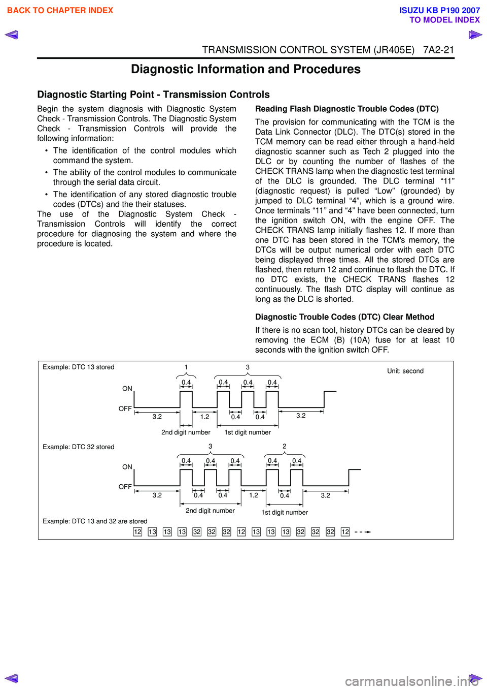
procedure is located. Reading Flash Diagnostic Trouble Codes (DTC)
The provision for communicating with the TCM is the
Data Link Connector (DLC). The DTC(s) stored in the
TCM memory can be read either through a hand-held
diagnostic scanner such as Tech 2 plugged into the
DLC or by counting the number of flashes of the
CHECK TRANS lamp when the diagnostic test terminal
of the DLC is grounded. The DLC terminal “11”
(diagnostic request) is pulled “Low” (grounded) by
jumped to DLC terminal “4”, which is a ground wire.
Once terminals “11” and “4” have been connected, turn
the ignition switch ON, with the engine OFF. The
CHECK TRANS lamp initially flashes 12. If more than
one DTC has been stored in the TCM's memory, the
DTCs will be output numerical order with each DTC
being displayed three times. All the stored DTCs are
flashed, then return 12 and continue to flash the DTC. If
no DTC exists, the CHECK TRANS flashes 12
continuously. The flash DTC display will continue as
long as the DLC is shorted.
Diagnostic Trouble Codes (DTC) Clear Method
If there is no scan tool, history DTCs can be cleared by
removing the ECM (B) (10A) fuse for at least 10
seconds with the ignition switch OFF.
Unit: second
131313323232121313133232321212
Example: DTC 13 stored
ON
OFF
Example: DTC 32 stored
Example: DTC 13 and 32 are stored
ON
OFF 3
1
0.40.40.40.4
32
0.40.40.40.40.4
2nd digit number1st digit number
3.23.20.40.40.41.2
2nd digit number 1st digit number
0.40.41.23.23.2
BACK TO CHAPTER INDEX
TO MODEL INDEX
ISUZU KB P190 2007
Page 4306 of 6020
7A2-22 TRANSMISSION CONTROL SYSTEM (JR405E)
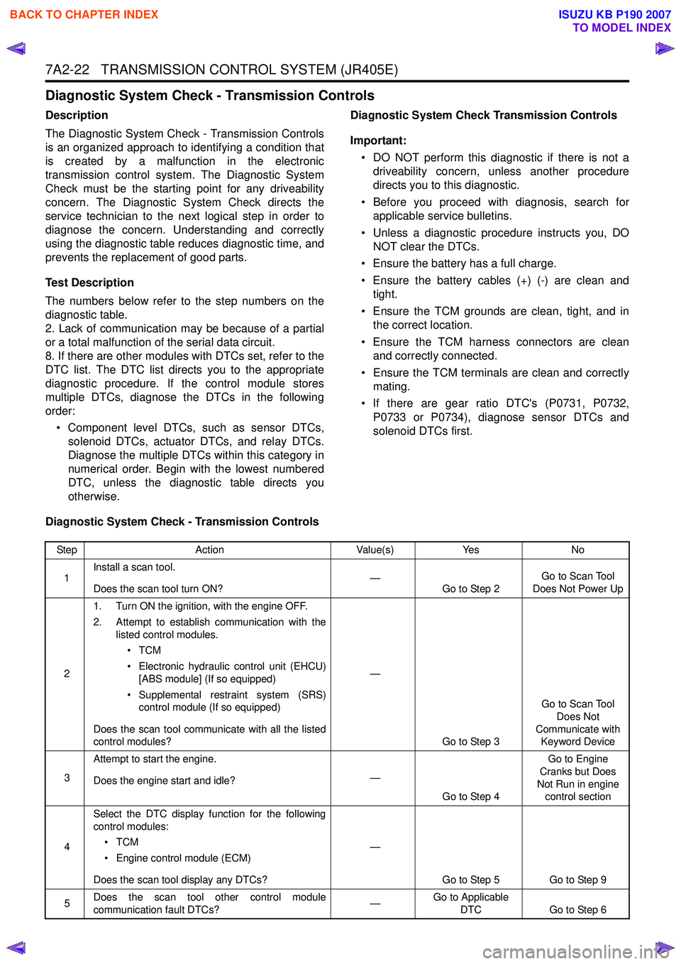
Diagnostic System Check - Transmission Controls
Description
The Diagnostic System Check - Transmission Controls
is an organized approach to identifying a condition that
is created by a malfunction in the electronic
transmission control system. The Diagnostic System
Check must be the starting point for any driveability
concern. The Diagnostic System Check directs the
service technician to the next logical step in order to
diagnose the concern. Understanding and correctly
using the diagnostic table reduces diagnostic time, and
prevents the replacement of good parts.
Test Description
The numbers below refer to the step numbers on the
diagnostic table.
2. Lack of communication may be because of a partial
or a total malfunction of the serial data circuit.
8. If there are other modules with DTCs set, refer to the
DTC list. The DTC list directs you to the appropriate
diagnostic procedure. If the control module stores
multiple DTCs, diagnose the DTCs in the following
order:
• Component level DTCs, such as sensor DTCs, solenoid DTCs, actuator DTCs, and relay DTCs.
Diagnose the multiple DTCs within this category in
numerical order. Begin with the lowest numbered
DTC, unless the diagnostic table directs you
otherwise. Diagnostic System Check Transmission Controls
Important: • DO NOT perform this diagnostic if there is not a driveability concern, unless another procedure
directs you to this diagnostic.
• Before you proceed with diagnosis, search for applicable service bulletins.
• Unless a diagnostic procedure instructs you, DO NOT clear the DTCs.
• Ensure the battery has a full charge.
• Ensure the battery cables (+) (-) are clean and tight.
• Ensure the TCM grounds are clean, tight, and in the correct location.
• Ensure the TCM harness connectors are clean and correctly connected.
• Ensure the TCM terminals are clean and correctly mating.
• If there are gear ratio DTC's (P0731, P0732, P0733 or P0734), diagnose sensor DTCs and
solenoid DTCs first.
Diagnostic System Check - Transmission Controls
Step Action Value(s)Yes No
1 Install a scan tool.
Does the scan tool turn ON? —
Go to Step 2 Go to Scan Tool
Does Not Power Up
2 1. Turn ON the ignition, with the engine OFF.
2. Attempt to establish communication with the listed control modules.
•TCM
• Electronic hydraulic control unit (EHCU) [ABS module] (If so equipped)
• Supplemental restraint system (SRS) control module (If so equipped)
Does the scan tool communicate with all the listed
control modules? —
Go to Step 3 Go to Scan Tool
Does Not
Communicate with Keyword Device
3 Attempt to start the engine.
Does the engine start and idle? —
Go to Step 4 Go to Engine
Cranks but Does
Not Run in engine control section
4 Select the DTC display function for the following
control modules:
•TCM
• Engine control module (ECM)
Does the scan tool display any DTCs? —
Go to Step 5 Go to Step 9
5 Does the scan tool other control module
communication fault DTCs? —Go to Applicable
DTC Go to Step 6
BACK TO CHAPTER INDEX
TO MODEL INDEX
ISUZU KB P190 2007