2007 ISUZU KB P190 recommended oil
[x] Cancel search: recommended oilPage 4546 of 6020
UNIT REPAIR (JR405E) 7A4-69
AUTOMATIC TRANSMISSION
REASSEMBLY
Assembly cautions
• Use your bare hands or vinyl gloves to reassemble the
transmission. Do not use ordinary work gloves (loosen
threads from the gloves may fall into the transmission
and cause problems).
• Before installing the drive plates, immerse them in the
recommended automatic transmission fluid (BESCO
ATF III). If the drive plate is new, it must be immersed
for at least two hours to ensure oil penetration and
saturation of the facing.
•
Apply ATF to all sliding and contact surfaces before
assembly. Also apply ATF to seal rings and O-rings.
Assemble the parts carefully to avoid damaging them.
• Replace any snap ring that appears worn, bent out o
f
shape, or damaged.
• If any part contacting the transmission case is damaged,
it must be replaced with a new part.
• Be careful not to damage the plates during reassembl
y
(oil leakage from the plate will result).
• If you are reusing a seal, remove the old adhesive agent
and clean the surface with cleaning oil before applying
the new adhesive agent.
• W ait at least two hours after installing the oil seals
before installing the plates.
• Do not replace O-rings, snap rings, bearings, and/o
r
bearing races with inferior substitutes.
BACK TO CHAPTER INDEX
TO MODEL INDEX
ISUZU KB P190 2007
Page 4596 of 6020
7B-32 MSG MODEL
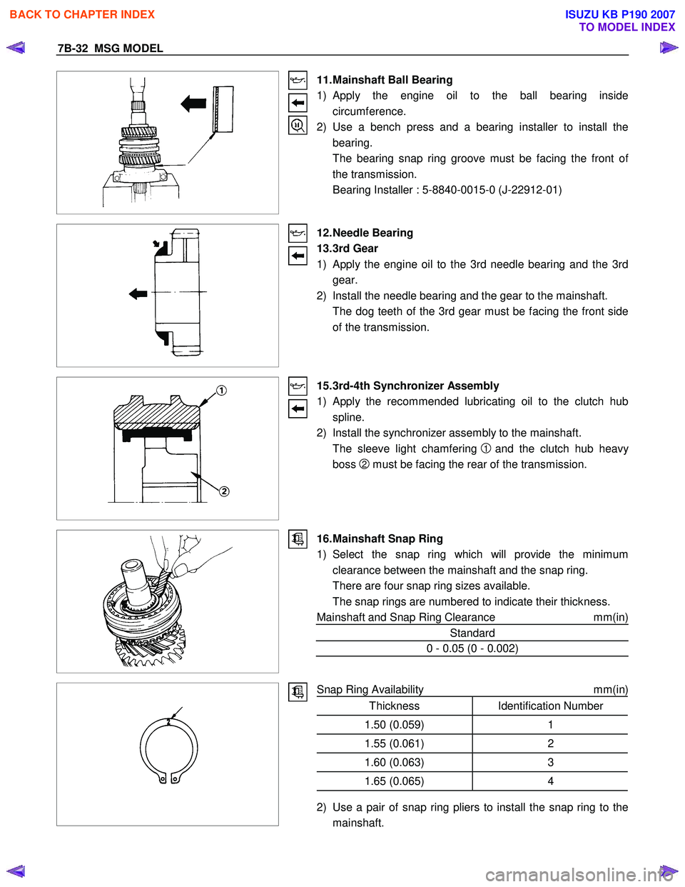
11. Mainshaft Ball Bearing
1) Apply the engine oil to the ball bearing inside circumference.
2) Use a bench press and a bearing installer to install the bearing.
The bearing snap ring groove must be facing the front o
f
the transmission.
Bearing Installer : 5-8840-0015-0 (J-22912-01)
12. Needle Bearing
13. 3rd Gear
1) Apply the engine oil to the 3rd needle bearing and the 3rd
gear.
2) Install the needle bearing and the gear to the mainshaft.
The dog teeth of the 3rd gear must be facing the front side of the transmission.
15. 3rd-4th Synchronizer Assembly
1)
Apply the recommended lubricating oil to the clutch hub
spline.
2) Install the synchronizer assembly to the mainshaft.
The sleeve light chamfering
1 and the clutch hub heavy
boss
2 must be facing the rear of the transmission.
16. Mainshaft Snap Ring
1) Select the snap ring which will provide the minimum clearance between the mainshaft and the snap ring.
There are four snap ring sizes available.
The snap rings are numbered to indicate their thickness.
Mainshaft and Snap Ring Clearance mm(in)
Standard
0 - 0.05 (0 - 0.002)
Snap Ring Availability
mm(in)
Thickness Identification Number
1.50 (0.059) 1
1.55 (0.061)2
1.60 (0.063)3
1.65 (0.065)4
2) Use a pair of snap ring pliers to install the snap ring to the
mainshaft.
BACK TO CHAPTER INDEX
TO MODEL INDEX
ISUZU KB P190 2007
Page 4605 of 6020
MSG MODEL 7B-41
RTW 47BSH000201
Important Operations
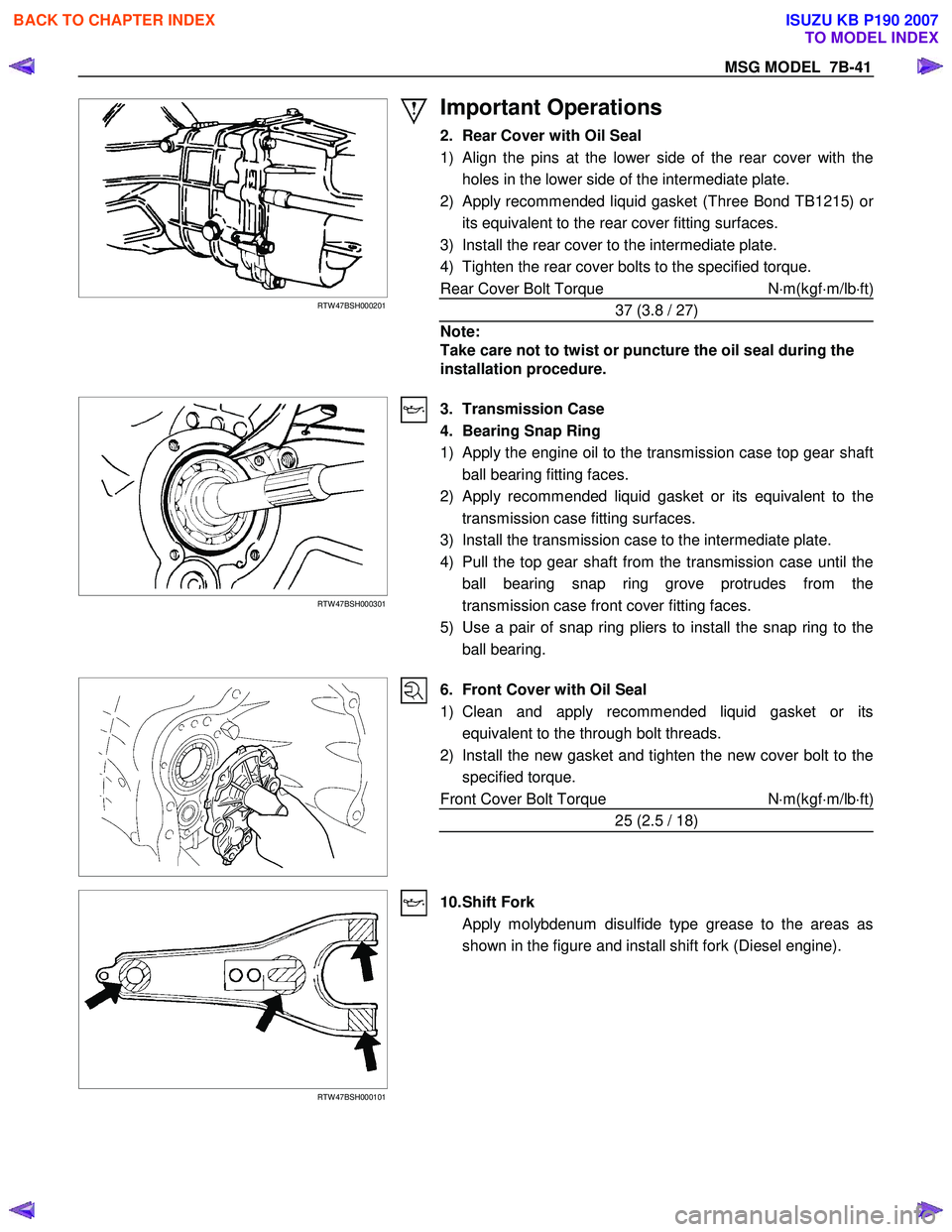
2. Rear Cover with Oil Seal
1)
Align the pins at the lower side of the rear cover with the
holes in the lower side of the intermediate plate.
2) Apply recommended liquid gasket (Three Bond TB1215) o
r
its equivalent to the rear cover fitting surfaces.
3) Install the rear cover to the intermediate plate.
4) Tighten the rear cover bolts to the specified torque.
Rear Cover Bolt Torque N⋅m(kgf ⋅m/lb ⋅ft)
37 (3.8 / 27)
Note:
Take care not to twist or puncture the oil seal during the
installation procedure.
RTW 47BSH000301
3. Transmission Case
4. Bearing Snap Ring
1) Apply the engine oil to the transmission case top gear shaft ball bearing fitting faces.
2)
Apply recommended liquid gasket or its equivalent to the
transmission case fitting surfaces.
3) Install the transmission case to the intermediate plate.
4) Pull the top gear shaft from the transmission case until the ball bearing snap ring grove protrudes from the
transmission case front cover fitting faces.
5) Use a pair of snap ring pliers to install the snap ring to the ball bearing.
6. Front Cover with Oil Seal
1) Clean and apply recommended liquid gasket or its equivalent to the through bolt threads.
2) Install the new gasket and tighten the new cover bolt to the specified torque.
Front Cover Bolt Torque N⋅m(kgf ⋅m/lb ⋅ft)
25 (2.5 / 18)
RTW 47BSH000101
10. Shift Fork
Apply molybdenum disulfide type grease to the areas as shown in the figure and install shift fork (Diesel engine).
BACK TO CHAPTER INDEX
TO MODEL INDEX
ISUZU KB P190 2007
Page 4623 of 6020
MANUAL TRANSMISSION 7B1-17
Disassembly
1. Clean the exterior of the unit with solvent.
2. Remove the drain plug from the transmission case and drain the lubricant.
3. Remove the clutch release bearing with spring from the transmission case.
4. Remove the shift fork, and boot.
5. Remove the front cover and gasket from the transmission case.
6. Remove the snap ring fixing counter front bearing.
7. Use a pair of snap ring pliers to remove the snap ring fixing top gear bearing.
226RS001
8. Remove the speedometer sensor.
Remove the plate.
Remove the driven gear bushing and driven gear.
NOTE: Apply a reference mark to the driven gea
r
bushing before removal.
9. Remove the gear control box assembly.
10. Remove the rear cover assembly from the transmission case and intermediate plate.
11. Remove the intermediate plate with gear assembly from the transmission case.
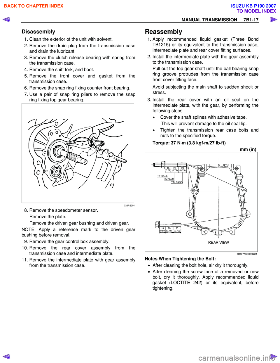
Reassembly
1. Apply recommended liquid gasket (Three Bond
TB1215) or its equivalent to the transmission case,
intermediate plate and rear cover fitting surfaces.
2. Install the intermediate plate with the gear assembly to the transmission case.
Pull out the top gear shaft until the ball bearing snap
ring groove protrudes from the transmission case
front cover fitting face.
Avoid subjecting the main shaft to sudden shock o
r
stress.
3. Install the rear cover with an oil seal on the intermediate plate, with the gear, by performing the
following steps.
• Cover the shaft splines with adhesive tape.
This will prevent damage to the oil seal lip. • Tighten the transmission rear case bolts and
nuts to the specified torque.
Torque: 37 N ⋅
⋅⋅
⋅
m (3.8 kgf ⋅
⋅⋅
⋅
m/27 lb ⋅
⋅⋅
⋅
ft)
mm (in)
RTW 77BSH008601
Notes When Tightening the Bolt:
• After cleaning the bolt hole, air dry it thoroughly.
• After cleaning the screw face of a removed or ne
w
bolt, dry it thoroughly.
Apply recommended liquid
gasket (LOCTITE 242) or its equivalent, before
tightening.
BACK TO CHAPTER INDEX
TO MODEL INDEX
ISUZU KB P190 2007
Page 4624 of 6020
7B1-18 MANUAL TRANSMISSION
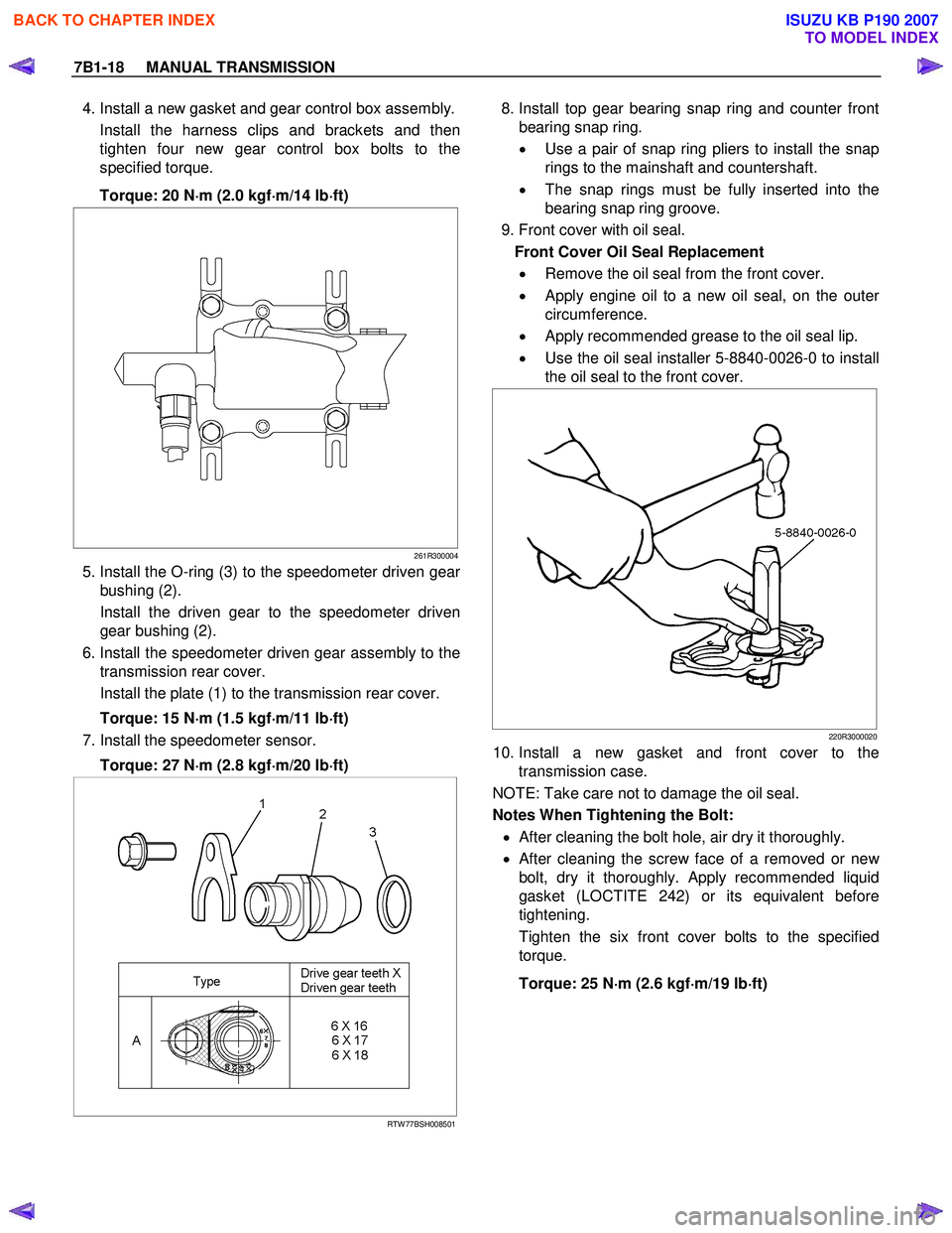
4. Install a new gasket and gear control box assembly.
Install the harness clips and brackets and then
tighten four new gear control box bolts to the
specified torque.
Torque: 20 N ⋅
⋅⋅
⋅
m (2.0 kgf ⋅
⋅⋅
⋅
m/14 lb ⋅
⋅⋅
⋅
ft)
261R300004
5. Install the O-ring (3) to the speedometer driven gear
bushing (2).
Install the driven gear to the speedometer driven gear bushing (2).
6. Install the speedometer driven gear assembly to the transmission rear cover.
Install the plate (1) to the transmission rear cover.
Torque: 15 N ⋅
⋅⋅
⋅
m (1.5 kgf ⋅
⋅⋅
⋅
m/11 lb ⋅
⋅⋅
⋅
ft)
7. Install the speedometer sensor.
Torque: 27 N ⋅
⋅⋅
⋅
m (2.8 kgf ⋅
⋅⋅
⋅
m/20 lb ⋅
⋅⋅
⋅
ft)
RTW 77BSH008501
8. Install top gear bearing snap ring and counter front
bearing snap ring.
• Use a pair of snap ring pliers to install the snap
rings to the mainshaft and countershaft.
• The snap rings must be fully inserted into the
bearing snap ring groove.
9. Front cover with oil seal. Front Cover Oil Seal Replacement • Remove the oil seal from the front cover.
• Apply engine oil to a new oil seal, on the oute
r
circumference.
• Apply recommended grease to the oil seal lip.
• Use the oil seal installer 5-8840-0026-0 to install
the oil seal to the front cover.
220R3000020
10. Install a new gasket and front cover to the transmission case.
NOTE: Take care not to damage the oil seal.
Notes When Tightening the Bolt:
• After cleaning the bolt hole, air dry it thoroughly.
•
After cleaning the screw face of a removed or new
bolt, dry it thoroughly. Apply recommended liquid
gasket (LOCTITE 242) or its equivalent before
tightening.
Tighten the six front cover bolts to the specified
torque.
Torque: 25 N ⋅
⋅⋅
⋅
m (2.6 kgf ⋅
⋅⋅
⋅
m/19 lb ⋅
⋅⋅
⋅
ft)
BACK TO CHAPTER INDEX
TO MODEL INDEX
ISUZU KB P190 2007
Page 4678 of 6020
7B1-72 MANUAL TRANSMISSION
Disassembly
1. Clean the exterior of the unit with solvent.
2. Remove the drain plug from the transmission case and drain the lubricant.
3. Remove the clutch release bearing with spring from the transmission case.
4. Remove the shift fork, and boot.
5. Remove the front cover and gasket from the transmission case.
6. Remove the snap ring fixing counter front bearing.
7. Use a pair of snap ring pliers to remove the snap ring fixing top gear bearing.
226RS001
8. Remove the gear control box assembly.
9. Remove the rear case assembly from the transmission case and intermediate plate.
10. Remove the intermediate plate with gear assembl
y
from the transmission case.
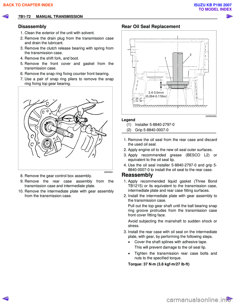
Rear Oil Seal Replacement
220R300025
Legend
(1) Installer 5-8840-2797-0
(2) Grip 5-8840-0007-0
1. Remove the oil seal from the rear case and discard the used oil seal.
2. Apply engine oil to the new oil seal outer surfaces.
3.
Apply recommended grease (BESCO L2) or
equivalent to the oil seal lip.
4. Use the oil seal installer 5-8840-2797-0 and grip 5- 8840-0007-0 to install the oil seal to the rear case.
Reassembly
1. Apply recommended liquid gasket (Three Bond TB1215) or its equivalent to the transmission case,
intermediate plate and rear case fitting surfaces.
2. Install the intermediate plate with gear assembly to the transmission case.
Pull out the top gear shaft until the ball bearing snap
ring groove protrudes from the transmission case
front cover fitting face.
Avoid subjecting the mainshaft to sudden shock or
stress.
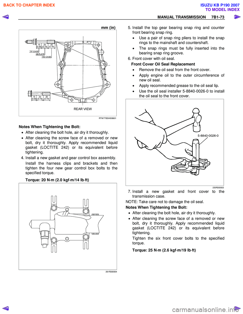
3. Install the rear case with oil seal on the intermediate plate, with gear, by performing the following steps.
• Cover the shaft splines with adhesive tape.
This will prevent damage to the oil seal lip.
• Tighten the transmission rear case bolts and
nuts to the specified torque.
Torque: 37 N ⋅
⋅⋅
⋅
m (3.8 kgf ⋅
⋅⋅
⋅
m/27 lb ⋅
⋅⋅
⋅
ft)
BACK TO CHAPTER INDEX
TO MODEL INDEX
ISUZU KB P190 2007
Page 4679 of 6020
MANUAL TRANSMISSION 7B1-73
mm (in)
RTW 77BSH008601
Notes When Tightening the Bolt:
• After cleaning the bolt hole, air dry it thoroughly.
•
After cleaning the screw face of a removed or new
bolt, dry it thoroughly. Apply recommended liquid
gasket (LOCTITE 242) or its equivalent before
tightening.
4. Install a new gasket and gear control box assembly. Install the harness clips and brackets and then
tighten the four new gear control box bolts to the
specified torque.
Torque: 20 N ⋅
⋅⋅
⋅
m (2.0 kgf ⋅
⋅⋅
⋅
m/14 lb ⋅
⋅⋅
⋅
ft)
261R300004
5. Install the top gear bearing snap ring and counte
r
front bearing snap ring.
• Use a pair of snap ring pliers to install the snap
rings to the mainshaft and countershaft.
• The snap rings must be fully inserted into the
bearing snap ring groove.
6. Front cover with oil seal. Front Cover Oil Seal Replacement • Remove the oil seal from the front cover.
• Apply engine oil to the outer circumference o
f
new oil seal.
• Apply recommended grease to the oil seal lip.
• Use the oil seal installer 5-8840-0026-0 to install
the oil seal to the front cover.
220R300002
7. Install a new gasket and front cover to the transmission case.
NOTE: Take care not to damage the oil seal.
Notes When Tightening the Bolt:
• After cleaning the bolt hole, air dry it thoroughly.
•
After cleaning the screw face of a removed or new
bolt, dry it thoroughly.
Apply recommended liquid
gasket (LOCTITE 242) or its equivalent before
tightening.
Tighten the six front cover bolts to the specified
torque.
Torque: 25 N ⋅
⋅⋅
⋅
m (2.6 kgf ⋅
⋅⋅
⋅
m/19 lb ⋅
⋅⋅
⋅
ft)
BACK TO CHAPTER INDEX
TO MODEL INDEX
ISUZU KB P190 2007
Page 4748 of 6020
Manual Transmission (MUX) 7B1-29
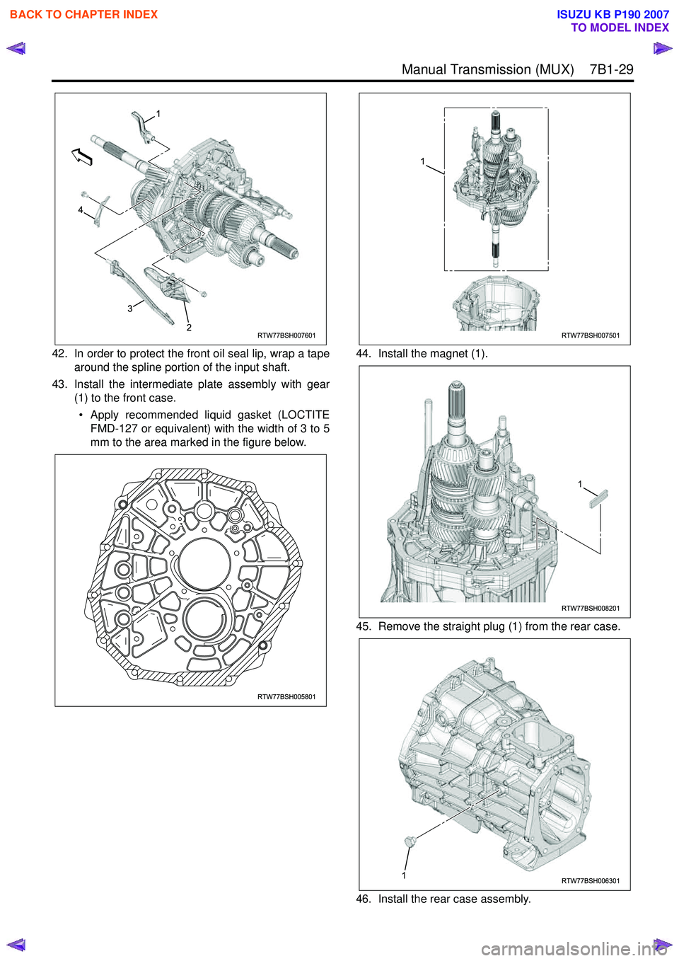
42. In order to protect the front oil seal lip, wrap a tapearound the spline portion of the input shaft.
43. Install the intermediate plate assembly with gear (1) to the front case.
• Apply recommended liquid gasket (LOCTITE FMD-127 or equivalent) with the width of 3 to 5
mm to the area marked in the figure below. 44. Install the magnet (1).
45. Remove the straight plug (1) from the rear case.
46. Install the rear case assembly.
RTW77BSH007601
1
4
3
2
RTW77BSH005801
RTW77BSH007501
1
RTW77BSH008201
1
RTW77BSH0063011
BACK TO CHAPTER INDEX
TO MODEL INDEX
ISUZU KB P190 2007