2007 ISUZU KB P190 recommended oil
[x] Cancel search: recommended oilPage 3753 of 6020
Exhaust System – V6 Page 6F – 5
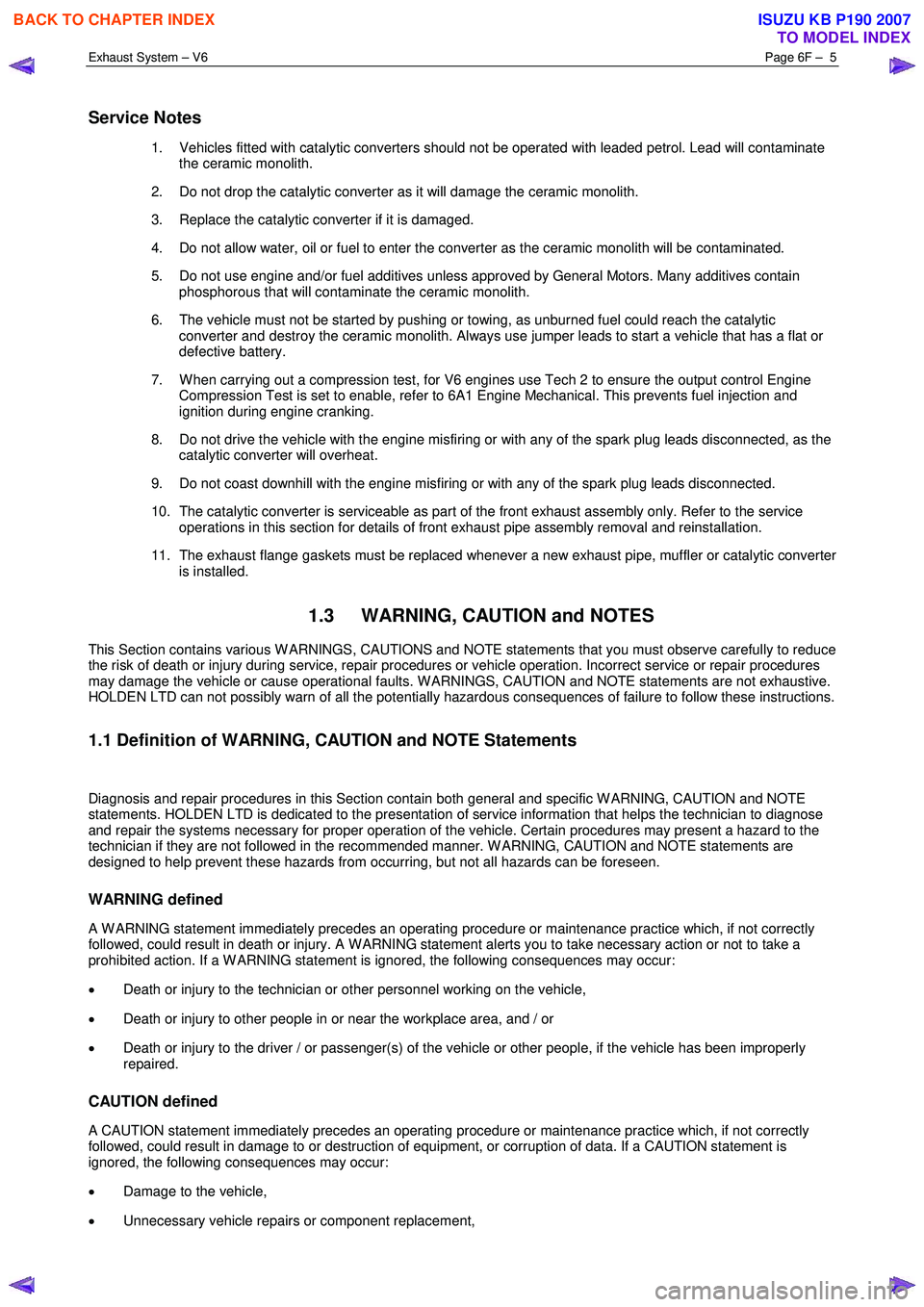
Service Notes
1. Vehicles fitted with catalytic converters should not be operated with leaded petrol. Lead will contaminate
the ceramic monolith.
2. Do not drop the catalytic converter as it will damage the ceramic monolith.
3. Replace the catalytic converter if it is damaged.
4. Do not allow water, oil or fuel to enter the converter as the ceramic monolith will be contaminated.
5. Do not use engine and/or fuel additives unless approved by General Motors. Many additives contain phosphorous that will contaminate the ceramic monolith.
6. The vehicle must not be started by pushing or towing, as unburned fuel could reach the catalytic converter and destroy the ceramic monolith. Always use jumper leads to start a vehicle that has a flat or
defective battery.
7. W hen carrying out a compression test, for V6 engines use Tech 2 to ensure the output control Engine Compression Test is set to enable, refer to 6A1 Engine Mechanical. This prevents fuel injection and
ignition during engine cranking.
8. Do not drive the vehicle with the engine misfiring or with any of the spark plug leads disconnected, as the catalytic converter will overheat.
9. Do not coast downhill with the engine misfiring or with any of the spark plug leads disconnected.
10. The catalytic converter is serviceable as part of the front exhaust assembly only. Refer to the service operations in this section for details of front exhaust pipe assembly removal and reinstallation.
11. The exhaust flange gaskets must be replaced whenever a new exhaust pipe, muffler or catalytic converter is installed.
1.3 WARNING, CAUTION and NOTES
This Section contains various W ARNINGS, CAUTIONS and NOTE statements that you must observe carefully to reduce
the risk of death or injury during service, repair procedures or vehicle operation. Incorrect service or repair procedures
may damage the vehicle or cause operational faults. W ARNINGS, CAUTION and NOTE statements are not exhaustive.
HOLDEN LTD can not possibly warn of all the potentially hazardous consequences of failure to follow these instructions.
1.1 Definition of WARNING, CAUTION and NOTE Statements
Diagnosis and repair procedures in this Section contain both general and specific W ARNING, CAUTION and NOTE
statements. HOLDEN LTD is dedicated to the presentation of service information that helps the technician to diagnose
and repair the systems necessary for proper operation of the vehicle. Certain procedures may present a hazard to the
technician if they are not followed in the recommended manner. W ARNING, CAUTION and NOTE statements are
designed to help prevent these hazards from occurring, but not all hazards can be foreseen.
WARNING defined
A W ARNING statement immediately precedes an operating procedure or maintenance practice which, if not correctly
followed, could result in death or injury. A W ARNING statement alerts you to take necessary action or not to take a
prohibited action. If a W ARNING statement is ignored, the following consequences may occur:
• Death or injury to the technician or other personnel working on the vehicle,
• Death or injury to other people in or near the workplace area, and / or
• Death or injury to the driver / or passenger(s) of the vehicle or other people, if the vehicle has been improperly
repaired.
CAUTION defined
A CAUTION statement immediately precedes an operating procedure or maintenance practice which, if not correctly
followed, could result in damage to or destruction of equipment, or corruption of data. If a CAUTION statement is
ignored, the following consequences may occur:
• Damage to the vehicle,
• Unnecessary vehicle repairs or component replacement,
BACK TO CHAPTER INDEX
TO MODEL INDEX
ISUZU KB P190 2007
Page 3772 of 6020
Automatic Transmission – 4L60E – General Information Page 7C1–12
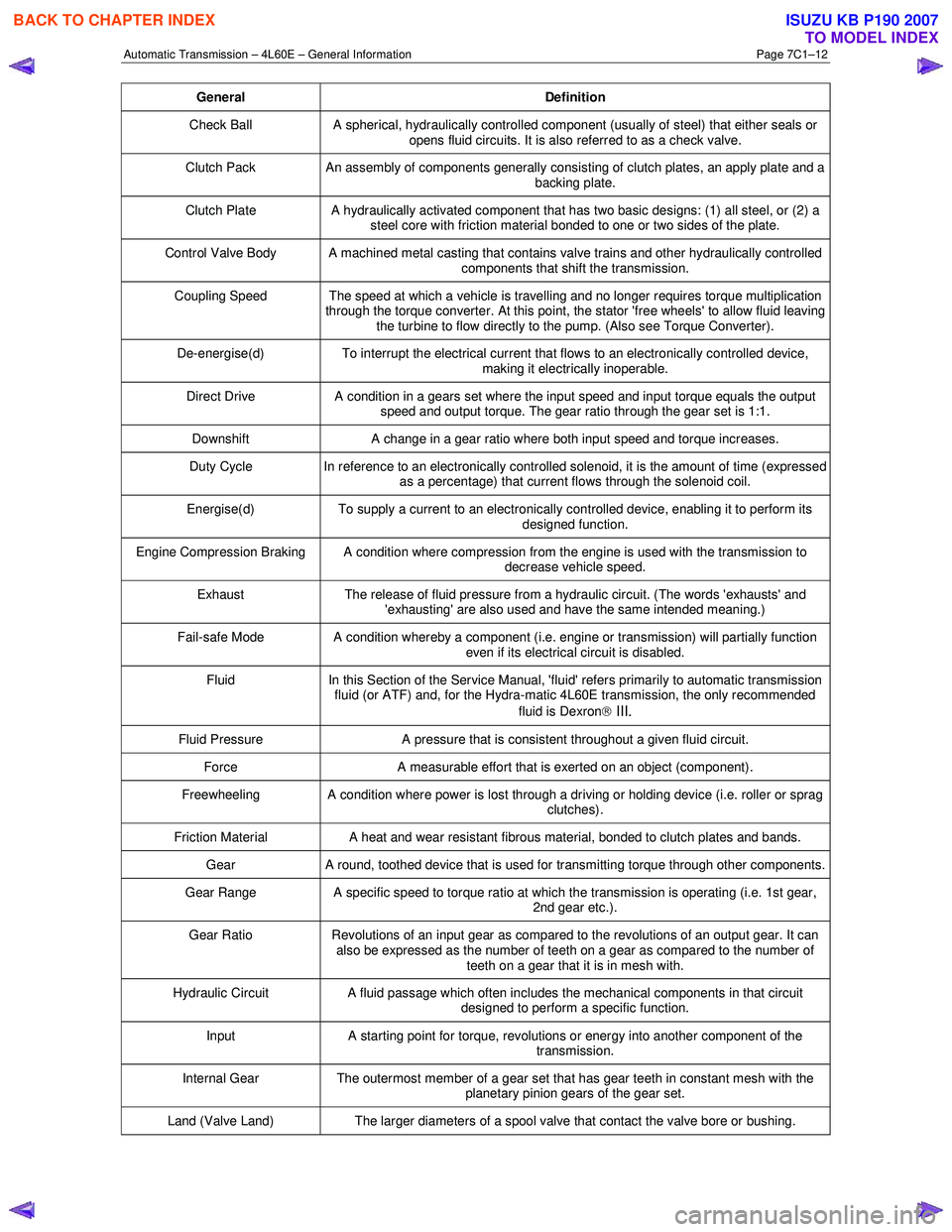
General Definition
Check Ball A spherical, hydraulically controlled component (usually of steel) that either seals or
opens fluid circuits. It is also referred to as a check valve.
Clutch Pack An assembly of components generally consisting of clutch plates, an apply plate and a
backing plate.
Clutch Plate A hydraulically activated component that has two basic designs: (1) all steel, or (2) a
steel core with friction material bonded to one or two sides of the plate.
Control Valve Body A machined metal casting that contains valve trains and other hydraulically controlled components that shift the transmission.
Coupling Speed The speed at which a vehicle is travelling and no longer requires torque multiplication through the torque converter. At this point, the stator 'free wheels' to allow fluid leaving
the turbine to flow directly to the pump. (Also see Torque Converter).
De-energise(d) To interrupt the electrical current that flows to an electronically controlled device,
making it electrically inoperable.
Direct Drive A condition in a gears set where the input speed and input torque equals the output
speed and output torque. The gear ratio through the gear set is 1:1.
Downshift A change in a gear ratio where both input speed and torque increases.
Duty Cycle In reference to an electronically controlled solenoid, it is the amount of time (expressed
as a percentage) that current flows through the solenoid coil.
Energise(d) To supply a current to an electronically controlled device, enabling it to perform its
designed function.
Engine Compression Braking A condition where compression from the engine is used with the transmission to decrease vehicle speed.
Exhaust The release of fluid pressure from a hydraulic circuit. (The words 'exhausts' and
'exhausting' are also used and have the same intended meaning.)
Fail-safe Mode A condition whereby a component (i.e. engine or transmission) will partially function even if its electrical circuit is disabled.
Fluid In this Section of the Service Manual, 'fluid' refers primarily to automatic transmission
fluid (or ATF) and, for the Hydra-matic 4L60E transmission, the only recommended
fluid is Dexron
III.
Fluid Pressure A pressure that is consistent throughout a given fluid circuit.
Force A measurable effort that is exerted on an object (component).
Freewheeling A condition where power is lost through a driving or holding device (i.e. roller or sprag
clutches).
Friction Material A heat and wear resistant fibrous material, bonded to clutch plates and bands.
Gear A round, toothed device that is used for transmitting torque through other components.
Gear Range A specific speed to torque ratio at which the transmission is operating (i.e. 1st gear,
2nd gear etc.).
Gear Ratio Revolutions of an input gear as compared to the revolutions of an output gear. It can
also be expressed as the number of teeth on a gear as compared to the number of
teeth on a gear that it is in mesh with.
Hydraulic Circuit A fluid passage which often includes the mechanical components in that circuit
designed to perform a specific function.
Input A starting point for torque, revolutions or energy into another component of the
transmission.
Internal Gear The outermost member of a gear set that has gear teeth in constant mesh with the
planetary pinion gears of the gear set.
Land (Valve Land) The larger diameters of a spool valve that contact the valve bore or bushing.
BACK TO CHAPTER INDEX
TO MODEL INDEX
ISUZU KB P190 2007
Page 3777 of 6020
Automatic Transmission – 4L60E – General Information Page 7C1–17
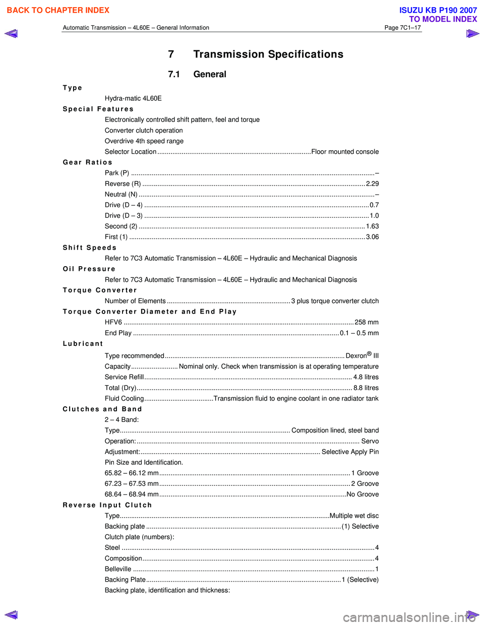
7 Transmission Specifications
7.1 General
Type
Hydra-matic 4L60E
Special Features
Electronically controlled shift pattern, feel and torque
Converter clutch operation
Overdrive 4th speed range
Selector Location ..................................................................................Floor mounted console
Gear Ratios Park (P) ....................................................................................................................... ........... –
Reverse (R) .................................................................................................................... ... 2.29
Neutral (N) .............................................................................................................................. –
Drive (D – 4) .................................................................................................................. ...... 0.7
Drive (D – 3) .................................................................................................................. ...... 1.0
Second (2) ......................................................................................................................... 1.63
First (1) ...................................................................................................................... ........ 3.06
Shift Speeds Refer to 7C3 Automatic Transmission – 4L60E – Hydraulic and Mechanical Diagnosis
Oil Pressure
Refer to 7C3 Automatic Transmission – 4L60E – Hydraulic and Mechanical Diagnosis
Torque Converter
Number of Elements .................................................................. 3 plus torque converter clutch
Torque Converter Diameter and End Play
HFV6 ........................................................................................................................... 258 mm
End Play .............................................................................................................. 0.1 – 0.5 mm
Lubricant
Type recommended ................................................................................................ Dexron
® III
Capacity......................... Nominal only. Check when transmission is at operating temperature
Service Refill ............................................................................................................... 4. 8 litres
Total (Dry)................................................................................................................... 8 .8 litres
Fluid Cooling.....................................Transmission fluid to engine coolant in one radiator tank
Clutches and Band 2 – 4 Band:
Type........................................................................................... Composition lined, steel band
Operation: ..................................................................................................................... .. Servo
Adjustment: ................................................................................................ Selective Apply Pin
Pin Size and Identification.
65.82 – 66.12 mm ...................................................................................................... 1 Groove
67.23 – 67.53 mm ...................................................................................................... 2 Groove
68.64 – 68.94 mm ....................................................................................................No Groove
Reverse Input Clutch Type................................................................................................................Multiple we t disc
Backing plate ........................................................................................................ (1) Select ive
Clutch plate (numbers):
Steel ....................................................................................................................................... 4
Composition............................................................................................................................ 4
Belleville ..................................................................................................................... ............ 1
Backing Plate ........................................................................................................ 1 (Selecti ve)
Backing plate, identification and thickness:
BACK TO CHAPTER INDEX
TO MODEL INDEX
ISUZU KB P190 2007
Page 3918 of 6020
Automatic Transmission – 4L60E – On-vehicle Servicing Page 7C4–5
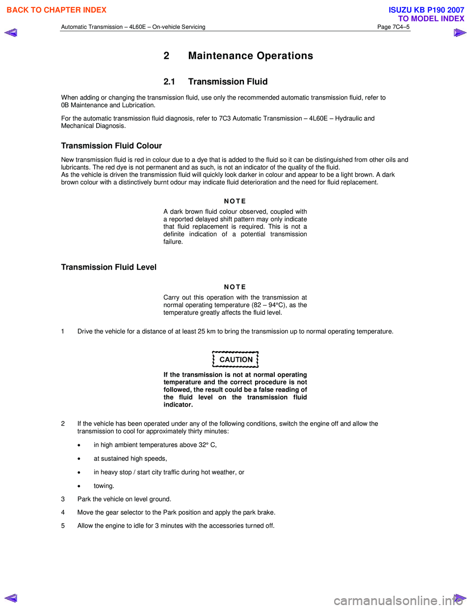
2 Maintenance Operations
2.1 Transmission Fluid
When adding or changing the transmission fluid, use only the recommended automatic transmission fluid, refer to
0B Maintenance and Lubrication.
For the automatic transmission fluid diagnosis, refer to 7C3 Automatic Transmission – 4L60E – Hydraulic and
Mechanical Diagnosis.
Transmission Fluid Colour
New transmission fluid is red in colour due to a dye that is added to the fluid so it can be distinguished from other oils and
lubricants. The red dye is not permanent and as such, is not an indicator of the quality of the fluid.
As the vehicle is driven the transmission fluid will quickly look darker in colour and appear to be a light brown. A dark
brown colour with a distinctively burnt odour may indicate fluid deterioration and the need for fluid replacement.
NOTE
A dark brown fluid colour observed, coupled with
a reported delayed shift pattern may only indicate
that fluid replacement is required. This is not a
definite indication of a potential transmission
failure.
Transmission Fluid Level
NOTE
Carry out this operation with the transmission at
normal operating temperature (82 – 94°C), as the
temperature greatly affects the fluid level.
1 Drive the vehicle for a distance of at least 25 km to bring the transmission up to normal operating temperature.
If the transmission is not at normal operating
temperature and the correct procedure is not
followed, the result could be a false reading of
the fluid level on the transmission fluid
indicator.
2 If the vehicle has been operated under any of the following conditions, switch the engine off and allow the transmission to cool for approximately thirty minutes:
• in high ambient temperatures above 32° C,
• at sustained high speeds,
• in heavy stop / start city traffic during hot weather, or
• towing.
3 Park the vehicle on level ground.
4 Move the gear selector to the Park position and apply the park brake.
5 Allow the engine to idle for 3 minutes with the accessories turned off.
BACK TO CHAPTER INDEX
TO MODEL INDEX
ISUZU KB P190 2007
Page 3919 of 6020

Automatic Transmission – 4L60E – On-vehicle Servicing Page 7C4–6
6 Lift the locking lever (1) on the transmission fluid
indicator, then remove the indicator from the filler
tube (2) and check the fluid colour, condition and level.
Do not overfill the transmission. Overfilling
can cause aeration resulting in fluid loss,
shift complaints and possible damage to the
transmission.
7 If the transmission fluid level is low, add only enough of the recommended fluid until
its level shows onto the
crosshatch hot area (3) of the fluid indicator.
Figure 7C4 – 1
2.2 Reverse Flush and Flow Rate Test
It is essential to perform a reverse flush and oil cooler flow rate test after any of the following:
• the transmission is repaired or replaced,
• fluid contamination is suspected, or
• whenever the oil pump and/or torque converter is replaced.
NOTE
The reverse flush must be completed prior to
conducting a flow rate test.
Reverse Flush
1 Disconnect both cooler hose/line assemblies at the transmission and at the radiator cooler, refer to 3.17 Transmission Cooler Line/Hose Assemblies.
2 Check the cooler hose/line to radiator cooler fittings for damage, replace as required.
To avoid personal injury, wear safety glasses
when using compressed air.
3 Carefully check the radiator cooler lower fitting to see if any foreign material is evident at this point. If foreign material is found, remove it with a suitable tool and/or compressed air at a reduced pressure of approximately
345 kPa blown in the reverse direction through the cooler.
4 Using compressed air at a reduced pressure of approximately 345 kPa blown in a reverse direction, clean the cooler hose/line assemblies.
5 Reconnect the cooler outlet line to the transmission and both cooler hose/line assemblies to the radiator cooler fittings, refer to 3.17 Transmission Cooler Line/Hose Assemblies.
NOTE
Do not reconnect the cooler inlet line at the
transmission end. This line needs to be left
disconnected to perform the flow rate test.
6 Perform the flow rate test, refer to Flow Rate Test in this Section.
BACK TO CHAPTER INDEX
TO MODEL INDEX
ISUZU KB P190 2007
Page 3942 of 6020
Automatic Transmission – 4L60E – On-vehicle Servicing Page 7C4–29
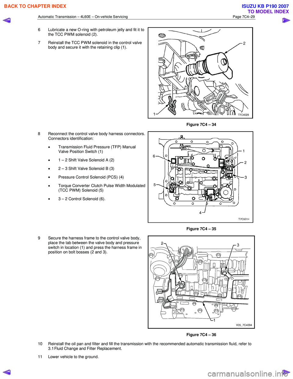
6 Lubricate a new O-ring with petroleum jelly and fit it to
the TCC PW M solenoid (2).
7 Reinstall the TCC PWM solenoid in the control valve body and secure it with the retaining clip (1).
Figure 7C4 – 34
8 Reconnect the control valve body harness connectors. Connectors identification:
• Transmission Fluid Pressure (TFP) Manual
Valve Position Switch (1)
• 1 – 2 Shift Valve Solenoid A (2)
• 2 – 3 Shift Valve Solenoid B (3)
• Pressure Control Solenoid (PCS) (4)
• Torque Converter Clutch Pulse W idth Modulated
(TCC PWM) Solenoid (5)
• 3 – 2 Control Solenoid (6).
Figure 7C4 – 35
9 Secure the harness frame to the control valve body, place the tab between the valve body and pressure
switch in location (1) and press the harness frame in
position on bolt bosses (2 and 3).
Figure 7C4 – 36
10 Reinstall the oil pan and filter and fill the transmission with the recommended automatic transmission fluid, refer to 3.1 Fluid Change and Filter Replacement.
11 Lower vehicle to the ground.
BACK TO CHAPTER INDEX
TO MODEL INDEX
ISUZU KB P190 2007
Page 3952 of 6020
Automatic Transmission – 4L60E – On-vehicle Servicing Page 7C4–39
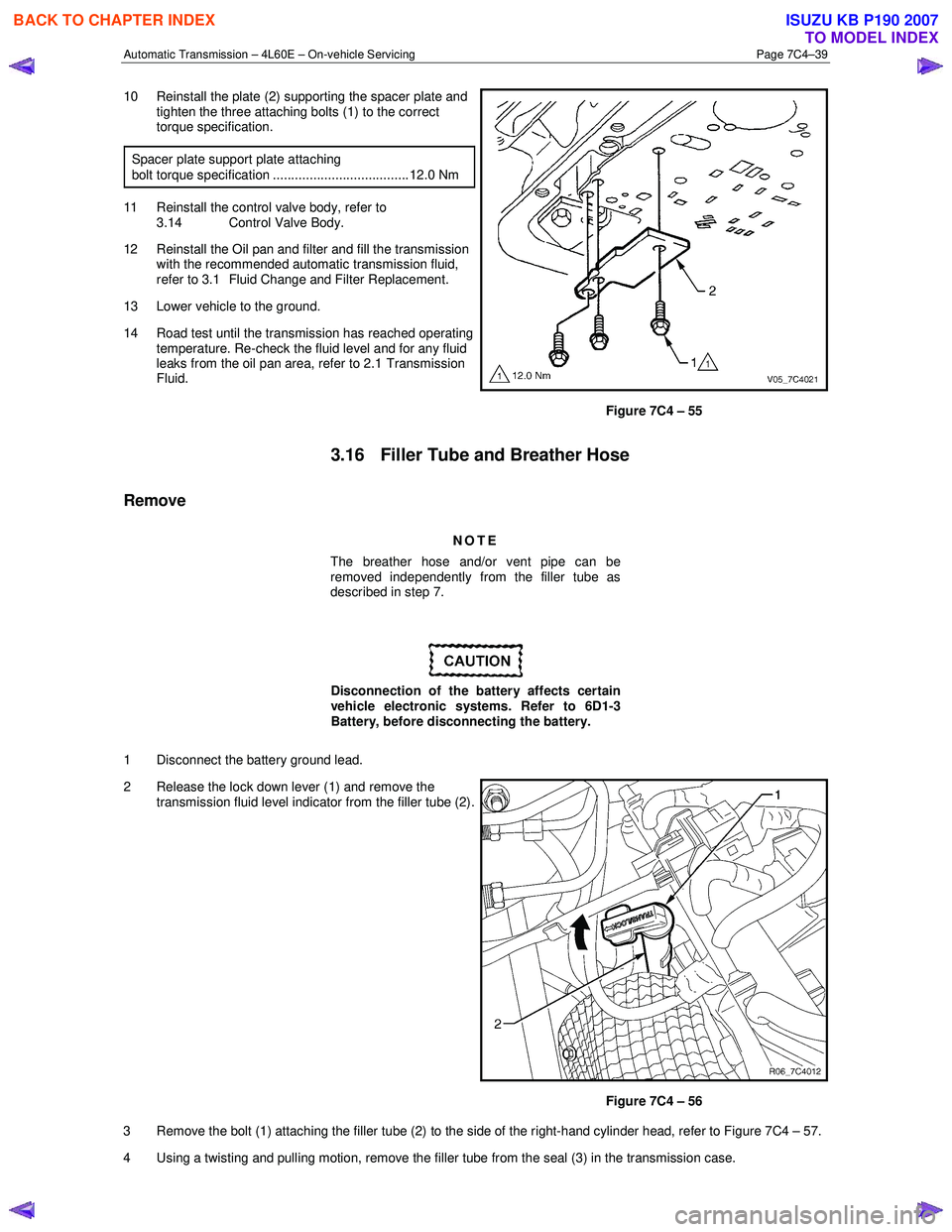
10 Reinstall the plate (2) supporting the spacer plate and
tighten the three attaching bolts (1) to the correct
torque specification.
Spacer plate support plate attaching
bolt torque specification ..................................... 12.0 Nm
11 Reinstall the control valve body, refer to 3.14 Control Valve Body.
12 Reinstall the Oil pan and filter and fill the transmission with the recommended automatic transmission fluid,
refer to 3.1 Fluid Change and Filter Replacement.
13 Lower vehicle to the ground.
14 Road test until the transmission has reached operating temperature. Re-check the fluid level and for any fluid
leaks from the oil pan area, refer to 2.1 Transmission
Fluid.
Figure 7C4 – 55
3.16 Filler Tube and Breather Hose
Remove
NOTE
The breather hose and/or vent pipe can be
removed independently from the filler tube as
described in step 7.
Disconnection of the battery affects certain
vehicle electronic systems. Refer to 6D1-3
Battery, before disconnecting the battery.
1 Disconnect the battery ground lead.
2 Release the lock down lever (1) and remove the transmission fluid level indicator from the filler tube (2).
Figure 7C4 – 56
3 Remove the bolt (1) attaching the filler tube (2) to the side of the right-hand cylinder head, refer to Figure 7C4 – 57.
4 Using a twisting and pulling motion, remove the filler tube from the seal (3) in the transmission case.
BACK TO CHAPTER INDEX
TO MODEL INDEX
ISUZU KB P190 2007
Page 4171 of 6020
7A4–36 UNIT REPAIR (AW30–40LE)
Diaassembly, Inspection and
Reassembly of minor Components
NOTE: The instructions here are organized so that you
work on only one component group at a time.
This will help avoid confusion from similar-looking parts
of different subassemblies being on your workbench at
the same time.
The component groups are inspected and repaired from
the converter housing side.
As much as possible, complete the inspection, repair
and reassembly before proceeding to the next
component group. If a component group cannot be
reassembled because parts are being ordered, be sure
to keep all parts of that group in separate container
while proceeding with disassembly, inspection, repair
and reassembly of other component groups.
Recommended ATF type DEXRON III.
General Cleaning Notes:
1. All disassembled parts should be washed clean and any fluid passages and holes should be blown
through with compressed air.
2. When using compressed air to dry parts, always aim away from yourself to prevent accidentally spraying
automatic transmission fluid in your face.
3. The recommended automatic transmission fluid should be used for cleaning.
Parts Arrangement:
1. After cleaning, the parts should be arranged inproper order to allow performing inspection, repairs,
and reassembly with efficiency.
2. When disassembling a valve body, be sure to keep each valve together with the corresponding spring.
3. New brakes and clutches that are to be used for replacement must be soaked in transmission fluid
for at least thirty minutes before assembly.
General Assembly:
1. All oil seal rings, clutch discs, clutch plates, rotating parts, and sliding surfaces should be coated with
transmission fluid prior to reassembly.
2. All gaskets and rubber O-ring should be replaced.
3. Make sure that the ends of a snap ring are not aligned with one of the cutouts and are installed in
the groove correctly.
4. If a worn bushing is to be replaced, the subassembly containing that bushing must be
replaced.
5. Check thrust bearings and races for wear or damage. Replace if necessary.
6. Use petroleum jelly or vaseline to keep parts in place.
BACK TO CHAPTER INDEX
TO MODEL INDEX
ISUZU KB P190 2007