2007 ISUZU KB P190 recommended oil
[x] Cancel search: recommended oilPage 2073 of 6020
ENGINE MECHANICAL (C24SE) 6A-59
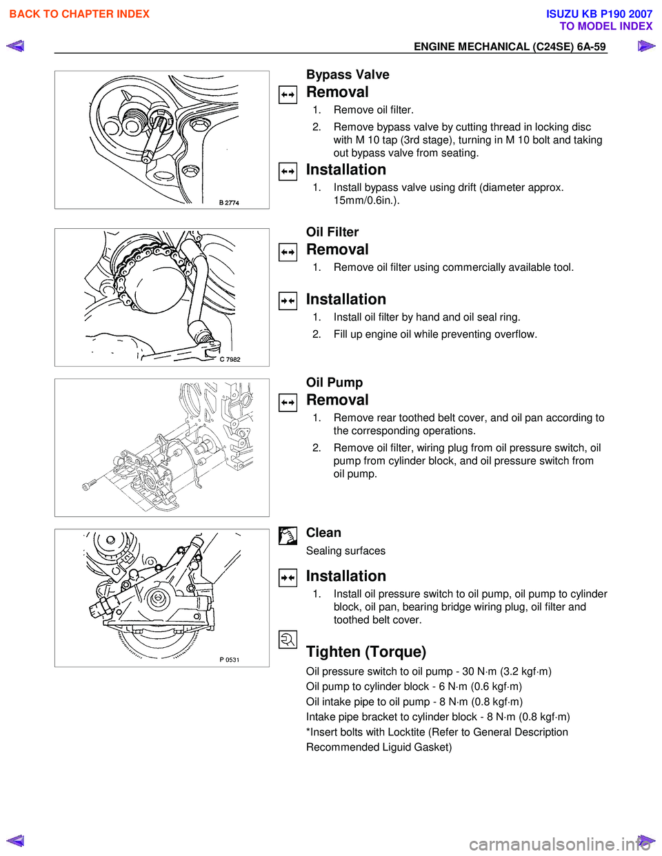
Bypass Valve
Removal
1. Remove oil filter.
2. Remove bypass valve by cutting thread in locking disc with M 10 tap (3rd stage), turning in M 10 bolt and taking
out bypass valve from seating.
Installation
1. Install bypass valve using drift (diameter approx. 15mm/0.6in.).
Oil Filter
Removal
1. Remove oil filter using commercially available tool.
Installation
1. Install oil filter by hand and oil seal ring.
2. Fill up engine oil while preventing overflow.
Oil Pump
Removal
1. Remove rear toothed belt cover, and oil pan according to the corresponding operations.
2. Remove oil filter, wiring plug from oil pressure switch, oil pump from cylinder block, and oil pressure switch from
oil pump.
Clean
Sealing surfaces
Installation
1. Install oil pressure switch to oil pump, oil pump to cylinder
block, oil pan, bearing bridge wiring plug, oil filter and
toothed belt cover.
Tighten (Torque)
Oil pressure switch to oil pump - 30 N ⋅m (3.2 kgf ⋅m)
Oil pump to cylinder block - 6 N ⋅m (0.6 kgf ⋅m)
Oil intake pipe to oil pump - 8 N ⋅m (0.8 kgf ⋅m)
Intake pipe bracket to cylinder block - 8 N ⋅m (0.8 kgf ⋅m)
*Insert bolts with Locktite (Refer to General Description
Recommended Liguid Gasket)
BACK TO CHAPTER INDEX
TO MODEL INDEX
ISUZU KB P190 2007
Page 2102 of 6020
6A-88 ENGINE MECHANICAL (C24SE)
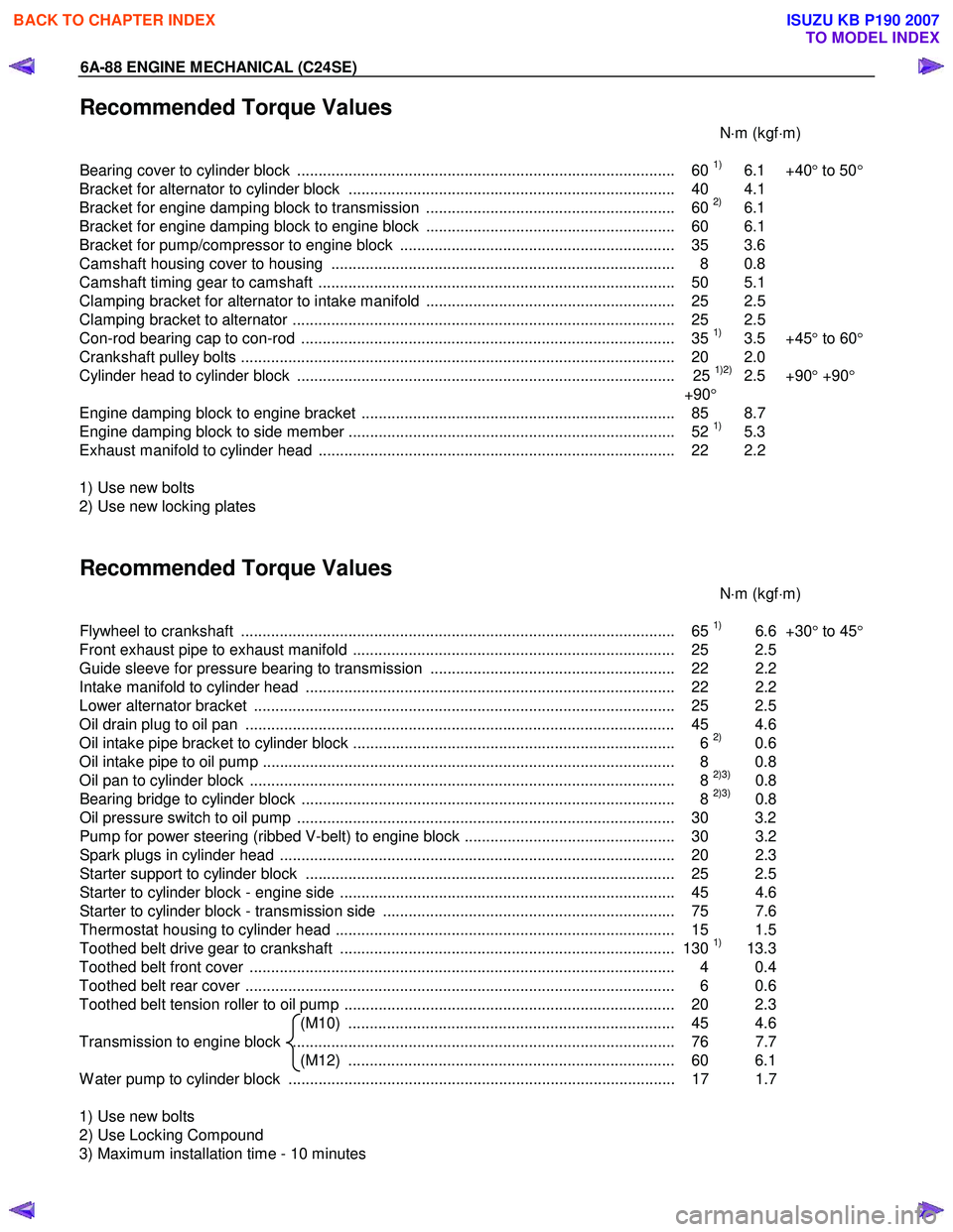
Recommended Torque Values
N⋅m (kgf ⋅m)
Bearing cover to cylinder block ........................................................................................ 60
1) 6.1 +40 ° to 50 °
Bracket for alternator to cylinder block ............................................................................ 40 4.1
Bracket for engine damping block to transmission .......................................................... 60
2) 6.1
Bracket for engine damping block to engine block .......................................................... 60 6.1
Bracket for pump/compressor to engine block ................................................................ 35 3.6
Camshaft housing cover to housing ................................................................................ 8 0.8
Camshaft timing gear to camshaft ................................................................................... 50 5.1
Clamping bracket for alternator to intake manifold .......................................................... 25 2.5
Clamping bracket to alternator ......................................................................................... 25 2.5
Con-rod bearing cap to con-rod ....................................................................................... 35
1) 3.5 +45 ° to 60 °
Crankshaft pulley bolts ..................................................................................................... 2 0 2.0
Cylinder head to cylinder block ........................................................................................ 25
1)2) 2.5 +90 ° +90 °
+90 °
Engine damping block to engine bracket ......................................................................... 85 8.7
Engine damping block to side member ............................................................................ 52
1) 5.3
Exhaust manifold to cylinder head ................................................................................... 22 2.2
1) Use new bolts
2) Use new locking plates
Recommended Torque Values
N⋅m (kgf ⋅m)
Flywheel to crankshaft ..................................................................................................... 65
1) 6.6 +30° to 45 °
Front exhaust pipe to exhaust manifold ........................................................................... 25 2.5
Guide sleeve for pressure bearing to transmission ......................................................... 22 2.2
Intake manifold to cylinder head ...................................................................................... 22 2.2
Lower alternator bracket .................................................................................................. 25 2.5
Oil drain plug to oil pan .................................................................................................... 45 4.6
Oil intake pipe bracket to cylinder block ........................................................................... 6
2) 0.6
Oil intake pipe to oil pump ................................................................................................ 8 0.8
Oil pan to cylinder block ................................................................................................... 8
2)3) 0.8
Bearing bridge to cylinder block ....................................................................................... 8 2)3) 0.8
Oil pressure switch to oil pump ........................................................................................ 30 3.2
Pump for power steering (ribbed V-belt) to engine block ................................................. 30 3.2
Spark plugs in cylinder head ............................................................................................ 20 2. 3
Starter support to cylinder block ...................................................................................... 25 2.5
Starter to cylinder block - engine side .............................................................................. 45 4.6
Starter to cylinder block - transmission side .................................................................... 75 7.6
Thermostat housing to cylinder head ............................................................................... 15 1.5
Toothed belt drive gear to crankshaft .............................................................................. 130
1) 13.3
Toothed belt front cover ................................................................................................... 4 0.4
Toothed belt rear cover .................................................................................................... 6 0.6
Toothed belt tension roller to oil pump ............................................................................. 20 2.3 (M10) ............................................................................ 45 4.6
Transmission to engine block ......................................................................................... 76 7.7 (M12) ............................................................................ 60 6.1
W ater pump to cylinder block .......................................................................................... 17 1.7
1) Use new bolts
2) Use Locking Compound
3) Maximum installation time - 10 minutes
BACK TO CHAPTER INDEX
TO MODEL INDEX
ISUZU KB P190 2007
Page 2224 of 6020
6E–54 ENGINE DRIVEABILITY AND EMISSIONS
GENERAL DESCRIPTION FOR ELECTRIC
IGNITION SYSTEM
The engine use two ignition coils, one per two cylinders.
A two wire connector provides a battery voltage primary
supply through the ignition fuse.
The ignition control spark timing is the ECM’s method of
controlling the spark advance and the ignition dwell.
The ignition control spark advance and the ignition dwell
are calculated by the ECM using the following inputs.
• Engine speed
• Crankshaft position (CKP) sensor
• Engine coolant temperature (ECT) sensor
• Throttle position sensor
• Vehicle speed sensor
• ECM and ignition system supply voltage
Ignition coil works to generate only the secondary
voltage be receiving the primary voltage from ECM.
The primary voltage is generated at the coil driver
located in the ECM. The coil driver generate the primary
voltage based on the crankshaft position signal. In
accordance with the crankshaft position signal, ignition
coil driver determines the adequate ignition timing and
also cylinder number to ignite.
Ignition timing is determined the coolant temperature,
intake air temperature, engine speed, engine load,
knock sensor signal, etc.
Spark Plug
Although worn or dirty spark plugs may give satisfactory
operation at idling speed, they frequently fail at higher
engine speeds. Faulty spark plugs may cause poor fuel
economy, power loss, loss of speed, hard starting and
generally poor engine performance. Follow the
scheduled maintenance service recommendations to
ensure satisfactory spark plug performance. Refer to
Maintenance and Lubrication .
Normal spark plug operation will result in brown to
grayish-tan deposits appearing on the insulator portion
of the spark plug. A small amount of red-brown, yellow,
and white powdery material may also be present on the
insulator tip around the center electrode. These
deposits are normal combustion by-products of fuels
and lubricating oils with additives. Some electrode wear
will also occur. Engines which are not running properly
are often referred to as “misfiring.” This means the
ignition spark is not igniting the air/fuel mixture at the
proper time. While other ignition and fuel system causes
must also be considered, possible causes include
ignition system conditions which allow the spark voltage
to reach ground in some other manner than by jumping
across the air gap at the tip of the spark plug, leaving
the air/fuel mixture unburned. Misfiring may also occur
when the tip of the spark plug becomes overheated and
ignites the mixture before the spark jumps. This is
referred to as “pre-ignition.”
Spark plugs may also misfire due to fouling, excessive
gap, or a cracked or broken insulator. If misfiring occurs before the recommended replacement interval, locate
and correct the cause.
Carbon fouling of the spark plug is indicated by dry,
black carbon (soot) deposits on the portion of the spark
plug in the cylinder. Excessive idling and slow speeds
under light engine loads can keep the spark plug
temperatures so low that these deposits are not burned
off. Very rich fuel mixtures or poor ignition system output
may also be the cause. Refer to DTC P1167.
Oil fouling of the spark plug is indicated by wet oily
deposits on the portion of the spark plug in the cylinder,
usually with little electrode wear. This may be caused by
oil during break-in of new or newly overhauled engines.
Deposit fouling of the spark plug occurs when the
normal red-brown, yellow or white deposits of
combustion by-products become sufficient to cause
misfiring. In some cases, these deposits may melt and
form a shiny glaze on the insulator around the center
electrode. If the fouling is found in only one or two
cylinders, valve stem clearances or intake valve seals
may be allowing excess lubricating oil to enter the
cylinder, particularly if the deposits are heavier on the
side of the spark plug facing the intake valve.
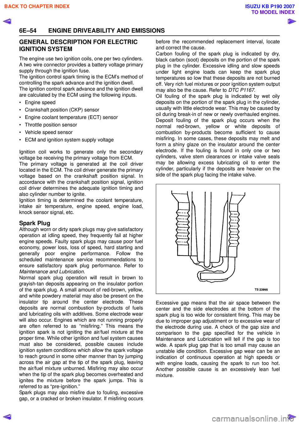
Excessive gap means that the air space between the
center and the side electrodes at the bottom of the
spark plug is too wide for consistent firing. This may be
due to improper gap adjustment or to excessive wear of
the electrode during use. A check of the gap size and
comparison to the gap specified for the vehicle in
Maintenance and Lubrication will tell if the gap is too
wide. A spark plug gap that is too small may cause an
unstable idle condition. Excessive gap wear can be an
indication of continuous operation at high speeds or
with engine loads, causing the spark to run too hot.
Another possible cause is an excessively lean fuel
mixture.
BACK TO CHAPTER INDEX
TO MODEL INDEX
ISUZU KB P190 2007
Page 2225 of 6020
ENGINE DRIVEABILITY AND EMISSIONS 6E–55
Low or high spark plug installation torque or improper
seating can result in the spark plug running too hot and
can cause excessive center electrode wear. The plug
and the cylinder head seats must be in good contact for
proper heat transfer and spark plug cooling. Dirty or
damaged threads in the head or on the spark plug can
keep it from seating even though the proper torque is
applied. Once spark plugs are properly seated, tighten
them to the torque shown in the Specifications Table.
Low torque may result in poor contact of the seats due
to a loose spark plug. Over tightening may cause the
spark plug shell to be stretched and will result in poor
contact between the seats. In extreme cases, exhaust
blow-by and damage beyond simple gap wear may
occur.
Cracked or broken insulators may be the result of
improper installation, damage during spark plug re-
gapping, or heat shock to the insulator material. Upper
insulators can be broken when a poorly fitting tool is
used during installation or removal, when the spark plug
is hit from the outside, or is dropped on a hard surface.
Cracks in the upper insulator may be inside the shell
and not visible. Also, the breakage may not cause
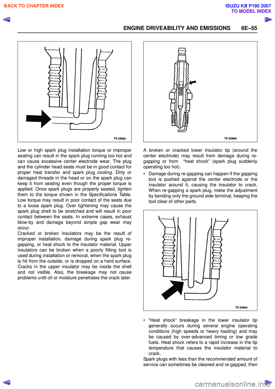
problems until oil or moisture penetrates the crack later. A broken or cracked lower insulator tip (around the
center electrode) may result from damage during re-
gapping or from “heat shock” (spark plug suddenly
operating too hot).
• Damage during re-gapping can happen if the gapping tool is pushed against the center electrode or the
insulator around it, causing the insulator to crack.
When re-gapping a spark plug, make the adjustment
by bending only the ground side terminal, keeping the
tool clear of other parts.
• “Heat shock” breakage in the lower insulator tip generally occurs during several engine operating
conditions (high speeds or heavy loading) and may
be caused by over-advanced timing or low grade
fuels. Heat shock refers to a rapid increase in the tip
temperature that causes the insulator material to
crack.
Spark plugs with less than the recommended amount of
service can sometimes be cleaned and re-gapped, then
BACK TO CHAPTER INDEX
TO MODEL INDEX
ISUZU KB P190 2007
Page 2518 of 6020

Engine Mechanical – V6 Page 6A1–39
2.16 Cylinder Leakage Test
A leakage test may be performed to measure cylinder/combustion chamber leakage. High cylinder leakage may indicate
one or more of the following:
• worn or burnt valves,
• broken valve springs,
• stuck valve lifters,
• incorrect valve lash/adjustment,
• damaged piston,
• worn piston rings,
• worn or scored cylinder bore,
• damaged cylinder head gasket,
• cracked or damaged cylinder head, or
• cracked or damaged engine block.
1 Disconnect the battery ground negative cable.
2 Remove the spark plugs from all cylinders, refer to 6C1-3 Engine Management – V6 – Service Operations.
3 Rotate the crankshaft to place the piston in the cylinder being tested at top dead centre (TDC) of the compression stroke.
4 Install a commercially available cylinder head leak down tester into the spark plug hole.
NOTE
If required, hold the crankshaft balancer bolt to
prevent the engine from rotating.
5 Apply shop air pressure to the cylinder head leak down tester and adjust according to the manufacturers instructions.
6 Record the cylinder leakage value. Cylinder leakage that exceeds 25 percent is considered excessive and may require component service. In excessive leakage situations, inspect for the following conditions:
• air leakage sounds at the throttle body or air inlet duct that may indicate a worn or burnt intake valve or a
broken valve spring,
• air leakage sounds at the exhaust system tailpipe that may indicate a worn or burnt exhaust valve or a broken
valve spring,
• air leakage sounds from the crankcase, oil level indicator tube, or oil fill tube that may indicate worn piston
rings, a damaged piston, a worn or scored cylinder bore, a damaged engine block or a damaged cylinder
head, or
• air bubbles in the cooling system may indicate a damaged cylinder head or a damaged cylinder head gasket.
7 Perform the leakage test on the remaining cylinders and record the values.
2.17 Engine Oil Consumption Diagnosis
Definition
Excessive oil consumption (not due to leaks) is the use of 3 litres or more of engine oil within 10,000 kilometres. Prior to
performing oil pressure testing, a preliminary inspection of the vehicle should be performed. During the preliminary visual
inspection, the following likely causes of excessive oil usage should be investigated.
Cause Correction
External oil leaks. Refer to 2.18 Engine Oil Leak Diagnosis.
Incorrect oil level or reading of the oil level indicator. Check for the correct oil level, refer to 3.1 Engine Oil.
Incorrect oil viscosity. Replace the engine oil, using the recommended SAE grade
of engine oil, refer to 3.1 Engine Oil.
Continuous high-speed driving or severe usage. Service vehicle more frequently, refer to 0B Lubrication and
Service.
Crankcase ventilation system restricted or malfunctioning. Repair or replace crankcase ventilation system components as required, refer to 6C1-3 Engine Management – V6 –
Service Operations.
BACK TO CHAPTER INDEX
TO MODEL INDEX
ISUZU KB P190 2007
Page 2519 of 6020
Engine Mechanical – V6 Page 6A1–40
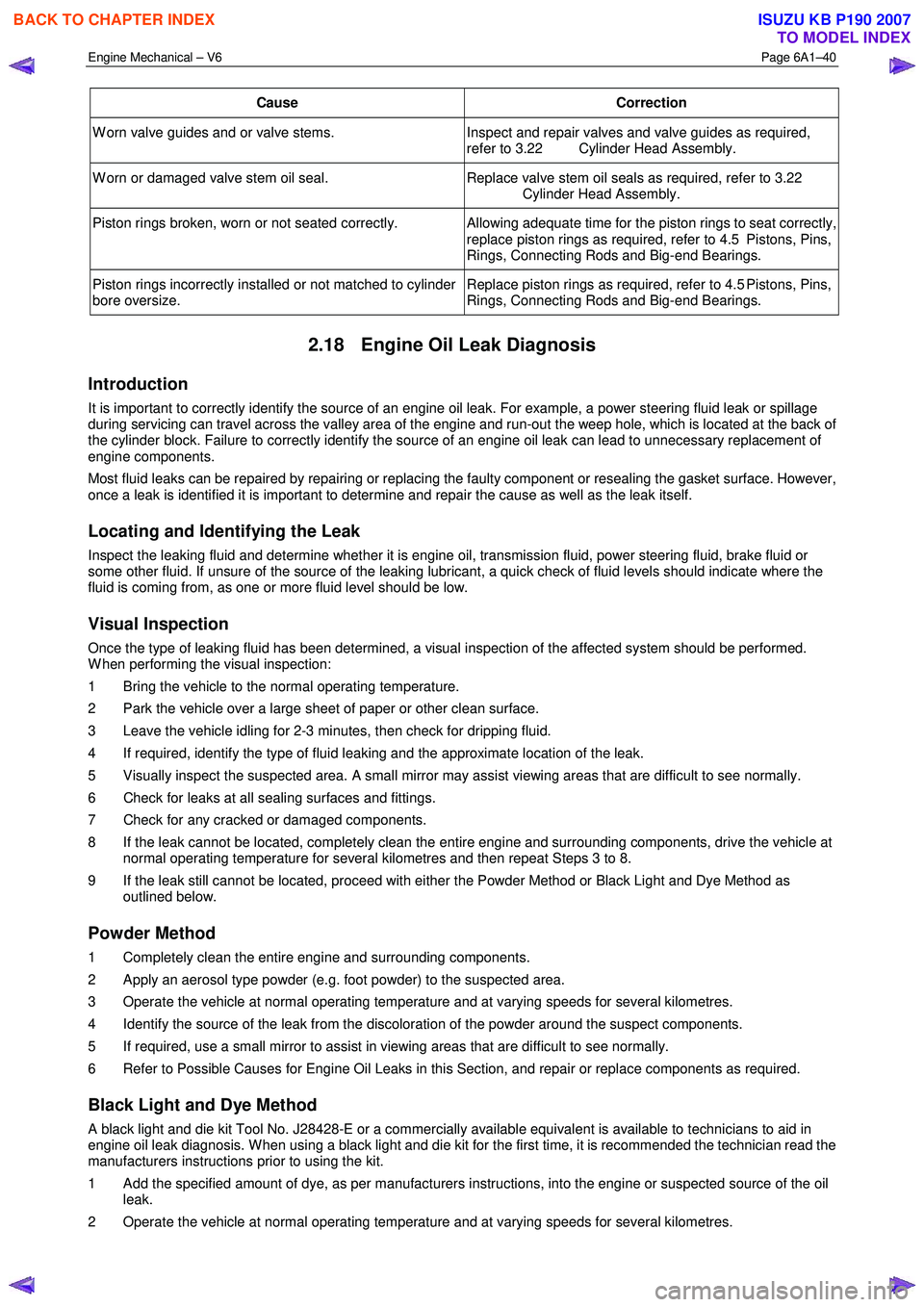
Cause Correction
W orn valve guides and or valve stems. Inspect and repair valves and valve guides as required,
refer to 3.22 Cylinder Head Assembly.
W orn or damaged valve stem oil seal. Replace valve stem oil seals as required, refer to 3.22
Cylinder Head Assembly.
Piston rings broken, worn or not seated correctly. Allowing adequate time for the piston rings to seat correctly,
replace piston rings as required, refer to 4.5 Pistons, Pins,
Rings, Connecting Rods and Big-end Bearings.
Piston rings incorrectly installed or not matched to cylinder
bore oversize. Replace piston rings as required, refer to 4.5 Pistons, Pins,
Rings, Connecting Rods and Big-end Bearings.
2.18 Engine Oil Leak Diagnosis
Introduction
It is important to correctly identify the source of an engine oil leak. For example, a power steering fluid leak or spillage
during servicing can travel across the valley area of the engine and run-out the weep hole, which is located at the back of
the cylinder block. Failure to correctly identify the source of an engine oil leak can lead to unnecessary replacement of
engine components.
Most fluid leaks can be repaired by repairing or replacing the faulty component or resealing the gasket surface. However,
once a leak is identified it is important to determine and repair the cause as well as the leak itself.
Locating and Identifying the Leak
Inspect the leaking fluid and determine whether it is engine oil, transmission fluid, power steering fluid, brake fluid or
some other fluid. If unsure of the source of the leaking lubricant, a quick check of fluid levels should indicate where the
fluid is coming from, as one or more fluid level should be low.
Visual Inspection
Once the type of leaking fluid has been determined, a visual inspection of the affected system should be performed.
W hen performing the visual inspection:
1 Bring the vehicle to the normal operating temperature.
2 Park the vehicle over a large sheet of paper or other clean surface.
3 Leave the vehicle idling for 2-3 minutes, then check for dripping fluid.
4 If required, identify the type of fluid leaking and the approximate location of the leak.
5 Visually inspect the suspected area. A small mirror may assist viewing areas that are difficult to see normally.
6 Check for leaks at all sealing surfaces and fittings.
7 Check for any cracked or damaged components.
8 If the leak cannot be located, completely clean the entire engine and surrounding components, drive the vehicle at normal operating temperature for several kilometres and then repeat Steps 3 to 8.
9 If the leak still cannot be located, proceed with either the Powder Method or Black Light and Dye Method as outlined below.
Powder Method
1 Completely clean the entire engine and surrounding components.
2 Apply an aerosol type powder (e.g. foot powder) to the suspected area.
3 Operate the vehicle at normal operating temperature and at varying speeds for several kilometres.
4 Identify the source of the leak from the discoloration of the powder around the suspect components.
5 If required, use a small mirror to assist in viewing areas that are difficult to see normally.
6 Refer to Possible Causes for Engine Oil Leaks in this Section, and repair or replace components as required.
Black Light and Dye Method
A black light and die kit Tool No. J28428-E or a commercially available equivalent is available to technicians to aid in
engine oil leak diagnosis. W hen using a black light and die kit for the first time, it is recommended the technician read the
manufacturers instructions prior to using the kit.
1 Add the specified amount of dye, as per manufacturers instructions, into the engine or suspected source of the oil leak.
2 Operate the vehicle at normal operating temperature and at varying speeds for several kilometres.
BACK TO CHAPTER INDEX
TO MODEL INDEX
ISUZU KB P190 2007
Page 2520 of 6020
Engine Mechanical – V6 Page 6A1–41
3 W ith the vehicle parked on a flat level surface, aim the black light at the suspected component/s. The dyed fluid will
appear as a yellow path leading to the oil leak source
4 Refer to Possible Causes for Engine Oil Leaks in this Section, and repair or replace components as required.
Possible Causes for Engine Oil Leaks
Common possible causes for engine oil leaks are:
• higher than recommended fluid levels,
• higher than recommended fluid pressures,
• blocked or faulty fluid filters or pressure relief valve,
• blocked or faulty engine ventilation system,
• incorrectly tightened or damaged fasteners,
• cracked or porous components,
• incorrect gaskets or sealants used,
• incorrect gaskets or sealant installation,
• damaged or worn gaskets or seals, and
• damaged or worn sealing surfaces.
BACK TO CHAPTER INDEX
TO MODEL INDEX
ISUZU KB P190 2007
Page 2532 of 6020
Engine Mechanical – V6 Page 6A1–53
3 Minor Service Operations
ATTENTION
The V6 engine is a combination of numerous components, containing machined, honed, polished and lapped
surfaces manufactured on the latest, high technology production equipment. Many of the components
contain tolerances measured in thousandths of a millimetre. Consequently, when any engine component is to
be serviced, care and cleanliness are extremely important.
Prior to re-assembly of the engine, all components must be cleaned and inspected in accordance with the
relevant clean and inspect procedures throughout this Section, and replaced or repaired where required.
In addition to cleaning and inspecting components, a liberal coating of engine oil should be applied to friction
surfaces during assembly to protect and lubricate the surfaces on initial operation.
When performing any service operation, it should be understood that correct cleaning and protection of
machined surfaces and friction areas is part of the repair procedure. This is considered standard workshop
practice, even if not specifically stated. Torque values must be used as specified during reassembly to
ensure correct retention of all components.
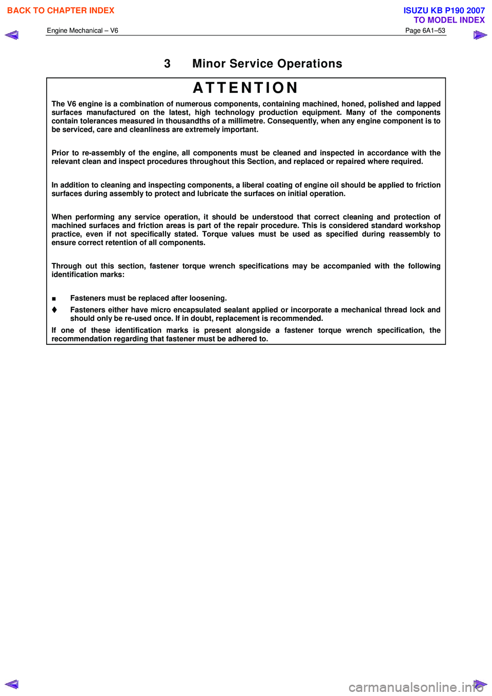
Through out this section, fastener torque wrench specifications may be accompanied with the following
identification marks:
■ Fasteners must be replaced after loosening.
Fasteners either have micro encapsulated sealant applied or incorporate a mechanical thread lock and
should only be re-used once. If in doubt, replacement is recommended.
If one of these identification marks is present alongside a fastener torque wrench specification, the
recommendation regarding that fastener must be adhered to.
BACK TO CHAPTER INDEX
TO MODEL INDEX
ISUZU KB P190 2007