2007 ISUZU KB P190 recommended oil
[x] Cancel search: recommended oilPage 830 of 6020

ENGINE MECHANICAL 6A – 25
Replenished Engine Oil MAX lit (US/UK gal)
Condition
Model Engine Dry
W ith oil filter
replacement W ithout oil
filter
replacement
4 × 2
4 × 4
(4JA1L/TC)6.2 (1.64/1.36) 5.2 ∼ 4.2
(1.37 ∼ 1.11
/ 1.14 ∼ 0.92) 4.5
∼ 3.5
(1.19 ∼ 0.93
/ 0.99 ∼ 0.77)
4 × 2
(4JH1TC)
6.2 (1.64/1.36) 5.2
∼ 4.2
(1.37 ∼ 1.11
/ 1.14 ∼ 0.92) 4.5
∼ 3.5
(1.19 ∼ 0.93
/ 0.99 ∼ 0.77)
4 × 4
(4JH1TC) 7.0 (1.85/1.54) 6.2 ∼ 5.2
(1.64 ∼ 1.37
/ 1.36 ∼ 1.14) 5.3
∼ 4.3
(1.72 ∼ 1.14
/ 1.17 ∼ 0.95)
9. Start the engine and check for oil leakage from the
main oil filter.
RTW 66ASH003201
FUEL SYSTEM
Fuel Filter Replacement Procedure
1. Remove the fuel filter by turning it counterclockwise with a filter wrench.
Filter W rench: 5-8840-0253-0 (J-22700)
Note:
Be careful not to spill the fuel in the filter cartridge.
RTW 66ASH003301
2. Clean the fuel filter cartridge fitting faces. This will allow the new fuel filter to seat properly
3. Apply a light coat of engine oil to the O-ring.
4. Turn in the fuel filter until the sealing face comes in contact with the O-ring.
5. Turn in the fuel filter an additional 2/3 of a turn with a filter wrench.
Filter W rench : 5-8840-0253-0 (J-22700)
6. Operate the priming pump until the air discharged completely from fuel system.
7. Start the engine and check for fuel leakage.
Note:
The use of an ISUZU genuine fuel filter is strongly
recommended.
041RY00009
BACK TO CHAPTER INDEX
TO MODEL INDEX
ISUZU KB P190 2007
Page 910 of 6020

ENGINE MECHANICAL 6A – 105
5. Crankshaft Thrust Bearing
Apply an ample coat of engine oil to the thrust bearings
before installation.
Install the thrust bearings to the crankshaft center journal.
The thrust bearing oil grooves must be facing the sliding
faces.
6. Crankshaft Bearing Cap With Lower Bearing
Before the crankshaft bearing installation, select the
appropriate bearings in accordance with the description in
CRANK BEARING SELECTION of INSPECTION AND
REPAIR.
1. Apply the recommended liquid gasket or its equivalent to the No. 5 crankshaft bearing cap cylinder body fitting
surfaces at the points shown in the illustration.
NOTE:
Be sure that the bearing cap fitting surface is
completely free of oil before applying the liquid
gasket. Three bond 1207B Do not allow the liquid
gasket to obstruct the cylinder thread holes and
bearings.
ThreeBond 1207B is a fast-drying liquid gasket.
Tighten the bearing caps immediately after applying
the gasket.
2. Install the bearing caps with the bearing cap head
arrow mark facing the front of the engine.The bearing
cap numbers must be facing up.
3. Apply engine oil to the crankshaft bearing cap bolts.
4. Tighten the crankshaft bearing cap bolts to the
specified torque a little at time in the sequence shown
in the illustration.
Crankshaft Bearing Cap Torque N·m(kg·m/lbft)
167 (17/123)
5. Check to see the crankshaft turns smoothly by rotating it manually.
015LX115
015LX127
015LX128
015LX129
BACK TO CHAPTER INDEX
TO MODEL INDEX
ISUZU KB P190 2007
Page 914 of 6020

ENGINE MECHANICAL 6A – 109
16. Crank Case
1. Apply the recommended liquid gasket (Three bond 1207B) or its equivalent to arch gasket fitting surface
as shown in the illustration.
2. Install the crankcase front gasket (1) to the timing gear case arches.
The gasket projection (2) must be facing forward.
NOTE:
ThreeBond 1207B is a fast-drying liquid gasket.
Install the arch packing to the crankcase immediately
aftter applying the gasket.
3. Install the rear arch gasket (2) to the No. 5 bearing
cap. Use your fingers to push the arch gasket into the
bearing cap groove.Take care not to scratch the arch
gasket outer surface.
Also apply the recommended liquid gasket (1207C) or
its equivalent to arch gasket fitting area as indicated in
the illustration.
4. Apply the recommended liquid gasket or its equivalent to groove of the crankcase fitting surface as shown in
the illustration.
NOTE:
Be sure that the crank case fitting surface is
completely free of oil and dust before applying the
liquid gasket.
5. Install the crank case to the cylinder body.
6. Tighten the crank case bolts to the specified torque a little at a time in the sequence shown in the illustration.
Crank Case Bolt Torque N·m(kg·m/lbft)
19 (1.9/14)
013LV003
013RW 012
013RW 011
013R100001
BACK TO CHAPTER INDEX
TO MODEL INDEX
ISUZU KB P190 2007
Page 1493 of 6020

ENGINE MECHANICAL (4JK1/4JJ1) 6A-133
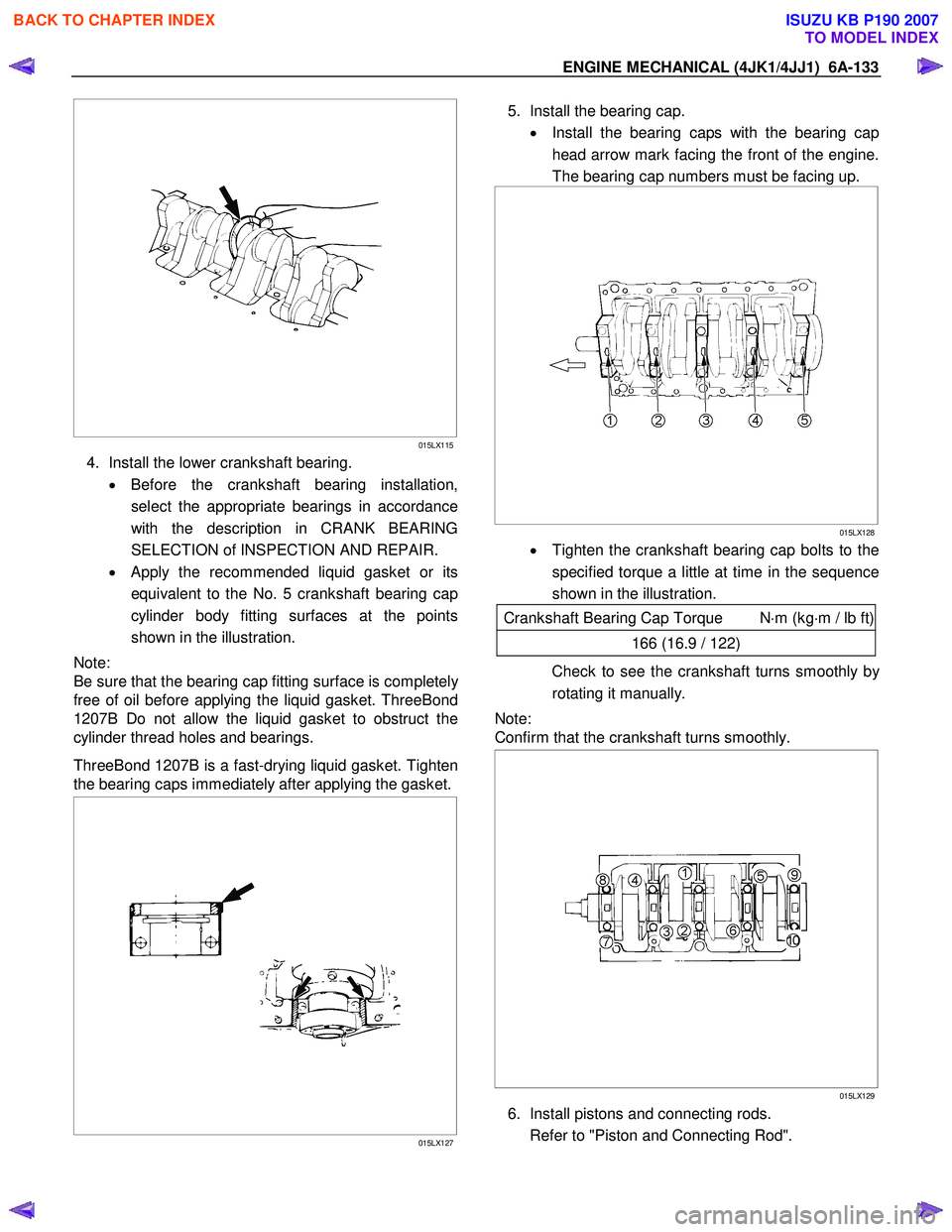
015LX115
4. Install the lower crankshaft bearing.
• Before the crankshaft bearing installation,
select the appropriate bearings in accordance
with the description in CRANK BEARING
SELECTION of INSPECTION AND REPAIR.
• Apply the recommended liquid gasket or its
equivalent to the No. 5 crankshaft bearing cap
cylinder body fitting surfaces at the points
shown in the illustration.
Note:
Be sure that the bearing cap fitting surface is completel
y
free of oil before applying the liquid gasket. ThreeBond
1207B Do not allow the liquid gasket to obstruct the
cylinder thread holes and bearings.
ThreeBond 1207B is a fast-drying liquid gasket. Tighten
the bearing caps immediately after applying the gasket.
015LX127
5. Install the bearing cap.
• Install the bearing caps with the bearing cap
head arrow mark facing the front of the engine.
The bearing cap numbers must be facing up.
015LX128
• Tighten the crankshaft bearing cap bolts to the
specified torque a little at time in the sequence
shown in the illustration.
Crankshaft Bearing Cap Torque N ⋅m (kg ⋅m / lb ft)
166 (16.9 / 122)
Check to see the crankshaft turns smoothly by
rotating it manually.
Note:
Confirm that the crankshaft turns smoothly.
015LX129
6. Install pistons and connecting rods.
Refer to "Piston and Connecting Rod".
BACK TO CHAPTER INDEX
TO MODEL INDEX
ISUZU KB P190 2007
Page 2012 of 6020

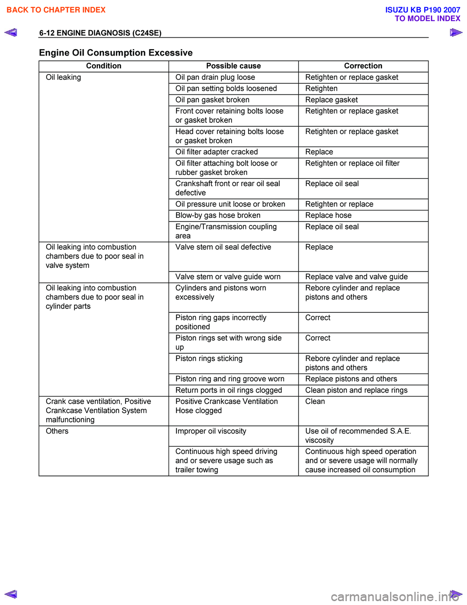
6-12 ENGINE DIAGNOSIS (C24SE)
Engine Oil Consumption Excessive
Condition Possible cause Correction
Oil leaking Oil pan drain plug loose Retighten or replace gasket
Oil pan setting bolds loosened Retighten
Oil pan gasket broken Replace gasket
Front cover retaining bolts loose
or gasket broken Retighten or replace gasket
Head cover retaining bolts loose
or gasket broken Retighten or replace gasket
Oil filter adapter cracked Replace
Oil filter attaching bolt loose or
rubber gasket broken Retighten or replace oil filter
Crankshaft front or rear oil seal
defective Replace oil seal
Oil pressure unit loose or broken Retighten or replace
Blow-by gas hose broken Replace hose
Engine/Transmission coupling
area Replace oil seal
Oil leaking into combustion
chambers due to poor seal in
valve system Valve stem oil seal defective Replace
Valve stem or valve guide worn Replace valve and valve guide
Oil leaking into combustion
chambers due to poor seal in
cylinder parts Cylinders and pistons worn
excessively Rebore cylinder and replace
pistons and others
Piston ring gaps incorrectly
positioned Correct
Piston rings set with wrong side
up Correct
Piston rings sticking Rebore cylinder and replace
pistons and others
Piston ring and ring groove worn Replace pistons and others
Return ports in oil rings clogged Clean piston and replace rings
Crank case ventilation, Positive
Crankcase Ventilation System
malfunctioning Positive Crankcase Ventilation
Hose clogged Clean
Others
Improper oil viscosity Use oil of recommended S.A.E.
viscosity
Continuous high speed driving
and or severe usage such as
trailer towing Continuous high speed operation
and or severe usage will normally
cause increased oil consumption
BACK TO CHAPTER INDEX
TO MODEL INDEX
ISUZU KB P190 2007
Page 2017 of 6020

ENGINE MECHANICAL (C24SE) 6A-3
PAGE
ENGINE EXTERNAL PARTS ........................................................................................... 6A-65 Radiator ....................................................................................................................... 6A-65
Thermostat .................................................................................................................. 6A -66
Water Pump ................................................................................................................. 6A- 66
Coating sealing surfaces with Silicone Grease ....................................................... 6A-67
Alternator ..................................................................................................................... 6A-67
Starter ........................................................................................................................ .. 6A-67
V-belt Tension of Alternator ....................................................................................... 6A-68
FUEL INJECTION SYSTEM ............................................................................................. 6A-70 Map Sensor ................................................................................................................. 6A- 70
Pressure Regulator..................................................................................................... 6A-70
ECM (Engine Control Module) ................................................................................... 6A-70
ECT............................................................................................................................ ... 6A-71
Idle Air Control(IAC) Valve ......................................................................................... 6A-71
Ignition Coil ................................................................................................................. 6A-71
Crank Position Sensor ............................................................................................... 6A-72
FUEL INJECTOR .............................................................................................................. 6A- 73
Knock Sensor.............................................................................................................. 6A-7 3
Oxygen Sensor............................................................................................................ 6A-74
Throttle Valve Position Sensor .................................................................................. 6A-74
Acclelerator Pedal and Cable .................................................................................... 6A-74
Air Cleaner Filter ......................................................................................................... 6A- 75
Spark Plug Thread ...................................................................................................... 6A-76
TECHNICAL DATA ........................................................................................................... 6A-77
Recommended Troque Values .................................................................................. 6A-88
SPECIAL SERVICE TOOL ............................................................................................... 6A-89
BACK TO CHAPTER INDEX
TO MODEL INDEX
ISUZU KB P190 2007
Page 2027 of 6020

ENGINE MECHANICAL (C24SE) 6A-13
Valve System C24SE
Actuation Type Direct-acting Inverted Bucked Tappet
Valve Clearance Adjustment Hydraulic
Valve Rotor Type None
Inlet-Valve Material Chromium Alloyed Steel
-Seat Insert MaterialSintered Iron
Exhaust-Valve Material Head: Cr-Mn-Ni Alloyed Shaft: Cr-Si Alloyed &Cr plated
-Seat Insert MaterialSintered Iron
Valve Spring Material GME 06 100-C1
Valve Guide Material QS 13 MR 00
Valve Seal Type Lip
Water Pump C24SE
Type Centrifugal
Drive-Material &Type HNBR Toothed-belt
Bearing Type Double Row Ball
Shaft Seal Type Mechanical Ceramic
Thermostat-Coolant C24SE
Type Bypass
Oil Pump & Filter C24SE
Type Gear Pump
Location Front of Engine
Drive Direct Crankshaft Driven
Filter Type Full Flow with Bypass for blocked filter
Oil & Oil Reservoir C24SE
Reservoir-Description & Location 1-piece below Engine
Reservoir Material Aluminum Alloy (pressure cast)
Replacement Oil Fill Volume
-W ith Filter change4.25liters
-W ithout Filter change 4.00liters
Recommended Oil-Run-in 10W /30SG
-Service (above-18°C) 10W /40SG
-Service (below-18°C) 5W /30SG
Oil Classification API&CCMC
Ignition Components C24SE
Spark Plugs Conventional
Type Electronic Spark Control
No. of Coils &Type 2 Solid State
Coil Location Engine-mounted
Ignition Lead Type Inductive (hi-resistance)
BACK TO CHAPTER INDEX
TO MODEL INDEX
ISUZU KB P190 2007
Page 2064 of 6020

6A-50 ENGINE MECHANICAL (C24SE)
Clean
Sealing surfaces.
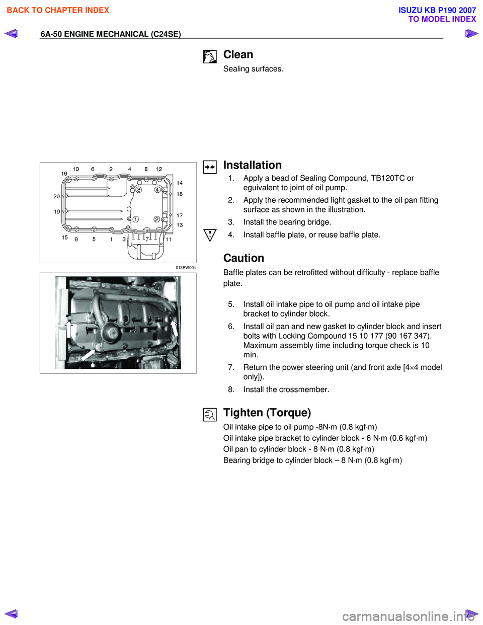
013RW 004
Installation
1. Apply a bead of Sealing Compound, TB120TC or eguivalent to joint of oil pump.
2. Apply the recommended light gasket to the oil pan fitting surface as shown in the illustration.
3. Install the bearing bridge.
4. Install baffle plate, or reuse baffle plate.
Caution
Baffle plates can be retrofitted without difficulty - replace baffle
plate.
5. Install oil intake pipe to oil pump and oil intake pipe bracket to cylinder block.
6. Install oil pan and new gasket to cylinder block and insert bolts with Locking Compound 15 10 177 (90 167 347).
Maximum assembly time including torque check is 10
min.
7. Return the power steering unit (and front axle [4 ×4 model
only]).
8. Install the crossmember.
Tighten (Torque)
Oil intake pipe to oil pump -8N ⋅m (0.8 kgf ⋅m)
Oil intake pipe bracket to cylinder block - 6 N ⋅m (0.6 kgf ⋅m)
Oil pan to cylinder block - 8 N ⋅m (0.8 kgf ⋅m)
Bearing bridge to cylinder block – 8 N ⋅m (0.8 kgf ⋅m)
BACK TO CHAPTER INDEX
TO MODEL INDEX
ISUZU KB P190 2007