Page 1411 of 6020
ENGINE MECHANICAL (4JK1/4JJ1) 6A-51
Removal
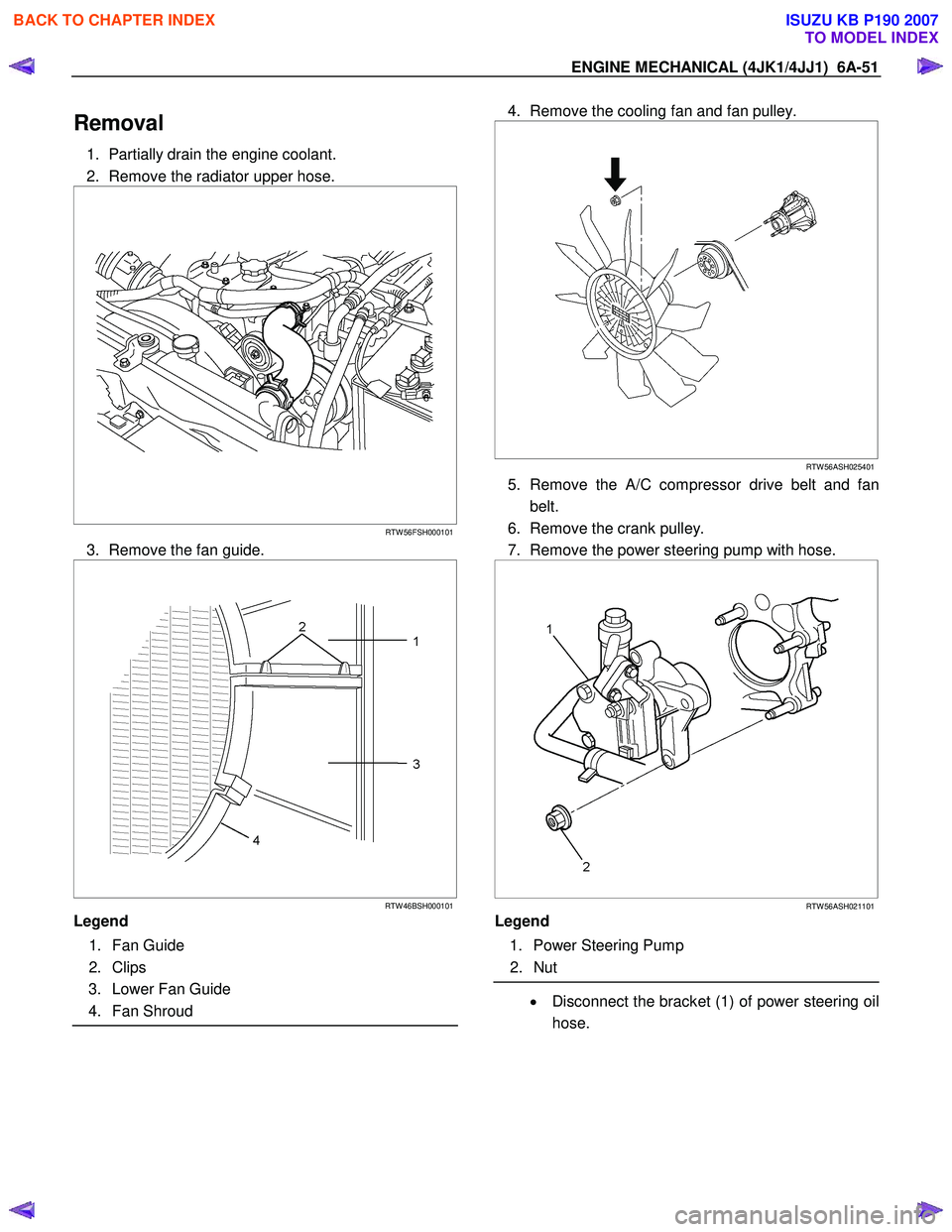
1. Partially drain the engine coolant.
2. Remove the radiator upper hose.
RTW 56FSH000101
3. Remove the fan guide.
RTW 46BSH000101
Legend
1. Fan Guide
2. Clips
3. Lower Fan Guide
4. Fan Shroud
4. Remove the cooling fan and fan pulley.
RTW 56ASH025401
5. Remove the A/C compressor drive belt and fan
belt.
6. Remove the crank pulley.
7. Remove the power steering pump with hose.
RTW 56ASH021101
Legend
1. Power Steering Pump
2. Nut
• Disconnect the bracket (1) of power steering oil
hose.
BACK TO CHAPTER INDEX
TO MODEL INDEX
ISUZU KB P190 2007
Page 1417 of 6020
ENGINE MECHANICAL (4JK1/4JJ1) 6A-57
6. Remove the M6 bolt from the idle gear A.
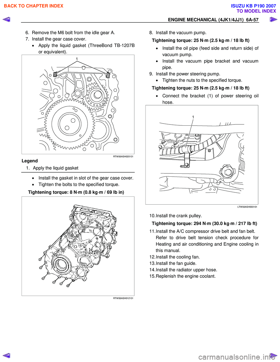
7. Install the gear case cover. • Apply the liquid gasket (ThreeBond TB-1207B
or equivalent).
RTW 56ASH020101
Legend
1. Apply the liquid gasket
• Install the gasket in slot of the gear case cover.
• Tighten the bolts to the specified torque.
Tightening torque: 8 N ⋅
⋅⋅
⋅
m (0.8 kg ⋅
⋅⋅
⋅
m / 69 lb in)
RTW 56ASH012101
8. Install the vacuum pump.
Tightening torque: 25 N ⋅
⋅⋅
⋅
m (2.5 kg ⋅
⋅⋅
⋅
m / 18 lb ft)
• Install the oil pipe (feed side and return side) o
f
vacuum pump.
• Install the vacuum pipe bracket and vacuum
pipe.
9. Install the power steering pump. • Tighten the nuts to the specified torque.
Tightening torque: 25 N ⋅
⋅⋅
⋅
m (2.5 kg ⋅
⋅⋅
⋅
m / 18 lb ft)
• Connect the bracket (1) of power steering oil
hose.
LTW 56ASH000101
10. Install the crank pulley.
Tightening torque: 294 N ⋅
⋅⋅
⋅
m (30.0 kg ⋅
⋅⋅
⋅
m / 217 lb ft)
11. Install the A/C compressor drive belt and fan belt.
Refer to drive belt tension check procedure fo
r
Heating and air conditioning and Engine cooling in
this manual.
12. Install the cooling fan.
13. Install the fan guide.
14. Install the radiator upper hose.
15. Replenish the engine coolant.
BACK TO CHAPTER INDEX
TO MODEL INDEX
ISUZU KB P190 2007
Page 1433 of 6020
ENGINE MECHANICAL (4JK1/4JJ1) 6A-73
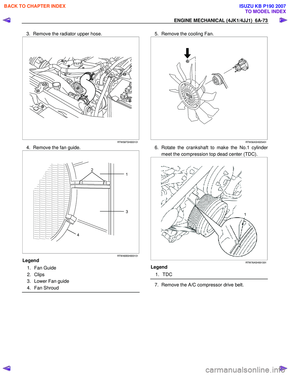
3. Remove the radiator upper hose.
RTW 56FSH000101
4. Remove the fan guide.
RTW 46BSH000101
Legend
1. Fan Guide
2. Clips
3. Lower Fan guide
4. Fan Shroud
5. Remove the cooling Fan.
RTW 56ASH025401
6. Rotate the crankshaft to make the No.1 cylinder
meet the compression top dead center (TDC).
RTW 76ASH001301
Legend
1. TDC
7. Remove the A/C compressor drive belt.
BACK TO CHAPTER INDEX
TO MODEL INDEX
ISUZU KB P190 2007
Page 1458 of 6020
6A-98 ENGINE MECHANICAL (4JK1/4JJ1)
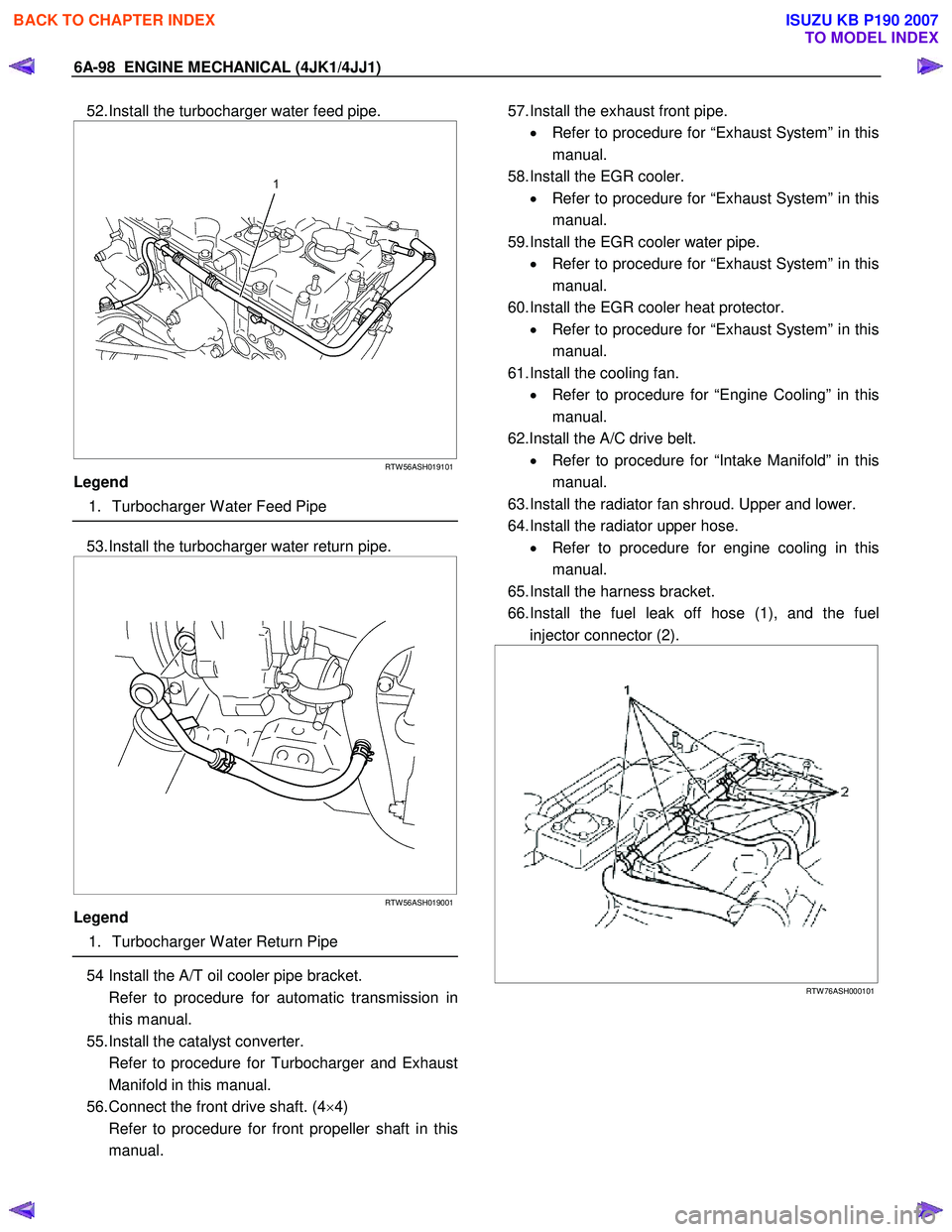
52. Install the turbocharger water feed pipe.
RTW 56ASH019101
Legend
1. Turbocharger W ater Feed Pipe
53. Install the turbocharger water return pipe.
RTW 56ASH019001
Legend
1. Turbocharger W ater Return Pipe
54 Install the A/T oil cooler pipe bracket.
Refer to procedure for automatic transmission in this manual.
55. Install the catalyst converter.
Refer to procedure for Turbocharger and Exhaust Manifold in this manual.
56. Connect the front drive shaft. (4 ×4)
Refer to procedure for front propeller shaft in this manual.
57. Install the exhaust front pipe.
• Refer to procedure for “Exhaust System” in this
manual.
58. Install the EGR cooler. • Refer to procedure for “Exhaust System” in this
manual.
59. Install the EGR cooler water pipe. • Refer to procedure for “Exhaust System” in this
manual.
60. Install the EGR cooler heat protector. • Refer to procedure for “Exhaust System” in this
manual.
61. Install the cooling fan. • Refer to procedure for “Engine Cooling” in this
manual.
62.Install the A/C drive belt. • Refer to procedure for “Intake Manifold” in this
manual.
63. Install the radiator fan shroud. Upper and lower.
64. Install the radiator upper hose. • Refer to procedure for engine cooling in this
manual.
65. Install the harness bracket.
66. Install the fuel leak off hose (1), and the fuel injector connector (2).
RTW 76ASH000101
BACK TO CHAPTER INDEX
TO MODEL INDEX
ISUZU KB P190 2007
Page 1516 of 6020
6A-156 ENGINE MECHANICAL (4JK1/4JJ1)
Oil Pump
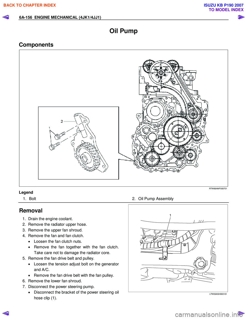
Components
RTW 66AMF000701
Legend 1. Bolt 2. Oil Pump Assembly
Removal
1. Drain the engine coolant.
2. Remove the radiator upper hose.
3. Remove the upper fan shroud.
4. Remove the fan and fan clutch. • Loosen the fan clutch nuts.
• Remove the fan together with the fan clutch.
Take care not to damage the radiator core.
5. Remove the fan drive belt and pulley. • Loosen the tension adjust bolt on the generato
r
and A/C.
• Remove the fan drive belt with the fan pulley.
6. Remove the lower fan shroud.
7. Disconnect the power steering pump. • Disconnect the bracket of the power steering oil
hose clip (1).
LTW 56ASH000101
BACK TO CHAPTER INDEX
TO MODEL INDEX
ISUZU KB P190 2007
Page 1520 of 6020
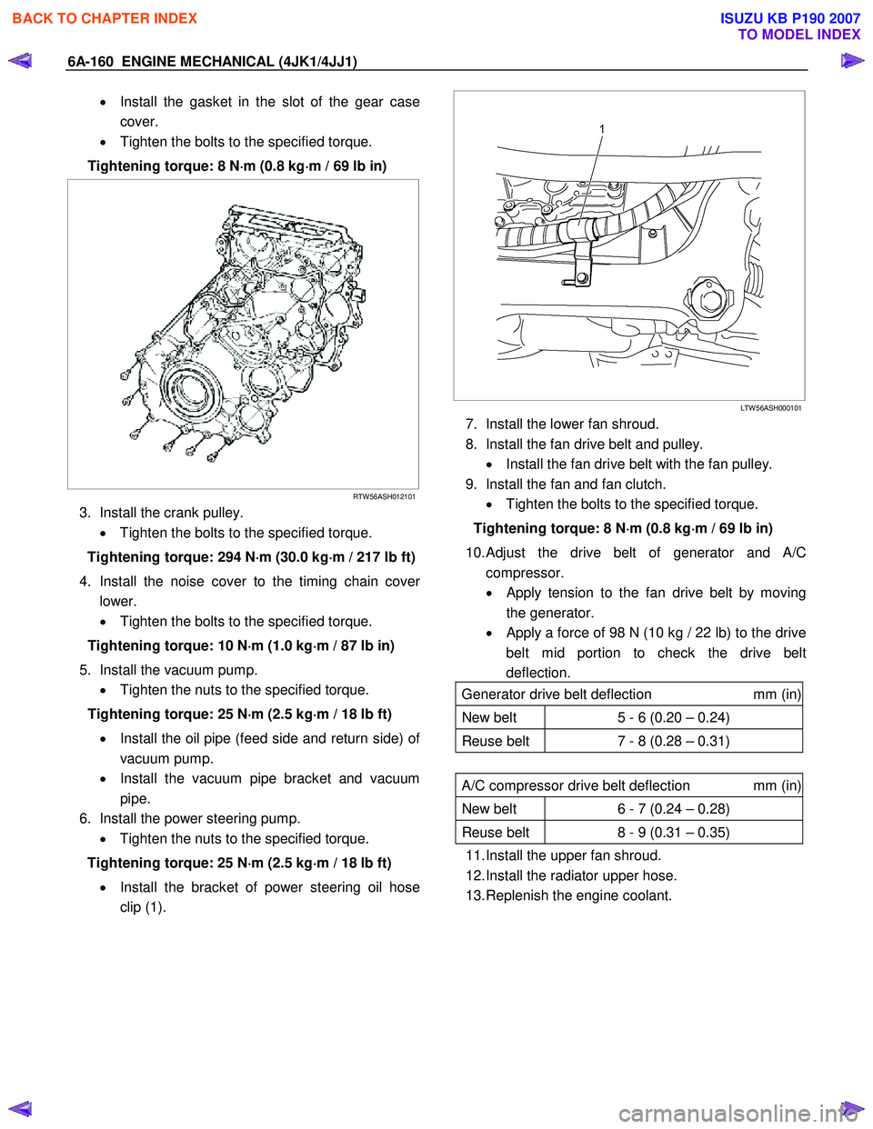
6A-160 ENGINE MECHANICAL (4JK1/4JJ1)
• Install the gasket in the slot of the gear case
cover.
• Tighten the bolts to the specified torque.
Tightening torque: 8 N ⋅
⋅⋅
⋅
m (0.8 kg ⋅
⋅⋅
⋅
m / 69 lb in)
RTW 56ASH012101
3. Install the crank pulley.
• Tighten the bolts to the specified torque.
Tightening torque: 294 N ⋅
⋅⋅
⋅
m (30.0 kg ⋅
⋅⋅
⋅
m / 217 lb ft)
4. Install the noise cover to the timing chain cove
r
lower.
• Tighten the bolts to the specified torque.
Tightening torque: 10 N ⋅
⋅⋅
⋅
m (1.0 kg ⋅
⋅⋅
⋅
m / 87 lb in)
5. Install the vacuum pump. • Tighten the nuts to the specified torque.
Tightening torque: 25 N ⋅
⋅⋅
⋅
m (2.5 kg ⋅
⋅⋅
⋅
m / 18 lb ft)
• Install the oil pipe (feed side and return side) o
f
vacuum pump.
• Install the vacuum pipe bracket and vacuum
pipe.
6. Install the power steering pump. • Tighten the nuts to the specified torque.
Tightening torque: 25 N ⋅
⋅⋅
⋅
m (2.5 kg ⋅
⋅⋅
⋅
m / 18 lb ft)
• Install the bracket of power steering oil hose
clip (1).
LTW 56ASH000101
7. Install the lower fan shroud.
8. Install the fan drive belt and pulley. • Install the fan drive belt with the fan pulley.
9. Install the fan and fan clutch. • Tighten the bolts to the specified torque.
Tightening torque: 8 N ⋅
⋅⋅
⋅
m (0.8 kg ⋅
⋅⋅
⋅
m / 69 lb in)
10.
Adjust the drive belt of generator and A/C
compressor.
• Apply tension to the fan drive belt by moving
the generator.
•
Apply a force of 98 N (10 kg / 22 lb) to the drive
belt mid portion to check the drive belt
deflection.
Generator drive belt deflection mm (in)
New belt 5 - 6 (0.20 – 0.24)
Reuse belt 7 - 8 (0.28 – 0.31)
A/C compressor drive belt deflection mm (in)
New belt 6 - 7 (0.24 – 0.28)
Reuse belt 8 - 9 (0.31 – 0.35)
11. Install the upper fan shroud.
12. Install the radiator upper hose.
13. Replenish the engine coolant.
BACK TO CHAPTER INDEX
TO MODEL INDEX
ISUZU KB P190 2007
Page 1524 of 6020
ENGINE COOLING (4JK1/4JJ1) 6B-1
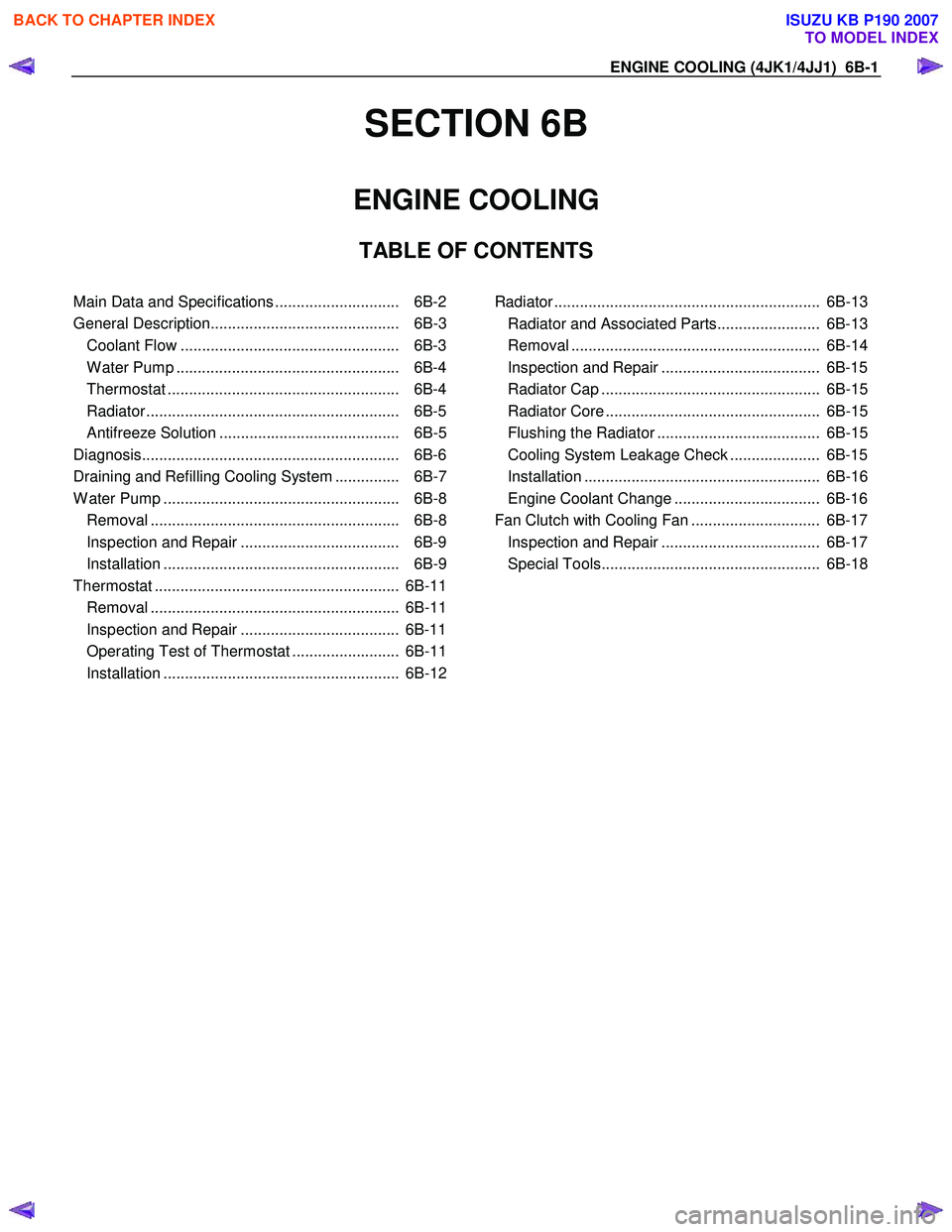
SECTION 6B
ENGINE COOLING
TABLE OF CONTENTS
Main Data and Specifications ............................. 6B-2
General Description............................................ 6B-3 Coolant Flow ................................................... 6B-3
W ater Pump .................................................... 6B-4
Thermostat ...................................................... 6B-4
Radiator ........................................................... 6B-5
Antifreeze Solution .......................................... 6B-5
Diagnosis............................................................ 6B-6
Draining and Refilling Cooling System ............... 6B-7
W ater Pump ....................................................... 6B-8 Removal .......................................................... 6B-8
Inspection and Repair ..................................... 6B-9
Installation ....................................................... 6B-9
Thermostat ......................................................... 6B-11 Removal .......................................................... 6B-11
Inspection and Repair ..................................... 6B-11
Operating Test of Thermostat ......................... 6B-11
Installation ....................................................... 6B-12
Radiator .............................................................. 6B-13 Radiator and Associated Parts........................ 6B-13
Removal .......................................................... 6B-14
Inspection and Repair ..................................... 6B-15
Radiator Cap ................................................... 6B-15
Radiator Core .................................................. 6B-15
Flushing the Radiator ...................................... 6B-15
Cooling System Leakage Check ..................... 6B-15
Installation ....................................................... 6B-16
Engine Coolant Change .................................. 6B-16
Fan Clutch with Cooling Fan .............................. 6B-17 Inspection and Repair ..................................... 6B-17
Special Tools................................................... 6B-18
BACK TO CHAPTER INDEX
TO MODEL INDEX
ISUZU KB P190 2007
Page 1525 of 6020
6B-2 ENGINE COOLING (4JK1/4JJ1)
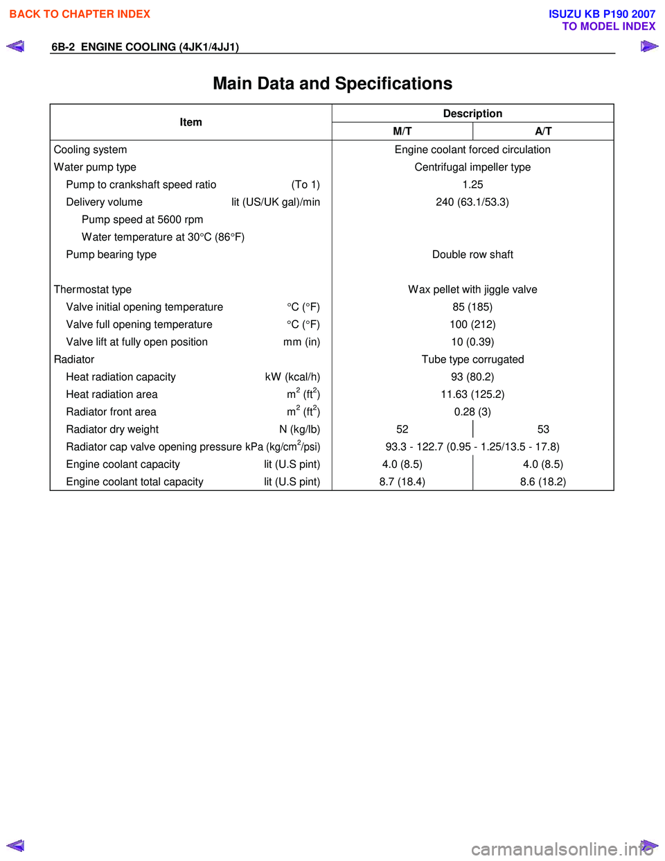
Main Data and Specifications
Description Item
M/T A/T
Cooling system
W ater pump type
Pump to crankshaft speed ratio (To 1)
Delivery volume lit (US/UK gal)/min
Pump speed at 5600 rpm
W ater temperature at 30 °C (86 °F)
Pump bearing type
Thermostat type
Valve initial opening temperature °C ( °F)
Valve full opening temperature °C ( °F)
Valve lift at fully open position mm (in) Engine coolant forced circulation
Centrifugal impeller type 1.25
240 (63.1/53.3)
Double row shaft
W ax pellet with jiggle valve 85 (185)
100 (212) 10 (0.39)
Radiator Tube type corrugated
Heat radiation capacity kW (kcal/h) 93 (80.2)
Heat radiation area m2 (ft2) 11.63 (125.2)
Radiator front area m2 (ft2) 0.28 (3)
Radiator dry weight N (kg/lb) 52 53
Radiator cap valve opening pressure kPa (kg/cm2/psi) 93.3 - 122.7 (0.95 - 1.25/13.5 - 17.8)
Engine coolant capacity lit (U.S pint) 4.0 (8.5) 4.0 (8.5)
Engine coolant total capacity lit (U.S pint) 8.7 (18.4) 8.6 (18.2)
BACK TO CHAPTER INDEX
TO MODEL INDEX
ISUZU KB P190 2007