Page 2078 of 6020
6A-64 ENGINE MECHANICAL (C24SE)
Important!
Do not loosen or open the radiator cap when coolant is hot.
Doing so may cause hot water or steam to splash out, resulting
in burn. W hen opening the radiator cap, be sure to confirm the
coolant is cold. Cover a thick cloth over the cap and loosen it
slowly to reduce pressure, then open the cap.
6. Close the radiator cap firmly and run the engine at approx. 2000 rpm. In addition, set the heater temperature
adjuster to the max position to circulate coolant in the
heater conduit system.
7. Confirm that the temperature gauge reads half or more of full scale and that the thermostat is activated.
Then continue idling 5 minutes more and switch off the
engine, and allow it to cool.
8. After the engine cools down, check the coolant level and refill it if necessary. W hen the level is lowered extremely,
check the coolant conduit system and reservoir hose for
leak.
9. Pour coolant into the reservoir to MAX level.
Refill Coolant
Important!
After closing the cooling system, let engine run warm until
thermostat opens (coolant approx. 92 °C/197.6F)
Inspection
Coolant level
Allow engine to cool. If necessary, refill coolant.
Check that cooling system self-bleeds during engine warming-
up phase.
Ignition Timing, Check
No Adjustment
BACK TO CHAPTER INDEX
TO MODEL INDEX
ISUZU KB P190 2007
Page 2079 of 6020
ENGINE MECHANICAL (C24SE) 6A-65
ENGINE EXTERNAL PARTS
Radiator
Removal
1. Disconnect battery ground cable.
2. Loosen a drain plug to drain EC.
3. Disconnect radiator inlet hose and outlet hose from the engine.
RTW 46BSH000101
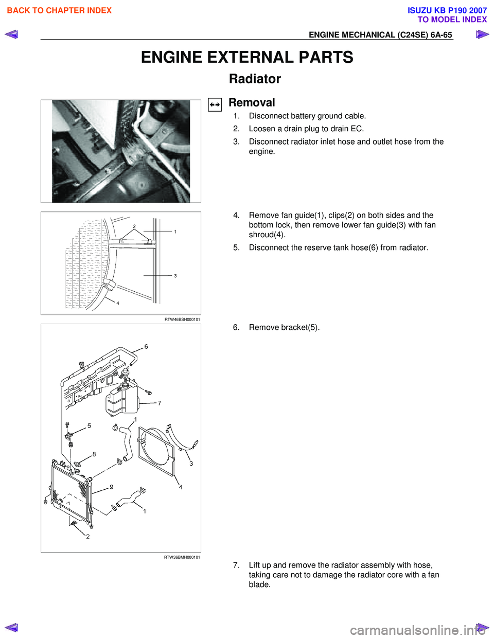
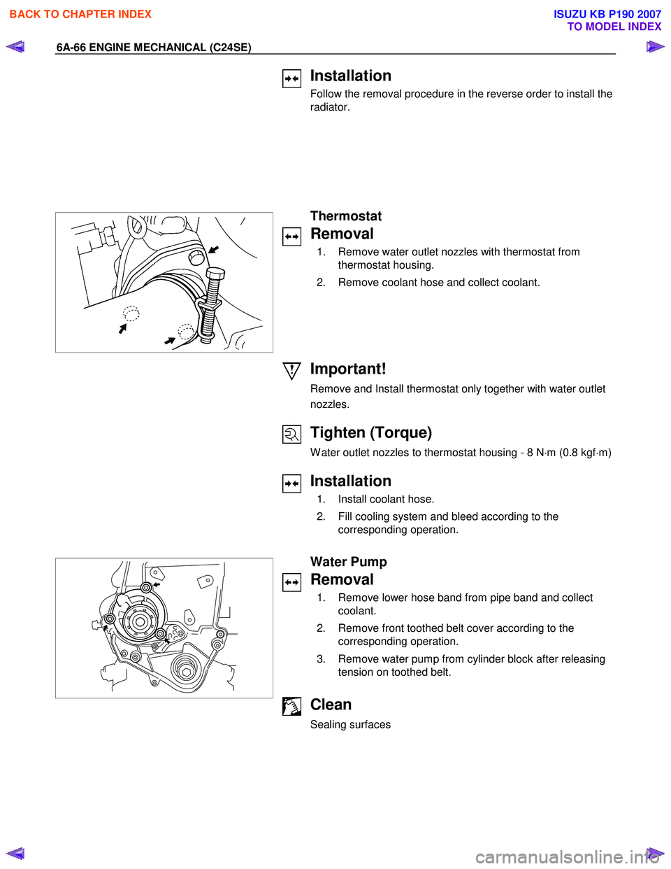
4. Remove fan guide(1), clips(2) on both sides and the
bottom lock, then remove lower fan guide(3) with fan
shroud(4).
5. Disconnect the reserve tank hose(6) from radiator.
RTW 36BMH000101
6. Remove bracket(5).
7. Lift up and remove the radiator assembly with hose,
taking care not to damage the radiator core with a fan
blade.
BACK TO CHAPTER INDEX
TO MODEL INDEX
ISUZU KB P190 2007
Page 2080 of 6020
6A-66 ENGINE MECHANICAL (C24SE)
Installation
Follow the removal procedure in the reverse order to install the
radiator.
Thermostat
Removal
1. Remove water outlet nozzles with thermostat from thermostat housing.
2. Remove coolant hose and collect coolant.
Important!
Remove and Install thermostat only together with water outlet
nozzles.
Tighten (Torque)
W ater outlet nozzles to thermostat housing - 8 N ⋅m (0.8 kgf ⋅m)
Installation
1. Install coolant hose.
2. Fill cooling system and bleed according to the corresponding operation.
Water Pump
Removal
1. Remove lower hose band from pipe band and collect coolant.
2. Remove front toothed belt cover according to the corresponding operation.
3. Remove water pump from cylinder block after releasing tension on toothed belt.
Clean
Sealing surfaces
BACK TO CHAPTER INDEX
TO MODEL INDEX
ISUZU KB P190 2007
Page 2092 of 6020
6A-78 ENGINE MECHANICAL (C24SE)
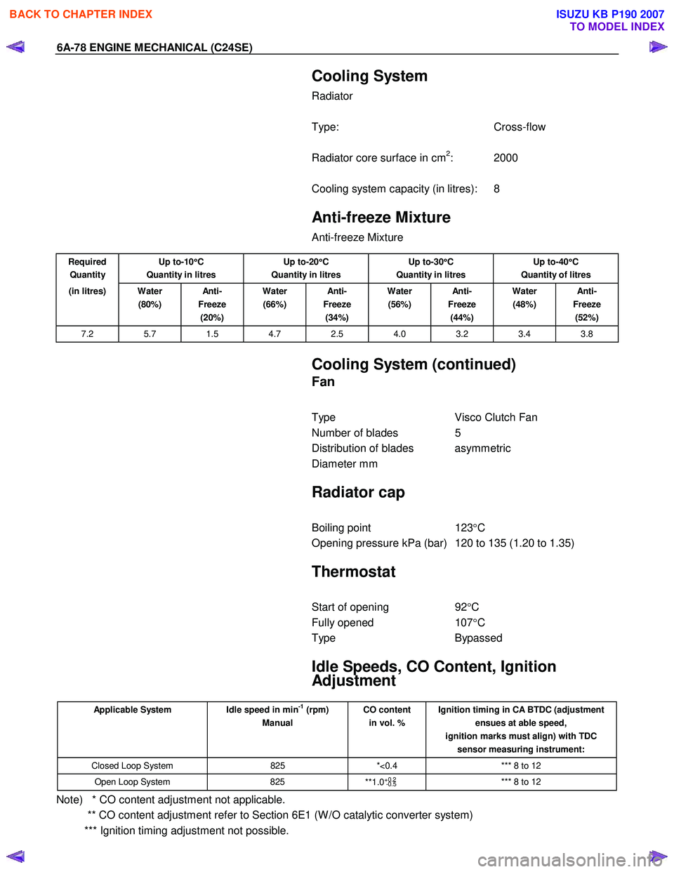
Cooling System
Radiator
Type: Cross-flow
Radiator core surface in cm
2: 2000
Cooling system capacity (in litres): 8
Anti-freeze Mixture
Anti-freeze Mixture
Required
Quantity Up to-10
°
°°
°
C
Quantity in litres Up to-20
°
°°
°
C
Quantity in litres Up to-30
°
°°
°
C
Quantity in litres Up to-40
°
°°
°
C
Quantity of litres
(in litres) Water (80%) An ti -
Freeze (20%) Water
(66%) An ti -
Freeze (34%) Water
(56%) An ti -
Freeze (44%) Water
(48%) An ti -
Freeze (52%)
7.2 5.7 1.5 4.7 2.5 4.0 3.2 3.4 3.8
Cooling System (continued)
Fan
Type Visco Clutch Fan
Number of blades 5
Distribution of blades asymmetric
Diameter mm
Radiator cap
Boiling point 123°C
Opening pressure kPa (bar) 120 to 135 (1.20 to 1.35)
Thermostat
Start of opening 92°C
Fully opened 107°C
Type Bypassed
Idle Speeds, CO Content, Ignition
Adjustment
Applicable System Idle speed in min-1 (rpm)
Manual CO content
in vol. % Ignition timing in CA BTDC (adjustment
ensues at able speed,
ignition marks must align) with TDC sensor measuring instrument:
Closed Loop System 825 *<0.4 *** 8 to 12
Open Loop System 825
**1.0+0.2
-0.5 *** 8 to 12
Note) * CO content adjustment not applicable.
** CO content adjustment refer to Section 6E1 (W /O catalytic converter system)
*** Ignition timing adjustment not possible.
BACK TO CHAPTER INDEX
TO MODEL INDEX
ISUZU KB P190 2007
Page 2105 of 6020
ENGINE COOLING 6B-1
SECTION 6B
ENGINE COOLING
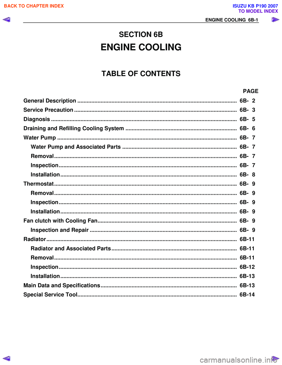
TABLE OF CONTENTS
PAGE
General Description ....................................................................................................... 6B- 2
Service Precaution ......................................................................................................... 6B- 3
Diagnosis ...................................................................................................................... .. 6B- 5
Draining and Refilling Cooling System ........................................................................ 6B- 6
Water Pump .................................................................................................................... 6B- 7
Water Pump and Associated Parts .......................................................................... 6B- 7
Removal ...................................................................................................................... 6 B- 7
Inspection ................................................................................................................... 6 B- 7
Installation .................................................................................................................. 6B- 8
Thermostat ..................................................................................................................... . 6B- 9
Removal ...................................................................................................................... 6 B- 9
Inspection ................................................................................................................... 6 B- 9
Installation .................................................................................................................. 6B- 9
Fan clutch with Cooling Fan.......................................................................................... 6B- 9 Inspection and Repair ............................................................................................... 6B- 9
Radiator ....................................................................................................................... .... 6B-11
Radiator and Associated Parts ................................................................................. 6B-11
Removal ...................................................................................................................... 6 B-11
Inspection ................................................................................................................... 6 B-12
Installation .................................................................................................................. 6B-13
Main Data and Specifications ........................................................................................ 6B-13
Special Service Tool....................................................................................................... 6B- 14
BACK TO CHAPTER INDEX
TO MODEL INDEX
ISUZU KB P190 2007
Page 2106 of 6020
6B-2 ENGINE COOLING
General Description
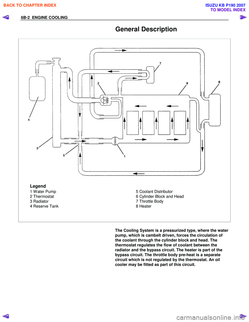
Legend
1 W ater Pump
2 Thermostat
3 Radiator
4 Reserve Tank 5 Coolant Distributor
6 Cylinder Block and Head
7 Throttle Body
8 Heater
The Cooling System is a pressurized type, where the water
pump, which is cambelt driven, forces the circulation of
the coolant through the cylinder block and head. The
thermostat regulates the flow of coolant between the
radiator and the bypass circuit. The heater is part of the
bypass circuit. The throttle body pre-heat is a separate
circuit which is not regulated by the thermostat. An oil
cooler may be fitted as part of this circuit.
BACK TO CHAPTER INDEX
TO MODEL INDEX
ISUZU KB P190 2007
Page 2107 of 6020
ENGINE COOLING 6B-3
Service Precaution
CAUTION:
Always use the correct fastener in the proper location.
When you replace a fastener, use ONLY the exact part
number for that application. ISUZU will call out those
fasteners that require a replacement after removal. ISUZU
will also call out the fasteners that require thread lockers
or thread sealant. UNLESS OTHERWISE SPECIFIED, do
not use supplemental coatings (Paints, greases, or other
corrosion inhibitors) on threaded fasteners or fastener
joint interfaces. Generally, such coatings adversely affect
the fastener torque and the joint clamping force, and may
damage the fastener. When you install fasteners, use the
correct tightening sequence and specifications. Following
these instructions can help you avoid damage to parts
and systems.
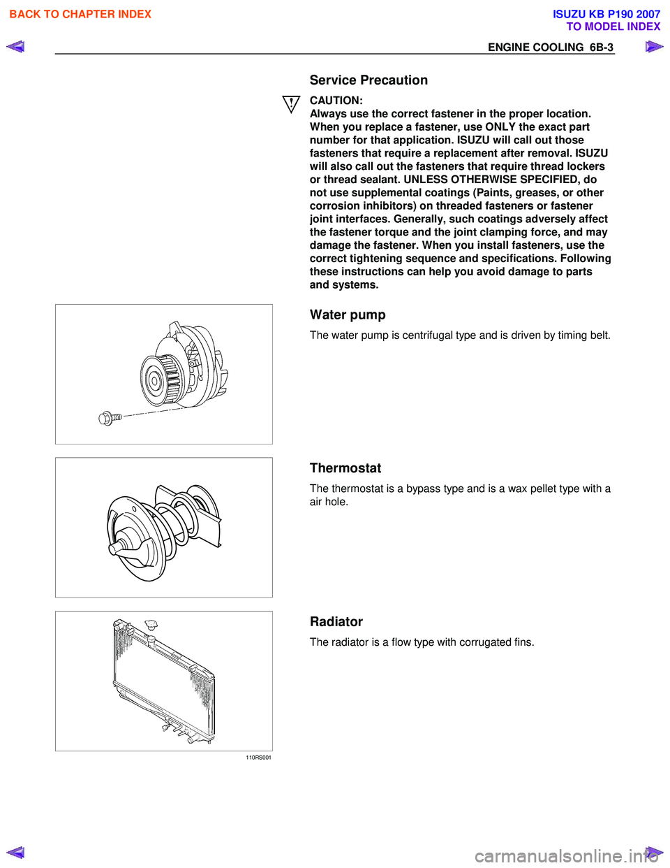
Water pump
The water pump is centrifugal type and is driven by timing belt.
Thermostat
The thermostat is a bypass type and is a wax pellet type with a
air hole.
110RS001
Radiator
The radiator is a flow type with corrugated fins.
BACK TO CHAPTER INDEX
TO MODEL INDEX
ISUZU KB P190 2007
Page 2109 of 6020
ENGINE COOLING 6B-5
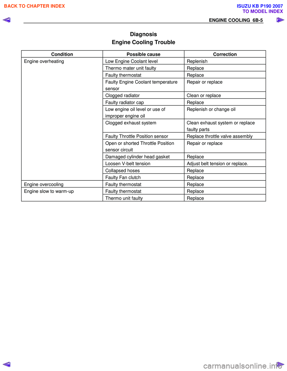
Diagnosis
Engine Cooling Trouble
Condition Possible cause Correction
Engine overheating Low Engine Coolant level Replenish
Thermo mater unit faulty Replace
Faulty thermostat Replace
Faulty Engine Coolant temperature
sensor Repair or replace
Clogged radiator Clean or replace
Faulty radiator cap Replace
Low engine oil level or use of
improper engine oil Replenish or change oil
Clogged exhaust system Clean exhaust system or replace
faulty parts
Faulty Throttle Position sensor Replace throttle valve assembly
Open or shorted Throttle Position
sensor circuit Repair or replace
Damaged cylinder head gasket Replace
Loosen V-belt tension Adjust belt tension or replace.
Collapsed hoses Replace
Faulty Fan clutch Replace
Engine overcooling Faulty thermostat Replace
Engine slow to warm-up Faulty thermostat Replace
Thermo unit faulty Replace
BACK TO CHAPTER INDEX
TO MODEL INDEX
ISUZU KB P190 2007