2007 ISUZU KB P190 radiator
[x] Cancel search: radiatorPage 1283 of 6020
Engine Control System (4JH1) 6E-249
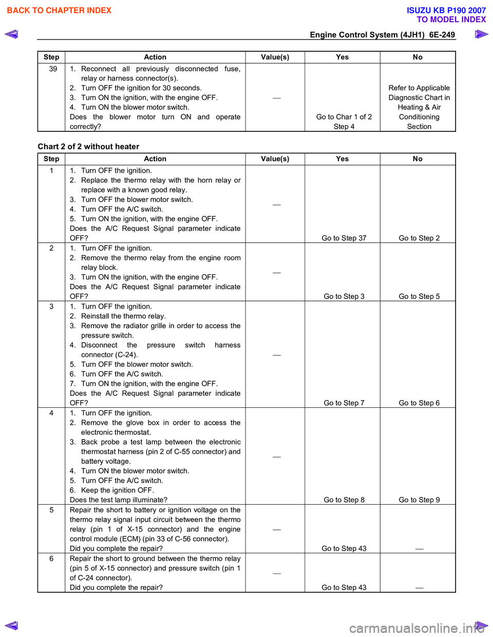
Step Action Value(s) Yes No
39 1. Reconnect all previously disconnected fuse,
relay or harness connector(s).
2. Turn OFF the ignition for 30 seconds.
3. Turn ON the ignition, with the engine OFF.
4. Turn ON the blower motor switch.
Does the blower motor turn ON and operate
correctly?
Go to Char 1 of 2 Step 4 Refer to Applicable
Diagnostic Chart in Heating & Air Conditioning Section
Chart 2 of 2 without heater
Step Action Value(s) Yes No
1 1. Turn OFF the ignition.
2. Replace the thermo relay with the horn relay or replace with a known good relay.
3. Turn OFF the blower motor switch.
4. Turn OFF the A/C switch.
5. Turn ON the ignition, with the engine OFF.
Does the A/C Request Signal parameter indicate
OFF?
Go to Step 37 Go to Step 2
2 1. Turn OFF the ignition. 2. Remove the thermo relay from the engine room relay block.
3. Turn ON the ignition, with the engine OFF.
Does the A/C Request Signal parameter indicate
OFF?
Go to Step 3 Go to Step 5
3 1. Turn OFF the ignition. 2. Reinstall the thermo relay.
3. Remove the radiator grille in order to access the pressure switch.
4. Disconnect the pressure switch harness connector (C-24).
5. Turn OFF the blower motor switch.
6. Turn OFF the A/C switch.
7. Turn ON the ignition, with the engine OFF.
Does the A/C Request Signal parameter indicate
OFF?
Go to Step 7 Go to Step 6
4 1. Turn OFF the ignition. 2. Remove the glove box in order to access the electronic thermostat.
3. Back probe a test lamp between the electronic thermostat harness (pin 2 of C-55 connector) and
battery voltage.
4. Turn ON the blower motor switch.
5. Turn OFF the A/C switch.
6. Keep the ignition OFF.
Does the test lamp illuminate?
Go to Step 8 Go to Step 9
5 Repair the short to battery or ignition voltage on the thermo relay signal input circuit between the thermo
relay (pin 1 of X-15 connector) and the engine
control module (ECM) (pin 33 of C-56 connector).
Did you complete the repair?
Go to Step 43
6 Repair the short to ground between the thermo relay
(pin 5 of X-15 connector) and pressure switch (pin 1
of C-24 connector).
Did you complete the repair?
Go to Step 43
BACK TO CHAPTER INDEX
TO MODEL INDEX
ISUZU KB P190 2007
Page 1284 of 6020
6E-250 Engine Control System (4JH1)
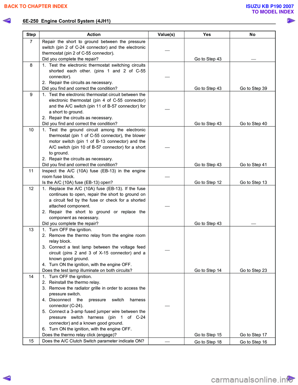
Step Action Value(s) Yes No
7 Repair the short to ground between the pressure
switch (pin 2 of C-24 connector) and the electronic
thermostat (pin 2 of C-55 connector).
Did you complete the repair?
Go to Step 43
8 1. Test the electronic thermostat switching circuits
shorted each other. (pins 1 and 2 of C-55
connector).
2. Repair the circuits as necessary.
Did you find and correct the condition?
Go to Step 43 Go to Step 39
9 1. Test the electronic thermostat circuit between the electronic thermostat (pin 4 of C-55 connector)
and the A/C switch (pin 11 of B-57 connector) for
a short to ground.
2. Repair the circuits as necessary.
Did you find and correct the condition?
Go to Step 43 Go to Step 40
10 1. Test the ground circuit among the electronic thermostat (pin 1 of C-55 connector), the blower
motor switch (pin 1 of B-13 connector) and the
A/C switch (pin 10 of B-57 connector) for a short
to ground.
2. Repair the circuits as necessary.
Did you find and correct the condition?
Go to Step 43 Go to Step 41
11 Inspect the A/C (10A) fuse (EB-13) in the engine room fuse block.
Is the A/C (10A) fuse (EB-13) open?
Go to Step 12 Go to Step 13
12 1. Replace the A/C (10A) fuse (EB-13). If the fuse continues to open, repair the short to ground on
a circuit fed by the fuse or check for a shorted
attached component.
2. Repair the short to ground or replace the component as necessary.
Did you complete the repair?
Go to Step 43
13 1. Turn OFF the ignition.
2. Remove the thermo relay from the engine room relay block.
3. Connect a test lamp between the voltage feed circuit (pins 2 and 3 of X-15 connector) and a
known good ground.
4. Turn ON the ignition, with the engine OFF.
Does the test lamp illuminate on both circuits?
Go to Step 14 Go to Step 23
14 1. Turn OFF the ignition. 2. Reinstall the thermo relay.
3. Remove the radiator grille in order to access the pressure switch.
4. Disconnect the pressure switch harness connector (C-24).
5. Connect a 3-amp fused jumper wire between the pressure switch harness (pin 1 of C-24
connector) and a known good ground.
6. Turn ON the ignition, with the engine OFF.
Does the thermo relay click (engage)?
Go to Step 15 Go to Step 17
15 Does the A/C Clutch Switch parameter indicate ON?
Go to Step 18 Go to Step 16
BACK TO CHAPTER INDEX
TO MODEL INDEX
ISUZU KB P190 2007
Page 1332 of 6020
6E-298 Engine Control System (4JH1)
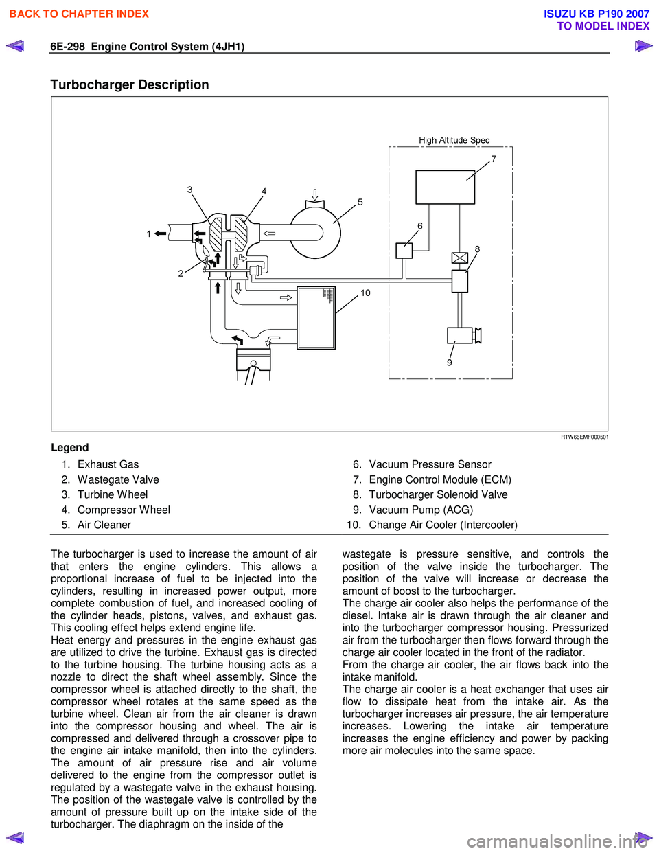
Turbocharger Description
RTW 66EMF000501
Legend
1. Exhaust Gas
2. W astegate Valve
3. Turbine W heel
4. Compressor W heel
5. Air Cleaner
6. Vacuum Pressure Sensor
7. Engine Control Module (ECM)
8. Turbocharger Solenoid Valve
9. Vacuum Pump (ACG)
10. Change Air Cooler (Intercooler)
The turbocharger is used to increase the amount of ai
r
that enters the engine cylinders. This allows a
proportional increase of fuel to be injected into the
cylinders, resulting in increased power output, more
complete combustion of fuel, and increased cooling o
f
the cylinder heads, pistons, valves, and exhaust gas.
This cooling effect helps extend engine life.
Heat energy and pressures in the engine exhaust gas
are utilized to drive the turbine. Exhaust gas is directed
to the turbine housing. The turbine housing acts as a
nozzle to direct the shaft wheel assembly. Since the
compressor wheel is attached directly to the shaft, the
compressor wheel rotates at the same speed as the
turbine wheel. Clean air from the air cleaner is drawn
into the compressor housing and wheel. The air is
compressed and delivered through a crossover pipe to
the engine air intake manifold, then into the cylinders.
The amount of air pressure rise and air volume
delivered to the engine from the compressor outlet is
regulated by a wastegate valve in the exhaust housing.
The position of the wastegate valve is controlled by the
amount of pressure built up on the intake side of the
turbocharger. The diaphragm on the inside of the
wastegate is pressure sensitive, and controls the
position of the valve inside the turbocharger. The
position of the valve will increase or decrease the
amount of boost to the turbocharger.
The charge air cooler also helps the performance of the
diesel. Intake air is drawn through the air cleaner and
into the turbocharger compressor housing. Pressurized
air from the turbocharger then flows forward through the
charge air cooler located in the front of the radiator.
From the charge air cooler, the air flows back into the
intake manifold.
The charge air cooler is a heat exchanger that uses ai
r
flow to dissipate heat from the intake air. As the
turbocharger increases air pressure, the air temperature
increases. Lowering the intake air temperature
increases the engine efficiency and power by packing
more air molecules into the same space.
BACK TO CHAPTER INDEX
TO MODEL INDEX
ISUZU KB P190 2007
Page 1373 of 6020
ENGINE MECHANICAL (4JK1/4JJ1) 6A-13
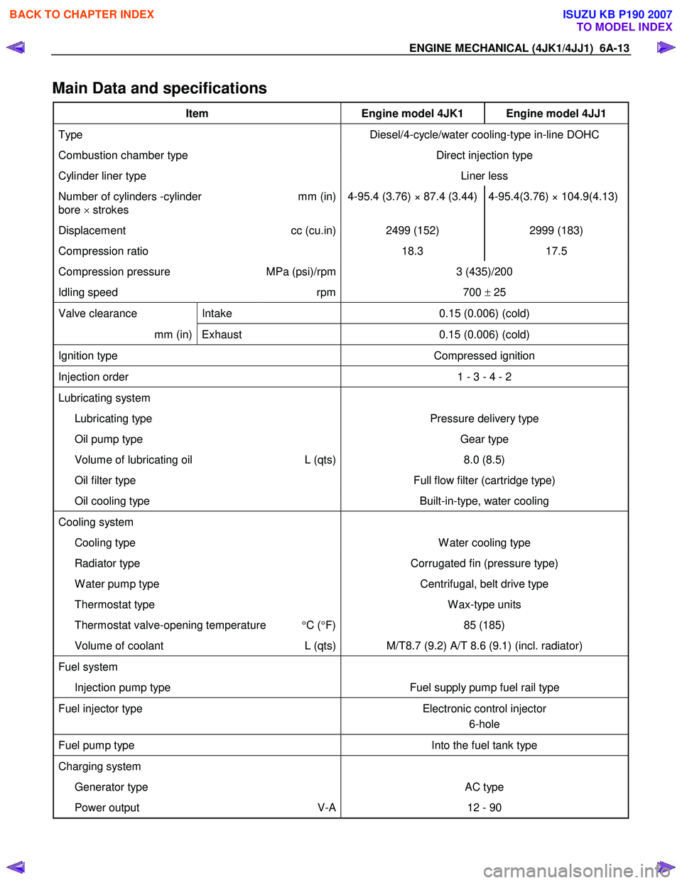
Main Data and specifications
Item Engine model 4JK1 Engine model 4JJ1
Type Diesel/4-cycle/water cooling-type in-line DOHC
Combustion chamber type Direct injection type
Cylinder liner type Liner less
Number of cylinders -cylinder
bore × strokes mm (in) 4-95.4 (3.76) × 87.4 (3.44) 4-95.4(3.76) × 104.9(4.13)
Displacement
cc (cu.in) 2499 (152) 2999 (183)
Compression ratio 18.3 17.5
Compression pressure MPa (psi)/rpm 3 (435)/200
Idling speed rpm 700 ± 25
Valve clearance Intake 0.15 (0.006) (cold)
mm (in) Exhaust 0.15 (0.006) (cold)
Ignition type Compressed ignition
Injection order 1 - 3 - 4 - 2
Lubricating system
Lubricating type Pressure delivery type
Oil pump type Gear type
Volume of lubricating oil L (qts) 8.0 (8.5)
Oil filter type Full flow filter (cartridge type)
Oil cooling type Built-in-type, water cooling
Cooling system
Cooling type W ater cooling type
Radiator type Corrugated fin (pressure type)
W ater pump type Centrifugal, belt drive type
Thermostat type W ax-type units
Thermostat valve-opening temperature °C ( °F) 85 (185)
Volume of coolant L (qts) M/T8.7 (9.2) A/T 8.6 (9.1) (incl. radiator)
Fuel system
Injection pump type Fuel supply pump fuel rail type
Fuel injector type Electronic control injector
6-hole
Fuel pump type Into the fuel tank type
Charging system
Generator type AC type
Power output V-A 12 - 90
BACK TO CHAPTER INDEX
TO MODEL INDEX
ISUZU KB P190 2007
Page 1375 of 6020
ENGINE MECHANICAL (4JK1/4JJ1) 6A-15
Engine Assembly
Removal
1. Disconnect the negative battery cable.
2. Remove the engine hood.
3. Drain the coolant.
4. Remove the starter motor.
5. Remove the transmission assembly.
Refer to removal procedure for “TRANSMISSION” in this manual.
6. Disconnect the ECM harness connector.
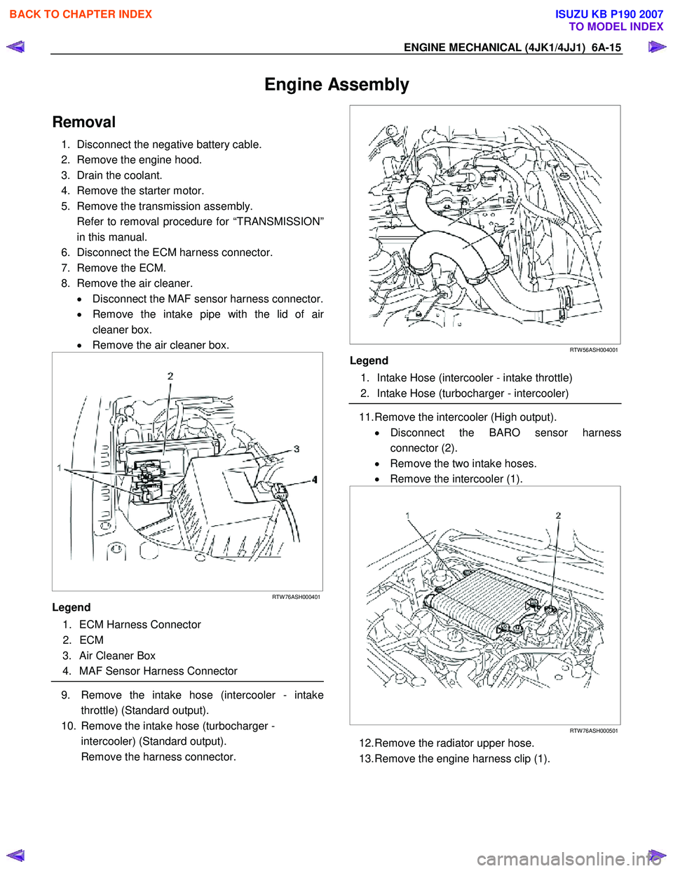
7. Remove the ECM.
8. Remove the air cleaner. • Disconnect the MAF sensor harness connector.
• Remove the intake pipe with the lid of ai
r
cleaner box.
• Remove the air cleaner box.
RTW 76ASH000401
Legend
1. ECM Harness Connector
2. ECM
3. Air Cleaner Box
4. MAF Sensor Harness Connector
9. Remove the intake hose (intercooler - intake
throttle) (Standard output).
10. Remove the intake hose (turbocharger - intercooler) (Standard output).
Remove the harness connector.
RTW 56ASH004001
Legend
1. Intake Hose (intercooler - intake throttle)
2. Intake Hose (turbocharger - intercooler)
11. Remove the intercooler (High output).
• Disconnect the BARO sensor harness
connector (2).
• Remove the two intake hoses.
• Remove the intercooler (1).
RTW 76ASH000501
12. Remove the radiator upper hose.
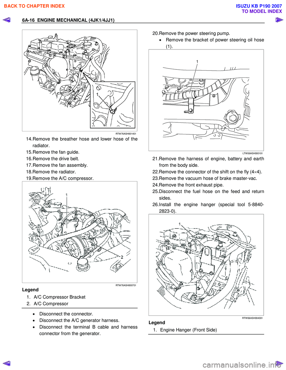
13. Remove the engine harness clip (1).
BACK TO CHAPTER INDEX
TO MODEL INDEX
ISUZU KB P190 2007
Page 1376 of 6020
6A-16 ENGINE MECHANICAL (4JK1/4JJ1)
RTW 76ASH001401
14. Remove the breather hose and lower hose of the
radiator.
15. Remove the fan guide.
16. Remove the drive belt.
17. Remove the fan assembly.
18.Remove the radiator.
19.Remove the A/C compressor.
RTW 76ASH000701
Legend
1. A/C Compressor Bracket
2. A/C Compressor
• Disconnect the connector.
• Disconnect the A/C generator harness.
• Disconnect the terminal B cable and harness
connector from the generator.
20.Remove the power steering pump.
• Remove the bracket of power steering oil hose
(1).
LTW 56ASH000101
21.Remove the harness of engine, battery and earth
from the body side.
22.Remove the connector of the shift on the fly (4 ×4).
23.Remove the vacuum hose of brake master-vac.
24.Remove the front exhaust pipe.
25.Disconnect the fuel hose on the feed and return sides.
26.Install the engine hanger (special tool 5-8840- 2823-0).
RTW 56ASH004301
Legend
1. Engine Hanger (Front Side)
BACK TO CHAPTER INDEX
TO MODEL INDEX
ISUZU KB P190 2007
Page 1377 of 6020
ENGINE MECHANICAL (4JK1/4JJ1) 6A-17
RTW 56ASH004401
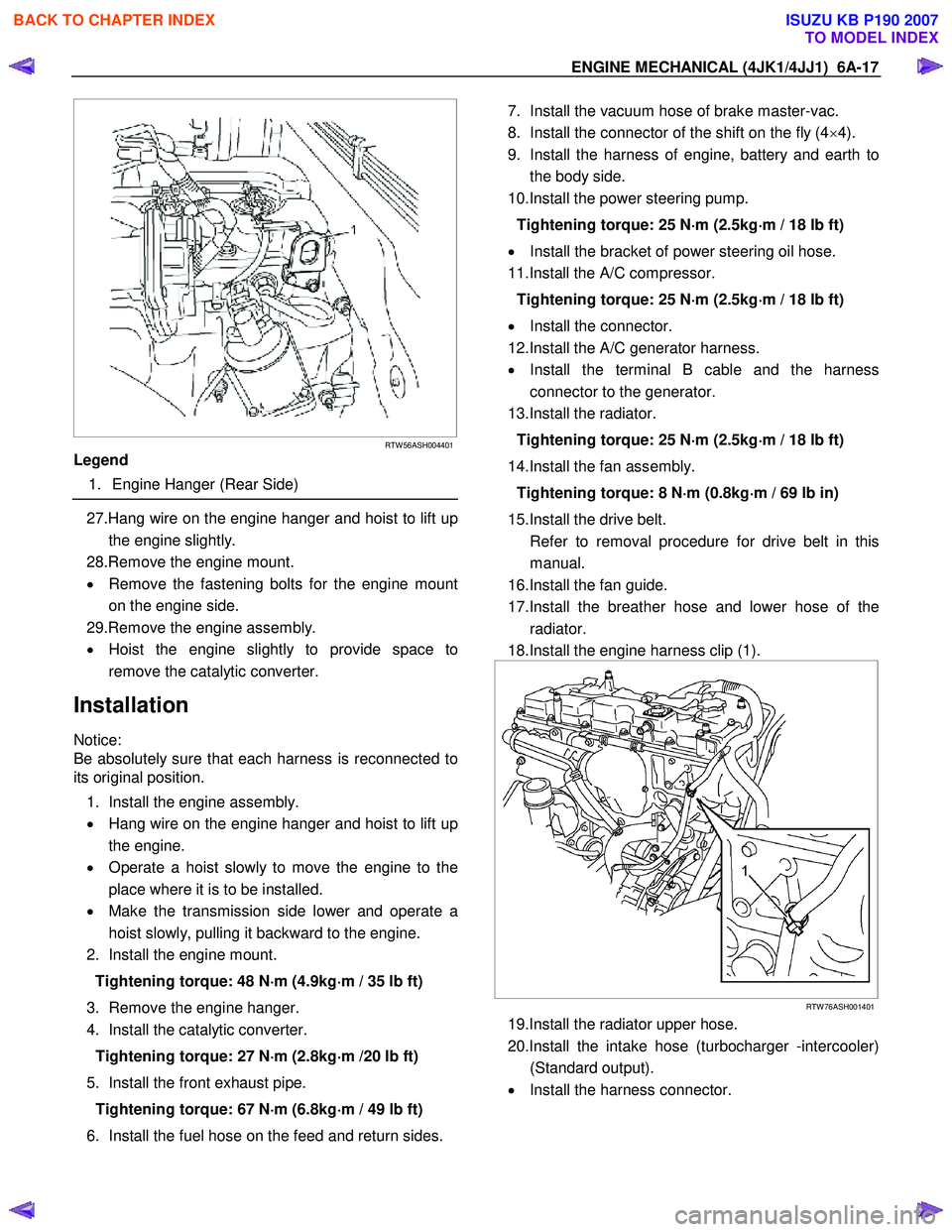
Legend
1. Engine Hanger (Rear Side)
27.Hang wire on the engine hanger and hoist to lift up
the engine slightly.
28.Remove the engine mount.
• Remove the fastening bolts for the engine mount
on the engine side.
29.Remove the engine assembly.
• Hoist the engine slightly to provide space to
remove the catalytic converter.
Installation
Notice:
Be absolutely sure that each harness is reconnected to
its original position.
1. Install the engine assembly.
• Hang wire on the engine hanger and hoist to lift up
the engine.
• Operate a hoist slowly to move the engine to the
place where it is to be installed.
• Make the transmission side lower and operate a
hoist slowly, pulling it backward to the engine.
2. Install the engine mount.
Tightening torque: 48 N ⋅
⋅⋅
⋅
m (4.9kg ⋅
⋅⋅
⋅
m / 35 lb ft)
3. Remove the engine hanger.
4. Install the catalytic converter.
Tightening torque: 27 N ⋅
⋅⋅
⋅
m (2.8kg ⋅
⋅⋅
⋅
m /20 lb ft)
5. Install the front exhaust pipe. Tightening torque: 67 N ⋅
⋅⋅
⋅
m (6.8kg ⋅
⋅⋅
⋅
m / 49 lb ft)
6. Install the fuel hose on the feed and return sides.
7. Install the vacuum hose of brake master-vac.
8. Install the connector of the shift on the fly (4 ×4).
9. Install the harness of engine, battery and earth to the body side.
10.Install the power steering pump.
Tightening torque: 25 N ⋅
⋅⋅
⋅
m (2.5kg ⋅
⋅⋅
⋅
m / 18 lb ft)
• Install the bracket of power steering oil hose.
11.Install the A/C compressor.
Tightening torque: 25 N ⋅
⋅⋅
⋅
m (2.5kg ⋅
⋅⋅
⋅
m / 18 lb ft)
• Install the connector.
12.Install the A/C generator harness.
• Install the terminal B cable and the harness
connector to the generator.
13.Install the radiator.
Tightening torque: 25 N ⋅
⋅⋅
⋅
m (2.5kg ⋅
⋅⋅
⋅
m / 18 lb ft)
14.Install the fan assembly. Tightening torque: 8 N ⋅
⋅⋅
⋅
m (0.8kg ⋅
⋅⋅
⋅
m / 69 lb in)
15.Install the drive belt.
Refer to removal procedure for drive belt in this manual.
16.Install the fan guide.
17.Install the breather hose and lower hose of the radiator.
18.Install the engine harness clip (1).
RTW 76ASH001401
19.Install the radiator upper hose.
20.Install the intake hose (turbocharger -intercooler) (Standard output).
• Install the harness connector.
BACK TO CHAPTER INDEX
TO MODEL INDEX
ISUZU KB P190 2007
Page 1394 of 6020
6A-34 ENGINE MECHANICAL (4JK1/4JJ1)
Removal
1. Loosen the radiator drain plug to drain coolant.
2. Remove the engine cover.
3. Remove the intake hose from the intercooler and intake throttle.
4. Remove the intake hose from the turbocharge
r
and the intercooler.
5. Remove the air intake duct from the turbocharge
r
and the air cleaner.
6. Remove the EGR cooler.
Refer to “EGR Cooler” in EXHAUST SYSTEM Section.
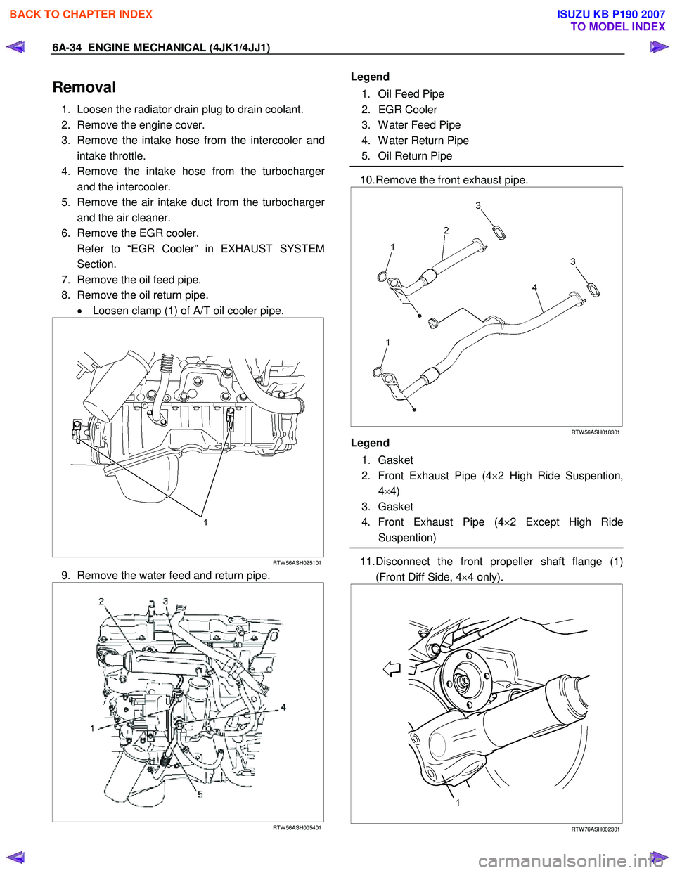
7. Remove the oil feed pipe.
8. Remove the oil return pipe. • Loosen clamp (1) of A/T oil cooler pipe.
RTW 56ASH025101
9. Remove the water feed and return pipe.
RTW 56ASH005401
Legend
1. Oil Feed Pipe
2. EGR Cooler
3. W ater Feed Pipe
4. W ater Return Pipe
5. Oil Return Pipe
10. Remove the front exhaust pipe.
RTW 56ASH018301
Legend
1. Gasket
2. Front Exhaust Pipe (4 ×2 High Ride Suspention,
4 ×4)
3. Gasket
4. Front Exhaust Pipe (4 ×2 Except High Ride
Suspention)
11. Disconnect the front propeller shaft flange (1)
(Front Diff Side, 4 ×4 only).
RTW 76ASH002301
BACK TO CHAPTER INDEX
TO MODEL INDEX
ISUZU KB P190 2007