2007 ISUZU KB P190 SECURITY
[x] Cancel search: SECURITYPage 4424 of 6020
7A2-140 TRANSMISSION CONTROL SYSTEM (JR405E)
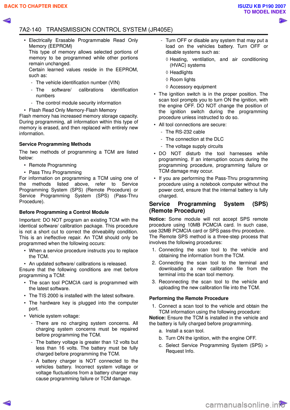
• Electrically Erasable Programmable Read OnlyMemory (EEPROM)
This type of memory allows selected portions of
memory to be programmed while other portions
remain unchanged.
Certain learned values reside in the EEPROM,
such as:
- The vehicle identification number (VIN)
- The software/ calibrations identification numbers
- The control module security information
• Flash Read Only Memory-Flash Memory
Flash memory has increased memory storage capacity.
During programming, all information within this type of
memory is erased, and then replaced with entirely new
information.
Service Programming Methods
The two methods of programming a TCM are listed
below:
• Remote Programming
• Pass Thru Programming
For information on programming a TCM using one of
the methods listed above, refer to Service
Programming System (SPS) (Remote Procedure) or
Service Programming System (SPS) (Pass-Thru
Procedure).
Before Programming a Control Module
Important: DO NOT program an existing TCM with the
identical software/ calibration package. This procedure
is not a short cut to correct the driveability condition.
This is an ineffective repair. An TCM should only be
programmed when the following occurs:
• When a service procedure instructs you to replace the TCM.
• An updated software/ calibrations is released.
Ensure that the following conditions are met before
programming a TCM:
• The scan tool PCMCIA card is programmed with the latest software.
• The TIS 2000 is installed with the latest software.
• The hardware key is plugged into the computer port.
• Vehicle system voltage:
- There are no charging system concerns. Allcharging system concerns must be repaired
before programming the TCM.
- The battery voltage is greater than 12 volts but less than 16 volts. The battery must be fully
charged before programming the TCM.
- A battery charger is NOT connected to the vehicles battery. Incorrect system voltage or
voltage fluctuations from a battery charger may
cause programming failure or TCM damage. - Turn OFF or disable any system that may put a
load on the vehicles battery. Turn OFF or
disable systems such as:
◊ Heating, ventilation, and air conditioning
(HVAC) systems
◊ Headlights
◊ Room lights
◊ Accessory equipment
• The ignition switch is in the proper position. The scan tool prompts you to turn ON the ignition, with
the engine OFF. DO NOT change the position of
the ignition switch during the programming
procedure unless instructed to do so.
• All tool connections are secure:
- The RS-232 cable
- The connection at the DLC
- The voltage supply circuits
• DO NOT disturb the tool harnesses while programming. If an interruption occurs during the
programming procedure, programming failure or
TCM damage may occur.
• If you are performing the Pass-Thru programming procedure using a notebook computer without the
power cord, ensure that the internal battery is fully
charged.
Service Programming System (SPS)
(Remote Procedure)
Notice: Some module will not accept SPS remote
procedure using 10MB PCMCIA card. In such case,
use 32MB PCMCIA card or SPS pass-thru procedure.
The Remote SPS method is a three-step process that
involves the following procedures:
1. Connecting the scan tool to the vehicle and obtaining the information from the TCM.
2. Connecting the scan tool to the terminal and downloading a new calibration file from the
terminal into the scan tool memory.
3. Reconnecting the scan tool to the vehicle and uploading the new calibration file into the TCM.
Performing the Remote Procedure 1. Connect a scan tool to the vehicle and obtain the TCM information using the following procedure:
Notice: Ensure the TCM is installed in the vehicle and
the battery is fully charged before programming.
a. Install a scan tool.
b. Turn ON the ignition, with the engine OFF.
c. Select Service Programming System (SPS) > Request Info.
BACK TO CHAPTER INDEX
TO MODEL INDEX
ISUZU KB P190 2007
Page 5476 of 6020
8A-538 ELECTRICAL-BODY AND CHASSIS
TROUBLESHOOTING
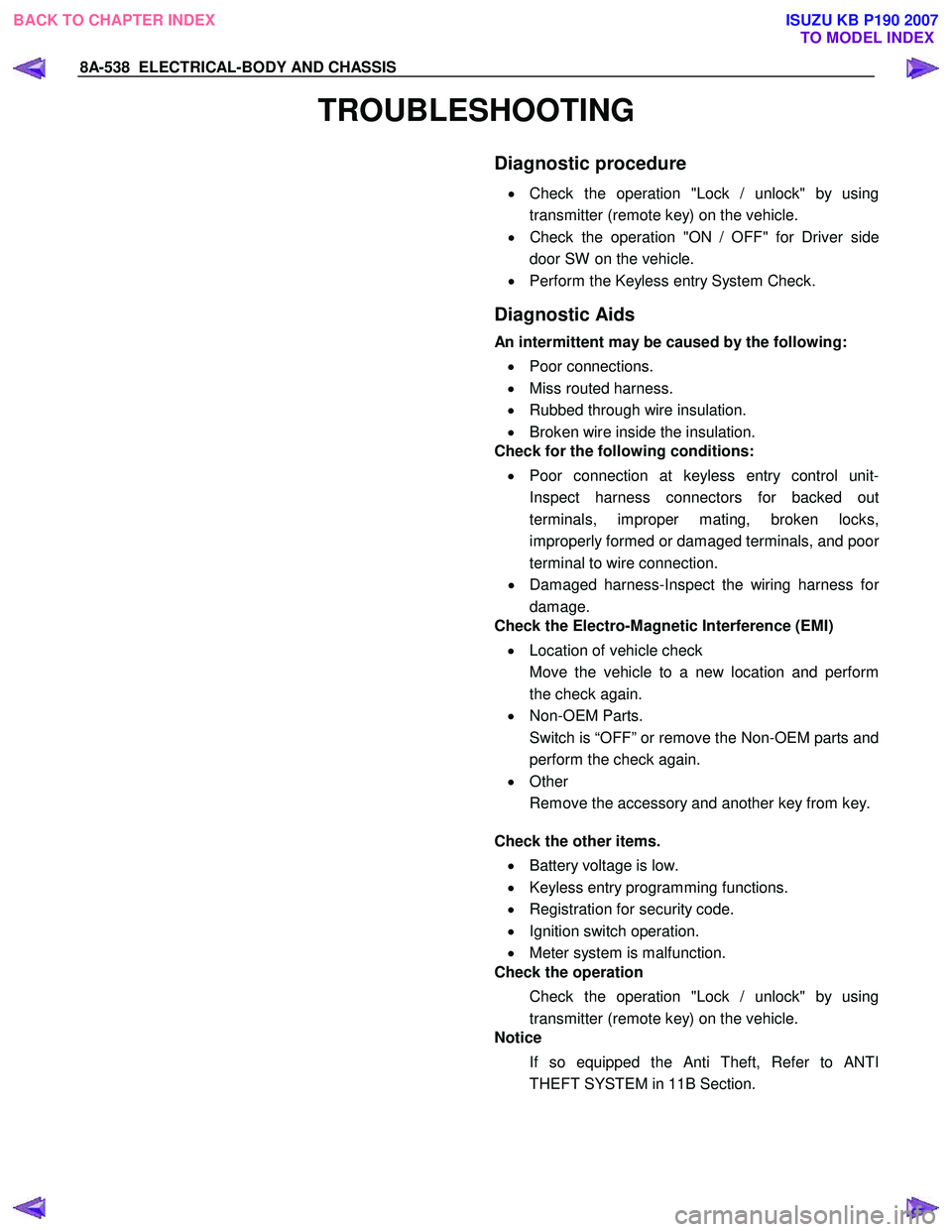
Diagnostic procedure
•
Check the operation "Lock / unlock" by using
transmitter (remote key) on the vehicle.
• Check the operation "ON / OFF" for Driver side
door SW on the vehicle.
• Perform the Keyless entry System Check.
Diagnostic Aids
An intermittent may be caused by the following:
• Poor connections.
• Miss routed harness.
• Rubbed through wire insulation.
• Broken wire inside the insulation.
Check for the following conditions:
• Poor connection at keyless entry control unit-
Inspect harness connectors for backed out
terminals, improper mating, broken locks,
improperly formed or damaged terminals, and poo
r
terminal to wire connection.
• Damaged harness-Inspect the wiring harness fo
r
damage.
Check the Electro-Magnetic Interference (EMI)
• Location of vehicle check
Move the vehicle to a new location and perform
the check again.
• Non-OEM Parts.
Switch is “OFF” or remove the Non-OEM parts and
perform the check again.
• Other
Remove the accessory and another key from key.
Check the other items.
• Battery voltage is low.
• Keyless entry programming functions.
• Registration for security code.
• Ignition switch operation.
• Meter system is malfunction.
Check the operation
Check the operation "Lock / unlock" by using
transmitter (remote key) on the vehicle.
Notice
If so equipped the Anti Theft, Refer to ANTI
THEFT SYSTEM in 11B Section.
BACK TO CHAPTER INDEX TO MODEL INDEXISUZU KB P190 2007
Page 5478 of 6020
8A-540 ELECTRICAL-BODY AND CHASSIS
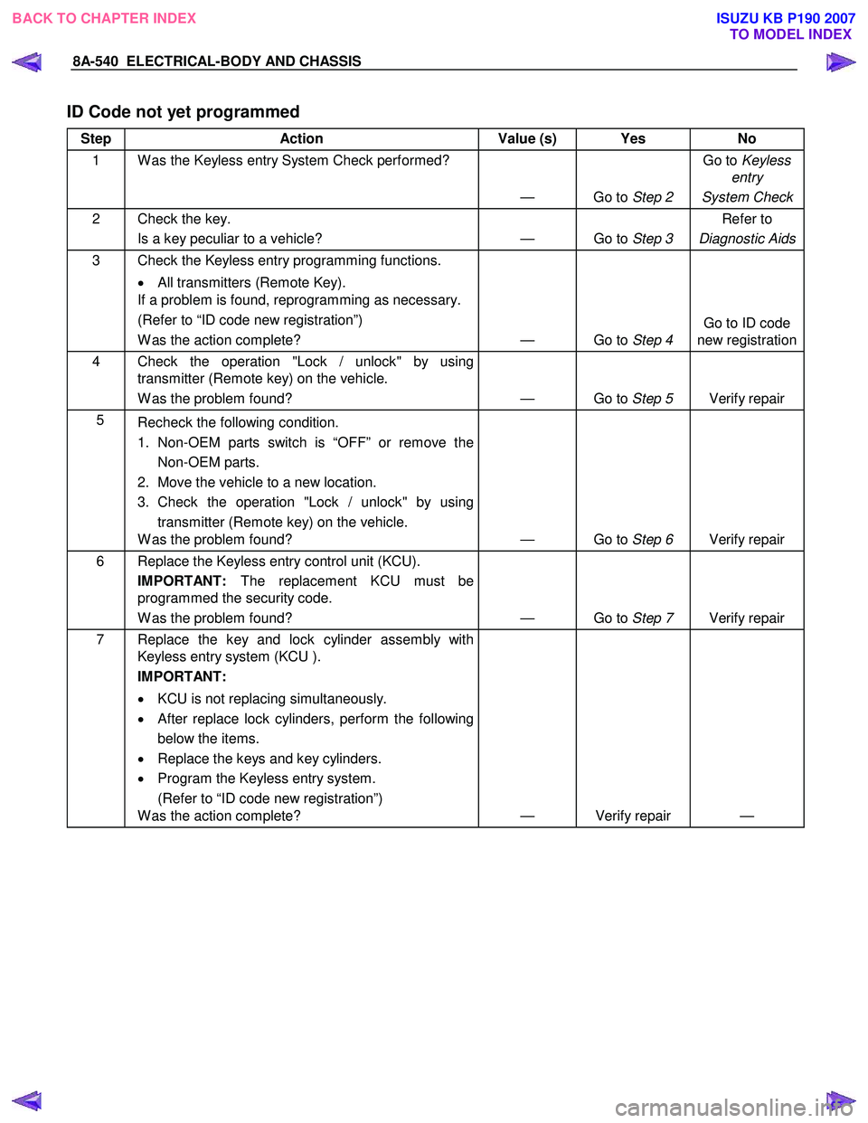
ID Code not yet programmed
Step Action Value (s) Yes No
1 W as the Keyless entry System Check performed?
— Go to Step 2 Go to
Keyless
entry
System Check
2 Check the key. Is a key peculiar to a vehicle? — Go to Step 3 Refer to
Diagnostic Aids
3 Check the Keyless entry programming functions.
• All transmitters (Remote Key).
If a problem is found, reprogramming as necessary.
(Refer to “ID code new registration”)
W as the action complete? — Go to Step 4 Go to ID code
new registration
4 Check the operation "Lock / unlock" by using transmitter (Remote key) on the vehicle.
W as the problem found? — Go to Step 5 Verify repair
5
Recheck the following condition.
1. Non-OEM parts switch is “OFF” or remove the Non-OEM parts.
2. Move the vehicle to a new location.
3. Check the operation "Lock / unlock" by using transmitter (Remote key) on the vehicle.
W as the problem found? — Go to Step 6 Verify repair
6 Replace the Keyless entry control unit (KCU).
IMPORTANT: The replacement KCU must be
programmed the security code.
W as the problem found? — Go to Step 7 Verify repair
7 Replace the key and lock cylinder assembly with
Keyless entry system (KCU ).
IMPORTANT:
• KCU is not replacing simultaneously.
• After replace lock cylinders, perform the following
below the items.
• Replace the keys and key cylinders.
• Program the Keyless entry system.
(Refer to “ID code new registration”)
W as the action complete? — Verify repair —
BACK TO CHAPTER INDEX
TO MODEL INDEXISUZU KB P190 2007
Page 5479 of 6020
ELECTRICAL-BODY AND CHASSIS 8A-541
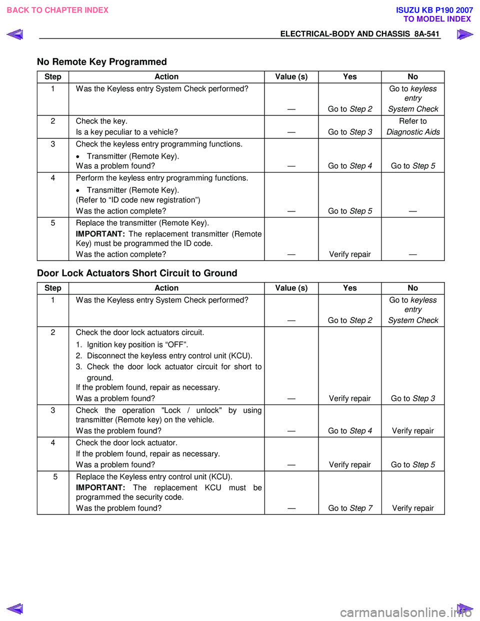
No Remote Key Programmed
Step Action Value (s) Yes No
1 W as the Keyless entry System Check performed?
— Go to Step 2 Go to
keyless
entry
System Check
2 Check the key. Is a key peculiar to a vehicle? — Go to Step 3 Refer to
Diagnostic Aids
3 Check the keyless entry programming functions.
• Transmitter (Remote Key).
W as a problem found? — Go to Step 4 Go to Step 5
4 Perform the keyless entry programming functions.
• Transmitter (Remote Key).
(Refer to “ID code new registration”)
W as the action complete? — Go to Step 5 —
5 Replace the transmitter (Remote Key).
IMPORTANT: The replacement transmitter (Remote
Key) must be programmed the ID code.
W as the action complete? — Verify repair —
Door Lock Actuators Short Circuit to Ground
Step Action Value (s) Yes No
1 W as the Keyless entry System Check performed?
— Go to Step 2 Go to
keyless
entry
System Check
2 Check the door lock actuators circuit.
1. Ignition key position is “OFF”.
2. Disconnect the keyless entry control unit (KCU).
3. Check the door lock actuator circuit for short to ground.
If the problem found, repair as necessary.
W as a problem found? — Verify repair Go to Step 3
3 Check the operation "Lock / unlock" by using
transmitter (Remote key) on the vehicle.
W as the problem found? — Go to Step 4 Verify repair
4 Check the door lock actuator.
If the problem found, repair as necessary.
W as a problem found? — Verify repair Go to Step 5
5 Replace the Keyless entry control unit (KCU).
IMPORTANT: The replacement KCU must be
programmed the security code.
W as the problem found? — Go to Step 7 Verify repair
BACK TO CHAPTER INDEX
TO MODEL INDEXISUZU KB P190 2007
Page 5518 of 6020
8A-580 ELECTRICAL-BODY AND CHASSIS
TECH-2 OPERATION AND PROGRAMING
KEYLESS ENTRY
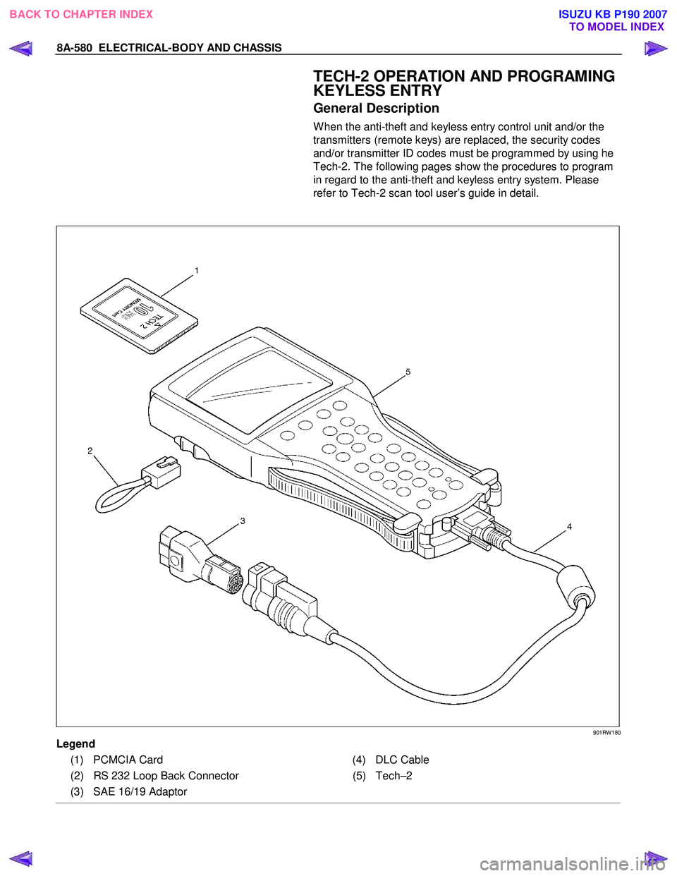
General Description
W hen the anti-theft and keyless entry control unit and/or the
transmitters (remote keys) are replaced, the security codes
and/or transmitter ID codes must be programmed by using he
Tech-2. The following pages show the procedures to program
in regard to the anti-theft and keyless entry system. Please
refer to Tech-2 scan tool user’s guide in detail.
901RW 180
Legend
(1) PCMCIA Card (4) DLC Cable
(2) RS 232 Loop Back Connector (5)Tech–2
(3) SAE 16/19 Adaptor
BACK TO CHAPTER INDEX TO MODEL INDEXISUZU KB P190 2007
Page 5523 of 6020
ELECTRICAL-BODY AND CHASSIS 8A-585
RTW 38DSH001701
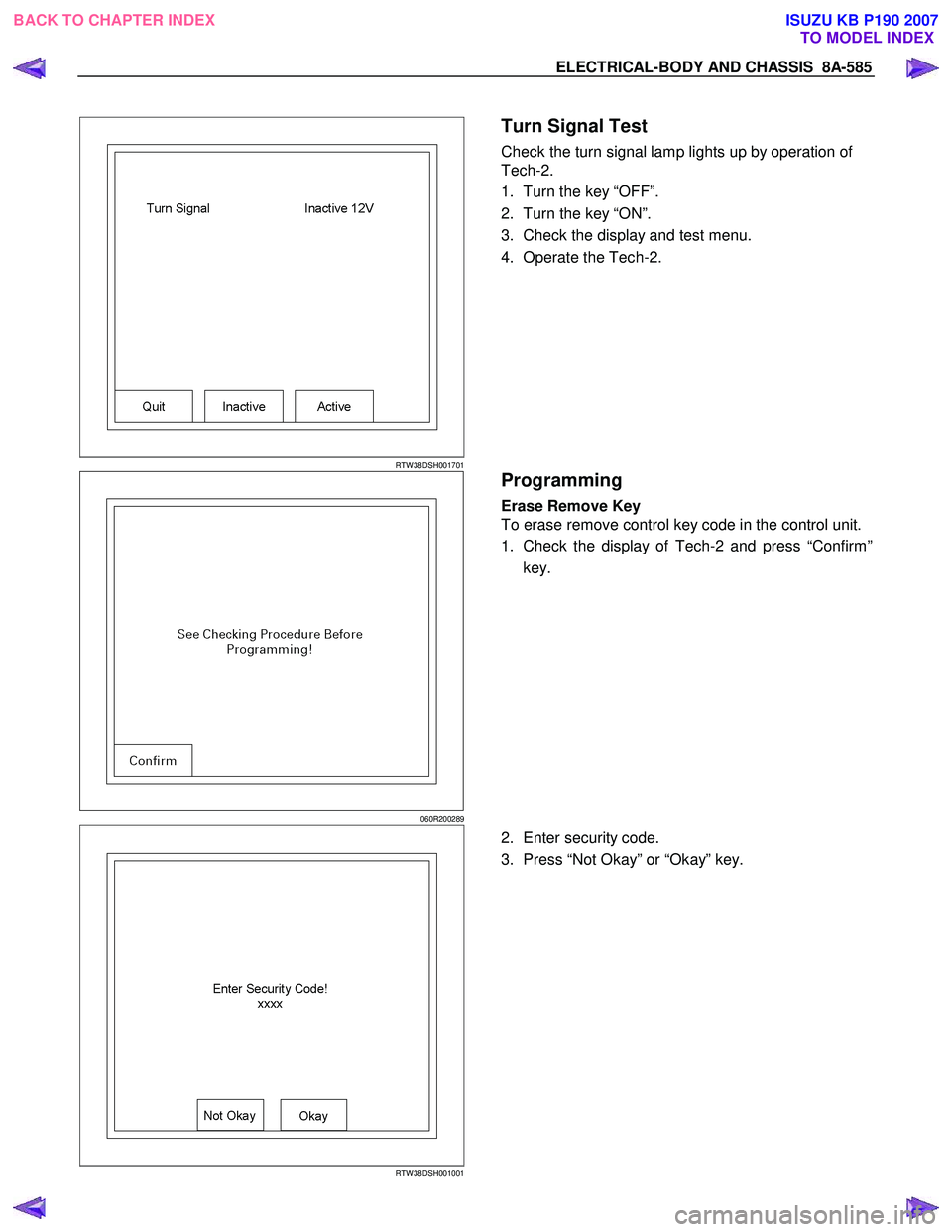
Turn Signal Test
Check the turn signal lamp lights up by operation of
Tech-2.
1. Turn the key “OFF”.
2. Turn the key “ON”.
3. Check the display and test menu.
4. Operate the Tech-2.
060R200289
Programming
Erase Remove Key
To erase remove control key code in the control unit.
1. Check the display of Tech-2 and press “Confirm”
key.
RTW 38DSH001001
2. Enter security code.
3. Press “Not Okay” or “Okay” key.
BACK TO CHAPTER INDEX TO MODEL INDEXISUZU KB P190 2007
Page 5851 of 6020

Immobilizer Control System(4jk1/4jj1/hfv6)...................................................................5962 PAGE
Immobilizer System(C24se,4ja1-t)..................................................................................6010
S ection 11B Antitheft System.........................................................................................6066
SECTION 11
TA BLE OF CONTENTS
SECURITY
SECURITY 11-1
TO MODEL INDEX
BACK TO MAIN INDEX
ISUZU KB P190 2007
Page 5859 of 6020
11A-8 IMMOBILIZER CONTROL SYSTEM (4JK1/4JJ1/HFV6)
Diagnostic Information and Procedures
Diagnostic Starting Point - Immobilizer
Controls
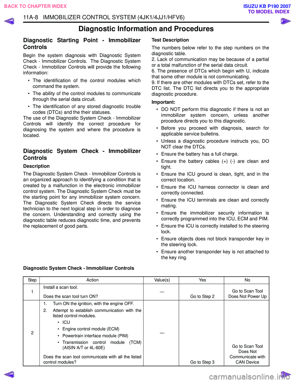
Begin the system diagnosis with Diagnostic System
Check - Immobilizer Controls. The Diagnostic System
Check - Immobilizer Controls will provide the following
information:
• The identification of the control modules which command the system.
• The ability of the control modules to communicate through the serial data circuit.
• The identification of any stored diagnostic trouble codes (DTCs) and the their statuses.
The use of the Diagnostic System Check - Immobilizer
Controls will identify the correct procedure for
diagnosing the system and where the procedure is
located.
Diagnostic System Check - Immobilizer
Controls
Description
The Diagnostic System Check - Immobilizer Controls is
an organized approach to identifying a condition that is
created by a malfunction in the electronic immobilizer
control system. The Diagnostic System Check must be
the starting point for any immobilizer system concern.
The Diagnostic System Check directs the service
technician to the next logical step in order to diagnose
the concern. Understanding and correctly using the
diagnostic table reduces diagnostic time, and prevents
the replacement of good parts. Test Description
The numbers below refer to the step numbers on the
diagnostic table.
2. Lack of communication may be because of a partial
or a total malfunction of the serial data circuit.
6. The presence of DTCs which begin with U, indicate
that some other module is not communicating.
9. If there are other modules with DTCs set, refer to the
DTC list. The DTC list directs you to the appropriate
diagnostic procedure.
Important: • DO NOT perform this diagnostic if there is not an immobilizer system concern, unless another
procedure directs you to this diagnostic.
• Before you proceed with diagnosis, search for applicable service bulletins.
• Unless a diagnostic procedure instructs you, DO NOT clear the DTCs.
• Ensure the battery has a full charge.
• Ensure the battery cables (+) (-) are clean and tight.
• Ensure the ICU ground is clean, tight, and in the correct location.
• Ensure the ICU harness connector is clean and correctly connected.
• Ensure the ICU terminals are clean and correctly mating.
• Ensure the immobilizer security information is correctly programmed into the ICU, ECM and PIM.
• Ensure the ICU is correctly installed to the steering lock.
• Ensure objects does not block transponder key in the steering lock.
• Ensure another transponder key is not attached to the key ring.
Diagnostic System Check - Immobilizer Controls
Step Action Value(s)Yes No
1 Install a scan tool.
Does the scan tool turn ON? —
Go to Step 2 Go to Scan Tool
Does Not Power Up
2 1. Turn ON the ignition, with the engine OFF.
2. Attempt to establish communication with the listed control modules.
•ICU
• Engine control module (ECM)
• Powertrain interface module (PIM)
• Transmission control module (TCM) (AISIN A/T or 4L-60E)
Does the scan tool communicate with all the listed
control modules? —
Go to Step 3 Go to Scan Tool
Does Not
Communicate with CAN Device
BACK TO CHAPTER INDEX TO MODEL INDEX
ISUZU KB P190 2007