Page 2994 of 6020

Engine Mechanical – V6 Page 6A1–217
Page 6A1–217
3.23 Cylinder Head Assembly
Remove
Right-hand Side (Bank 1) Cylinder Head
1 Remove the heater hoses and heater pipe assembly, refer to Section 6B1 Engine Cooling – V6.
2 Remove the intake mani fold assembly, refer to 3.10 Intake Manifold Assembly – Complete .
3 Remove the exhaust manifold, refer to 3.11 Exhaust Manifold Assembly.
4 Remove engine harness ground terminal attaching bolts from the cylinder head, refer to
Section 8A Electrical Body and Chassis .
5 Remove the right-hand side secondary timing chain, refer to 3.16 Timing Chains, Tensioners, Shoes and Guides.
6 Remove the camshaft sprockets, refer to 3.18 Camshaft Sprocket .
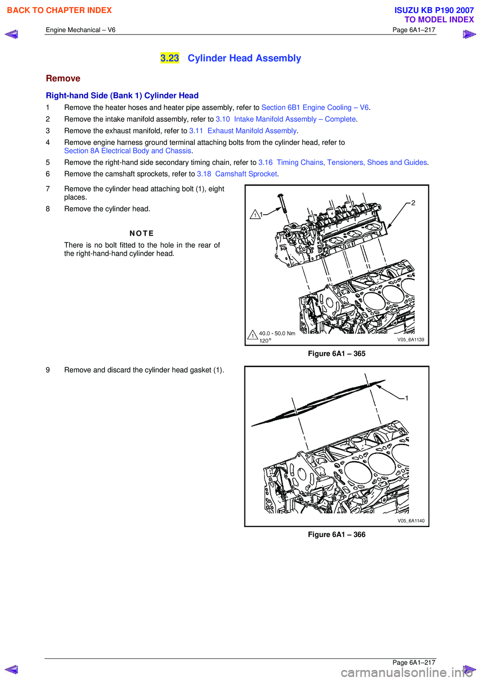
7 Remove the cylinder head attaching bolt (1), eight places.
8 Remove the cylinder head.
NOTE
There is no bolt fitted to the hole in the rear of
the right-hand-hand cylinder head.
Figure 6A1 – 365
9 Remove and discard the cylinder head gasket (1).
Figure 6A1 – 366
BACK TO CHAPTER INDEX
TO MODEL INDEX
ISUZU KB P190 2007
Page 2995 of 6020

Engine Mechanical – V6 Page 6A1–218
Page 6A1–218
Left-hand Side (Bank 2) Cylinder Head
1 Remove the intake manifold assembly, refer to 3.10 Intake Manifold Assembly – Complete .
2 Remove the exhaust manifold, refer to 3.11 Exhaust Manifold Assembly.
3 Remove the power steering reservoi r and pump mounting brackets, refer to 3.8 Power Steering Pump Bracket.
NOTE
Do not disconnect the power steering pipes
and/or hoses.
4 Remove the oil filter adapter upper bolt. NOTE
Do not remove the oil filter adapter.
5 Remove the engine coolant temper ature (ECT) sensor, refer to Section 6C1-3 Engine Management – V6 – Service
Operations .
6 Remove engine harness ground terminal attach ing bolt from cylinder head, refer to Section 8A Electrical Body &
Chassis .
7 Remove the left-hand bank secondary timing chain, refer to 3.16 Timing Chains, Tensioners, Shoes and Guides.
8 Remove the camshaft position actuators, refer to 3.18 Camshaft Sprocket.
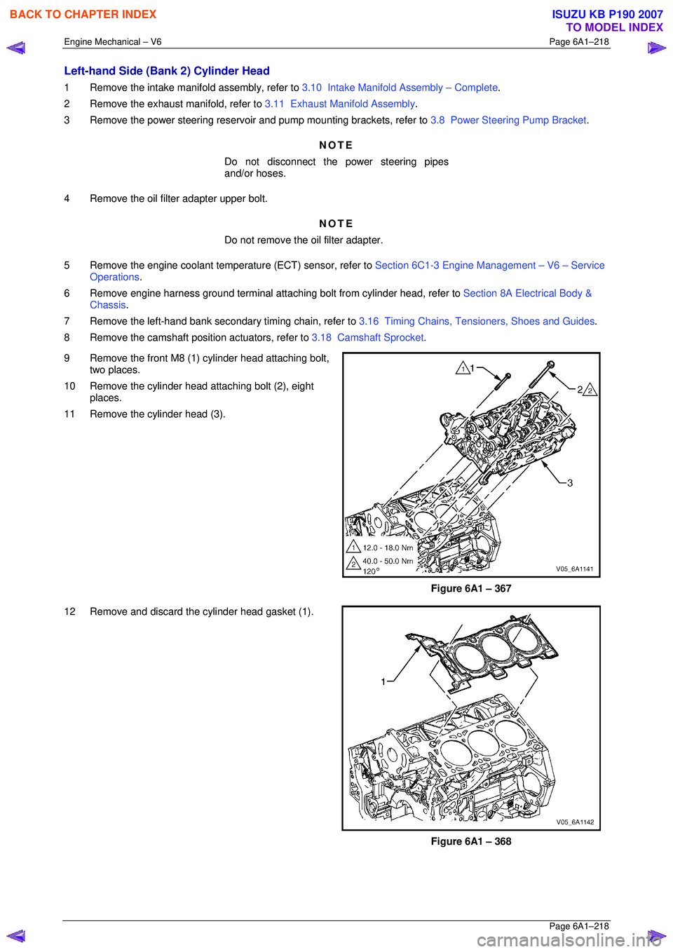
9 Remove the front M8 (1) cylinder head attaching bolt, two places.
10 Remove the cylinder head attaching bolt (2), eight places.
11 Remove the cylinder head (3).
Figure 6A1 – 367
12 Remove and discard the cylinder head gasket (1).
Figure 6A1 – 368
BACK TO CHAPTER INDEX
TO MODEL INDEX
ISUZU KB P190 2007
Page 3019 of 6020

Engine Mechanical – V6 Page 6A1–242
Page 6A1–242
Plug the fuel feed hose after removal to
prevent dirt entering the pipe.
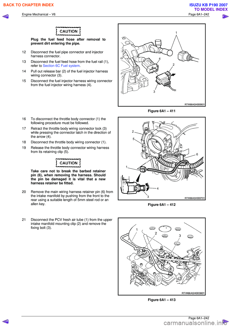
12 Disconnect the fuel pipe connector and injector harness connector.
13 Disconnect the fuel feed hose from the fuel rail (1),
refer to Section 6C Fuel system .
14 Pull out release bar (2) of the fuel injector harness
wiring connector (3).
15 Disconnect the fuel injector harness wiring connector from the fuel injector wiring harness (4).
Figure 6A1 – 411
16 To disconnect the throttle body connector (1) the following procedure must be followed.
17 Retract the throttle body wiring connector lock (3) while pressing the connector la tch in the direction of
the arrow (4).
18 Disconnect the throttle body wiring connector (1).
19 Release the throttle body connector wiring harness from its retaining clip (5).
Take care not to break the barbed retainer
pin (6), when removing the harness. Should
the pin be damaged it is vital that a new
harness retainer be fitted.
20 Remove the main wiring harness retainer pin (6) from the intake manifold by pushing from the front to the
rear using a suitable lengt h of 5mm steel rod or an
allen key.
Figure 6A1 – 412
21 Disconnect the PCV fresh air tube (1) from the upper intake manifold mounting clip (2) and remove the
fixing bolt (3).
Figure 6A1 – 413
BACK TO CHAPTER INDEX
TO MODEL INDEX
ISUZU KB P190 2007
Page 3021 of 6020
Engine Mechanical – V6 Page 6A1–244
Page 6A1–244
28 Remove the centre exhaust pipe (1), refer to
Section 6F Exhaust System - V6 .
Figure 6A1 – 417
29 Disconnect the two post-catalytic converter oxygen sensor wiring harness connectors, 1 each bank.
Figure 6A1 – 418
30 Disconnect the two pre-catalytic converter oxygen sensor wiring harness connectors, 1 each bank.
31 Remove the front exhaust flange nuts, three each bank.
32 Remove the front left-hand exhaust pipe from the rubber mount.
33 Remove the front exhaust pipes from the vehicle, for further information, refer to Section 6F Exhaust
System - V6 .
Figure 6A1 – 419
34 Remove the transfer case from t he vehicle (4WD Only), refer to Section 7D Transfer Case and Adaptor Housing .
BACK TO CHAPTER INDEX
TO MODEL INDEX
ISUZU KB P190 2007
Page 3022 of 6020
Engine Mechanical – V6 Page 6A1–245
Page 6A1–245
35 Disconnect the harness connector from the transmission, refer to Section 7B1 Manual Transmission – V6 or
Section 7C1, Section 7C2, Section 7C3 or Section 7C4 for automatic transmission.
36 Remove the left-hand side exhaust manifold upper heat shield (1), (Automatic transmission only).
Figure 6A1 – 420
37 Progressively loosen the seven exhaust manifold attaching bolts (2), working from the outside to the
centre and then remove the bolts.
38 Manoeuvre the exhaust manifold (3), away from the cylinder head.
39 Remove and discard the exhaust manifold to cylinder head gasket.
Figure 6A1 – 421
40 Remove the engine oil level indicator assembly (1), (automatic transmission only).
41 Remove the left-hand side exhaust manifold, (automatic transmission only).
Figure 6A1 – 422
BACK TO CHAPTER INDEX
TO MODEL INDEX
ISUZU KB P190 2007
Page 3024 of 6020
Engine Mechanical – V6 Page 6A1–247
Page 6A1–247
44 Remove the left-hand side engine mount (1),
(automatic transmission only).
Figure 6A1 – 426
45 Unclip the oil level s ensor harness from the heat
shield (1).
a Remove the heat shield retaining screw (2).
b Remove the lower starter motor attaching bolt (3).
c Remove the heat shield.
d Remove the upper starter motor retaining bolt (3).
46 Remove the starter motor from the engine block and lower the starter motor as far as possible to gain
access to the wiring harness connections.
47 Remove the starter moto r, (automatic transmission
only).
Figure 6A1 – 427
48 Reinstall the left-hand side engine mount (1), (automatic transmission only).
49 Remove the transmission assembly, refer to Section 7C1 Automatic – 4L60E – General
Information .
Figure 6A1 – 428
BACK TO CHAPTER INDEX
TO MODEL INDEX
ISUZU KB P190 2007
Page 3027 of 6020
Engine Mechanical – V6 Page 6A1–250
Page 6A1–250
57 Unclip and remove the generator wiring harness
connector (1), Remove ba ttery connection attaching
nut (4), and remove the battery harness cable (2)
from the connection stud.
Figure 6A1 – 435
58 Remove the generator attaching bolts (1, 2, and 4) three places, then remove the generator (3) from the
mounting bracket.
Figure 6A1 – 436
59 Remove the idler pulley attaching bolt and remove the idler pulley (1).
60 Remove the generator bracket attaching bolts, five places, and remove the generator mounting bracket
(2).
Figure 6A1 – 437
BACK TO CHAPTER INDEX
TO MODEL INDEX
ISUZU KB P190 2007
Page 3029 of 6020

Engine Mechanical – V6 Page 6A1–252
Page 6A1–252
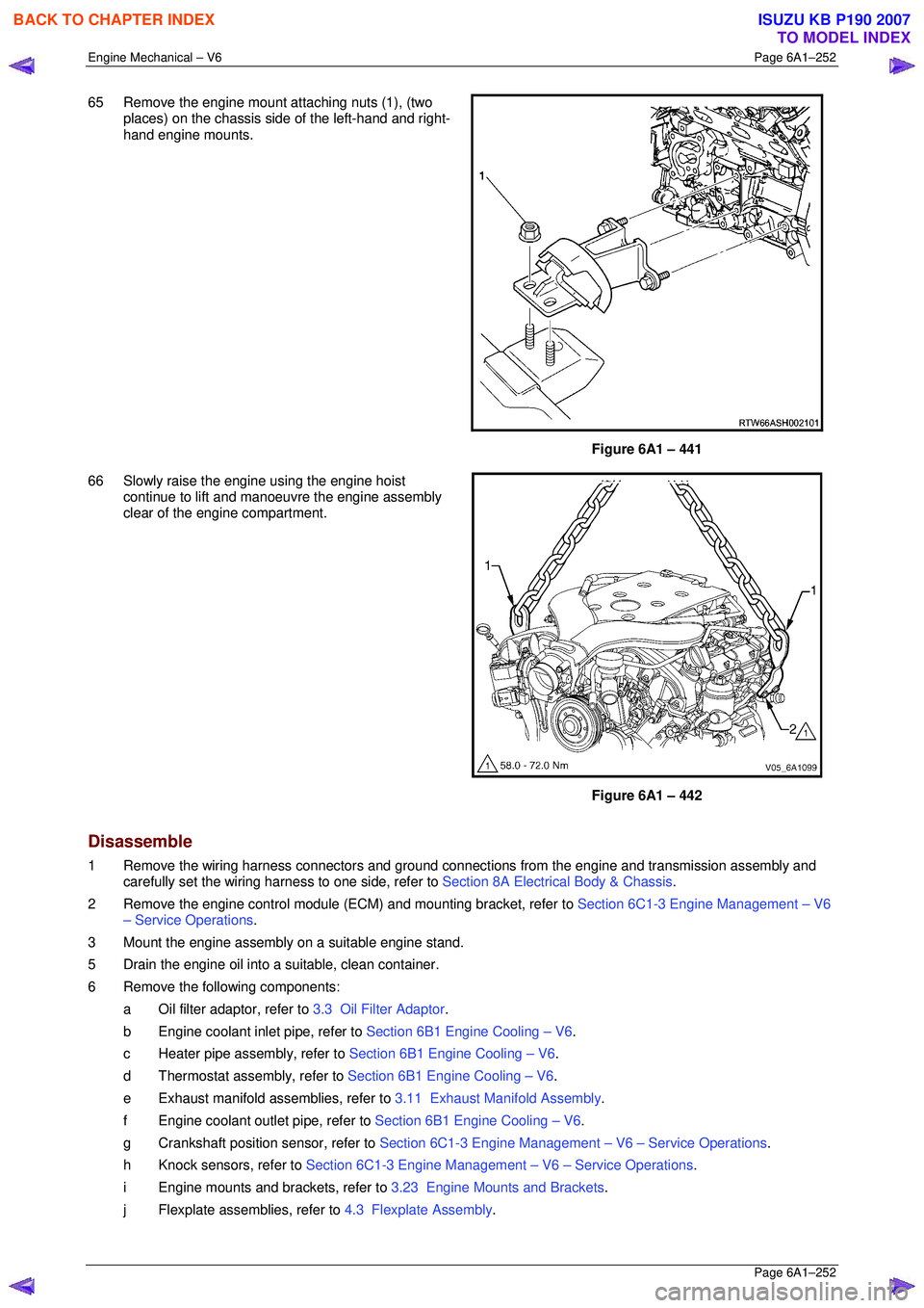
65 Remove the engine mount attaching nuts (1), (two
places) on the chassis si de of the left-hand and right-
hand engine mounts.
Figure 6A1 – 441
66 Slowly raise the engine using the engine hoist continue to lift and manoeuvre the engine assembly
clear of the engine compartment.
Figure 6A1 – 442
Disassemble
1 Remove the wiring harness connectors and ground connec tions from the engine and transmission assembly and
carefully set the wiring harness to one side, refer to Section 8A Electrical Body & Chassis.
2 Remove the engine control module (ECM) and mounting bracket, refer to Section 6C1-3 Engine Management – V6
– Service Operations .
3 Mount the engine assembly on a suitable engine stand.
5 Drain the engine oil into a suitable, clean container.
6 Remove the following components: a Oil filter adaptor, refer to 3.3 Oil Filter Adaptor.
b Engine coolant inlet pipe, refer to Section 6B1 Engine Cooling – V6.
c Heater pipe assembly, refer to Section 6B1 Engine Cooling – V6.
d Thermostat assembly, refer to Section 6B1 Engine Cooling – V6.
e Exhaust manifold a ssemblies, refer to 3.11 Exhaust Manifold Assembly .
f Engine coolant outlet pipe, refer to Section 6B1 Engine Cooling – V6.
g Crankshaft position sensor, refer to Section 6C1-3 Engine Management – V6 – Service Operations.
h Knock sensors, refer to Section 6C1-3 Engine Management – V6 – Service Operations.
i Engine mounts and brackets, refer to 3.23 Engine Mounts and Brackets.
j Flexplate assemblies, refer to 4.3 Flexplate Assembly.
BACK TO CHAPTER INDEX
TO MODEL INDEX
ISUZU KB P190 2007