Page 2554 of 6020
Engine Mechanical – V6 Page 6A1–75
CAUTION
Tighten the intake manifold bolts in a circular
pattern starting at the centre bolt and moving
outward.
4 Ensure that all fasteners are tightened to the correct torque specification. Upper intake manifold to lower intake
manifold attaching bolt torque specification .......23.0 Nm
Upper intake manifold to cylinder
head attaching bolt torque specification .............23.0 Nm
Lower intake manifold to cylinder
head attaching bolt torque specification .............23.0 Nm
Fuel injector wiring harness bracket
attaching bolt torque specification ........................9.0 Nm
Incorrect wiring connector installation may
cause component malfunction or component
damage.
5 Ensure all wiring connectors are fully engaged and if applicable, locked in place.
6 Ensure all wiring harnesses are correctly routed and attached securely in their retaining clips.
7 Ensure that all hoses and pipes are routed correctly and that any retaining clips are correctly installed.
8 After installation pull on any quick connect fittings to check that each is correctly installed.
9 Start and run the engine to check for correct operation.
3.11 Exhaust Manifold Assembly
Remove
Allow the engine to cool before commencing.
Disconnection of the battery affects certain
vehicle electronic systems, refer to 1.1
WARNING, CAUTION and NOTES before
disconnecting the battery.
1 Disconnect the battery negative terminal.
BACK TO CHAPTER INDEX
TO MODEL INDEX
ISUZU KB P190 2007
Page 2555 of 6020
Engine Mechanical – V6 Page 6A1–76
2 Remove the oxygen sensor harness connector (1)
from the retaining bracket.
3 Disconnect the oxygen sensor wiring harness connector from the engine wiring harness connector
(2).
4 Unclip the oxygen sensor wiring harness retaining clip and move aside.
5 For the left-hand side: Remove the oil level indicator tube.
6 Raise the front of the vehicle and place on stands, refer to 0A General Information.
7 W orking from under the vehicle, remove the two exhaust manifold to exhaust pipe flange nuts, refer to
6F Exhaust System - V6 - V6.
Figure 6A1 – 56
8 Remove the three bolts attaching the exhaust manifold outer heat shield (1) to the exhaust manifold
(2).
Figure 6A1 – 57
9 Progressively loosen the seven exhaust manifold attaching bolts (2), working from the outside to the
centre and then remove the bolts.
10 Manoeuvre the exhaust manifold (3), away from the cylinder head.
11 Remove and discard the exhaust manifold to cylinder head gasket.
Figure 6A1 – 58
BACK TO CHAPTER INDEX
TO MODEL INDEX
ISUZU KB P190 2007
Page 2557 of 6020
Engine Mechanical – V6 Page 6A1–78
2 Position a new exhaust manifold gasket onto the exhaust manifold.
3 Apply a 5 mm bead of Loctite 272 thread sealant (or equivalent) to the threads of the exhaust manifold attaching bolts.
4 Install the bolts into the exhaust manifold. This will prevent the gasket from falling off the manifold.
5 Manoeuvre the exhaust manifold into position and install the exhaust manifold attaching bolts.
6 From underneath the vehicle install the exhaust manifold to exhaust pipe flange nuts.
7 Tighten the exhaust manifold attaching bolts to the correct torque specification.
NOTE
When tightening the exhaust manifold to cylinder
head attaching bolts, begin with the centre bolts,
then alternate from side to side to the outer bolts.
Exhaust manifold to cylinder head
attaching bolt torque specification ...........17.0 – 23.0 Nm
8 Apply an anti seize compound such as Caltex Kopr-Kote (or equivalent) to the cleaned heat shield bolt threads. Install the heat shield attaching bolts and tighten to the correct torque specification.
Exhaust manifold heat shield attaching
bolt torque specification ............................8.0 – 12.0 Nm
9 For the right-hand side, install the battery harness ground cable attaching nut through the ground terminal and lower coolant tube mounting lug, and tighten to the correct torque specification.
Battery harness ground terminal
attaching nut torque specification.......................13.0 Nm
BACK TO CHAPTER INDEX
TO MODEL INDEX
ISUZU KB P190 2007
Page 2558 of 6020
Engine Mechanical – V6 Page 6A1–79
3.12 Camshaft Cover
Remove
1 Remove the intake manifold assembly, refer to 3.10 Intake Manifold Assembly – Complete.
2 For the left-hand side, remove the evaporative (EVAP) emission canister purge solenoid, refer to 6C1-3 Engine Management – V6 – Service Operations.
3 Remove the two bolts (1) attaching the engine wiring harness former to the rear of the cylinder heads.
4 Unclip the transmission vent tube (2) from the engine wiring harness.
Figure 6A1 – 61
5 Disconnect the oxygen sensor wiring harness connector (1) from the engine wiring harness (2), left-
hand shown, right-hand similar.
Figure 6A1 – 62
BACK TO CHAPTER INDEX
TO MODEL INDEX
ISUZU KB P190 2007
Page 2559 of 6020
Engine Mechanical – V6 Page 6A1–80
6 Remove the bolt (1) attaching the ground connector
(2) to the cylinder head.
7 Fro the left-hand side, disconnect the engine coolant temperature (ECT) sensor wiring connector (3).
8 Unclip the engine wiring harness retaining lugs from the side of the camshaft cover.
Figure 6A1 – 63
9 For the right-hand side, remove the engine wiring harness retaining clip (1) from the engine control
module (ECM) bracket (2).
Figure 6A1 – 64
10 Disconnect the camshaft position (CMP) sensor wiring connector (1).
11 Unclip the engine wiring harness retaining lug (3) from the front of the camshaft cover.
12 Remove the ignition coil assemblies; refer to 6C1-3 Engine Management – V6 – Service Operations.
13 Move the engine wiring harness clear of the camshaft cover.
Figure 6A1 – 65
BACK TO CHAPTER INDEX
TO MODEL INDEX
ISUZU KB P190 2007
Page 2563 of 6020
Engine Mechanical – V6 Page 6A1–84
8 Remove Tool No. EN-46101 (1).
9 Tighten all remaining fasteners to the correct torque specification.
Engine ground connector bolt
torque specification ............................................10.0 Nm
Engine wiring harness former attaching
bolt torque specification ..........................12.0 – 16.0 Nm
Figure 6A1 – 74
3.13 Crankshaft Balancer Assembly
Remove
1 Remove the accessory drive belt, refer to 3.5 Accessory Drive Belt.
2 Remove the starter motor, refer to 6D1-2_ Starting System.
3 Install Tool No. EN-46106 (1) into the starter motor opening to stop the camshaft from rotating.
Figure 6A1 – 75
BACK TO CHAPTER INDEX
TO MODEL INDEX
ISUZU KB P190 2007
Page 2640 of 6020
Engine Mechanical – V6 Page 6A1–161
Reinstall
1 Fill the stationary hydraulic lash adjuster (SHLA) with
clean engine oil. Take precautions to prevent
scratching the pivot sphere area of the SHLA.
2 Lubricate the SHLA bores in the cylinder head with clean engine oil.
3 Install the SHLA in the cylinder head (2).
4 Apply a liberal amount of commercially available camshaft/lifter prelube to the SHLA pivot spheres.
5 Install the rocker arms, refer to 3.20 Rocker Arm.
CAUTION
Ensure each lash adjuster (1) is filled with
clean engine oil and the adjuster does not
tip over, plunger down, before the
installation. The loss of oil in the adjuster
lower pressure chamber, or the dry
stroking/cycling of the adjuster plunger, will
allow air to enter the high pressure chamber
of the valve lifter. Air in the high pressure
chamber of the adjuster may not be purged
causing cavitation and extensive engine
component damage.
Figure 6A1 – 274
3.22 Cylinder Head Assembly
Remove
Right-hand Side (Bank 1) Cylinder Head
1 Remove the heater hoses and heater pipe assembly, refer to 6B1 Engine Cooling – V6.
2 Remove the intake manifold assembly, refer to 3.10 Intake Manifold Assembly – Complete.
3 Remove the exhaust manifold, refer to 3.11 Exhaust Manifold Assembly.
4 Remove engine harness ground terminal attaching bolts from the cylinder head, refer to 8A Electrical Body and Chassis.
5 Remove the right-hand side secondary timing chain, refer to 3.16 Timing Chains, Tensioners, Shoes and Guides.
6 Remove the camshaft sprockets, refer to 3.18 Camshaft Sprocket.
7 Remove the cylinder head attaching bolt (1), eight places.
8 Remove the cylinder head.
NOTE
There is no bolt fitted to the hole in the rear of
the right-hand-hand cylinder head.
Figure 6A1 – 275
BACK TO CHAPTER INDEX
TO MODEL INDEX
ISUZU KB P190 2007
Page 2641 of 6020
Engine Mechanical – V6 Page 6A1–162
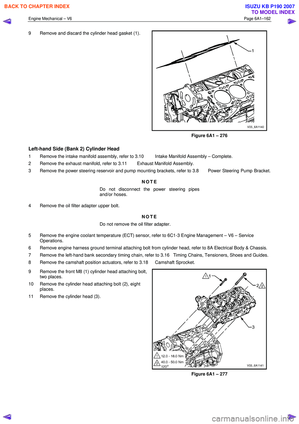
9 Remove and discard the cylinder head gasket (1).
Figure 6A1 – 276
Left-hand Side (Bank 2) Cylinder Head
1 Remove the intake manifold assembly, refer to 3.10 Intake Manifold Assembly – Complete.
2 Remove the exhaust manifold, refer to 3.11 Exhaust Manifold Assembly.
3 Remove the power steering reservoir and pump mounting brackets, refer to 3.8 Power Steering Pump Bracket.
NOTE
Do not disconnect the power steering pipes
and/or hoses.
4 Remove the oil filter adapter upper bolt. NOTE
Do not remove the oil filter adapter.
5 Remove the engine coolant temperature (ECT) sensor, refer to 6C1-3 Engine Management – V6 – Service Operations.
6 Remove engine harness ground terminal attaching bolt from cylinder head, refer to 8A Electrical Body & Chassis.
7 Remove the left-hand bank secondary timing chain, refer to 3.16 Timing Chains, Tensioners, Shoes and Guides.
8 Remove the camshaft position actuators, refer to 3.18 Camshaft Sprocket.
9 Remove the front M8 (1) cylinder head attaching bolt, two places.
10 Remove the cylinder head attaching bolt (2), eight places.
11 Remove the cylinder head (3).
Figure 6A1 – 277
BACK TO CHAPTER INDEX
TO MODEL INDEX
ISUZU KB P190 2007