Page 3007 of 6020
Engine Mechanical – V6 Page 6A1–230
Page 6A1–230
Assemble
1 Install the cylinder head coolant threaded plugs (1)
and tighten to the correct torque specification.
Cylinder head thre aded plug .............................. 31.0 Nm
Figure 6A1 – 388
2 Install the cylinder head oil gallery expansion plugs (1).
Figure 6A1 – 389
CAUTION
• Never reuse a valve stem oil seal. Always
use new seals when assembling the
cylinder head.
• Force should only be applied to the valve
spring contact area of the new valve stem
oil seal during installation.
3 Fit the valve stem oil seal s onto the guides using Tool
No. EN-46116 (1).
4 Push and twist the valve stem oil seal into position on the valve guide until the s eal positively locks on the
guide using Tool No. EN-46116.
5 Lubricate the valve stem and valve guide ID with clean engine oil.
Figure 6A1 – 390
BACK TO CHAPTER INDEX
TO MODEL INDEX
ISUZU KB P190 2007
Page 3008 of 6020

Engine Mechanical – V6 Page 6A1–231
Page 6A1–231
CAUTION
The valve stem oil seal must not come loose
from the valve guide when the valve (1) is
installed.
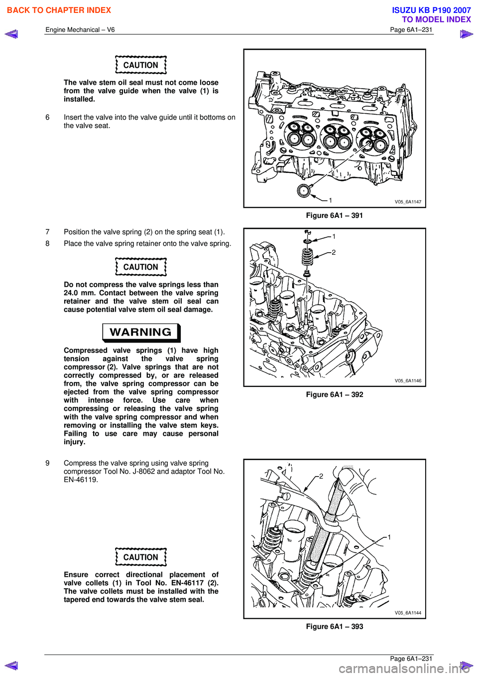
6 Insert the valve into the valve guide until it bottoms on
the valve seat.
Figure 6A1 – 391
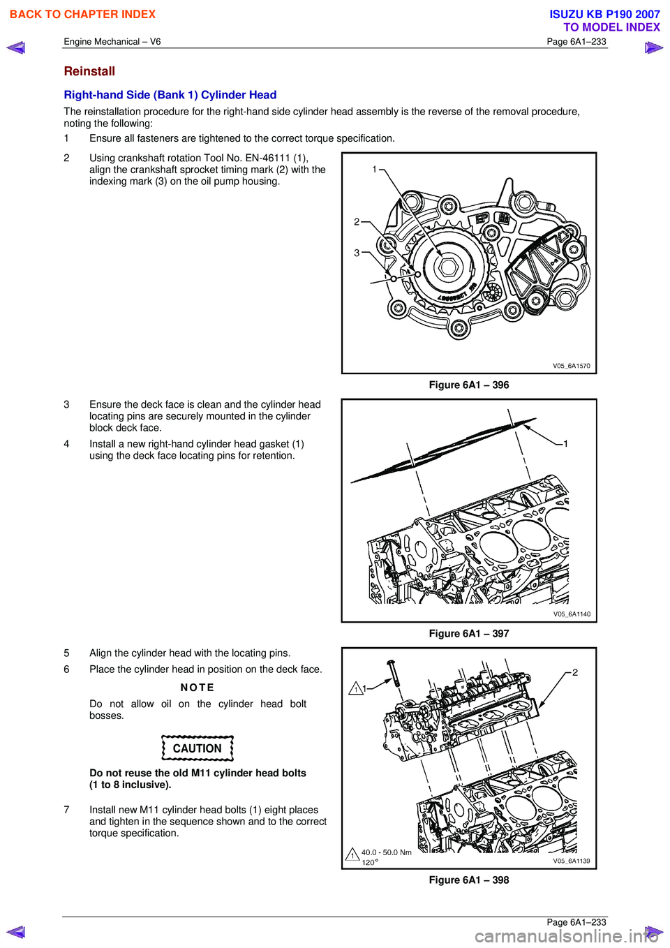
7 Position the valve spring (2) on the spring seat (1).
8 Place the valve spring retainer onto the valve spring.
CAUTION
Do not compress the valve springs less than
24.0 mm. Contact between the valve spring
retainer and the valve stem oil seal can
cause potential valve stem oil seal damage.
Compressed valve springs (1) have high
tension against the valve spring
compressor (2). Valve springs that are not
correctly compressed by, or are released
from, the valve spring compressor can be
ejected from the valve spring compressor
with intense force. Use care when
compressing or releasing the valve spring
with the valve spring compressor and when
removing or installing the valve stem keys.
Failing to use care may cause personal
injury.
Figure 6A1 – 392
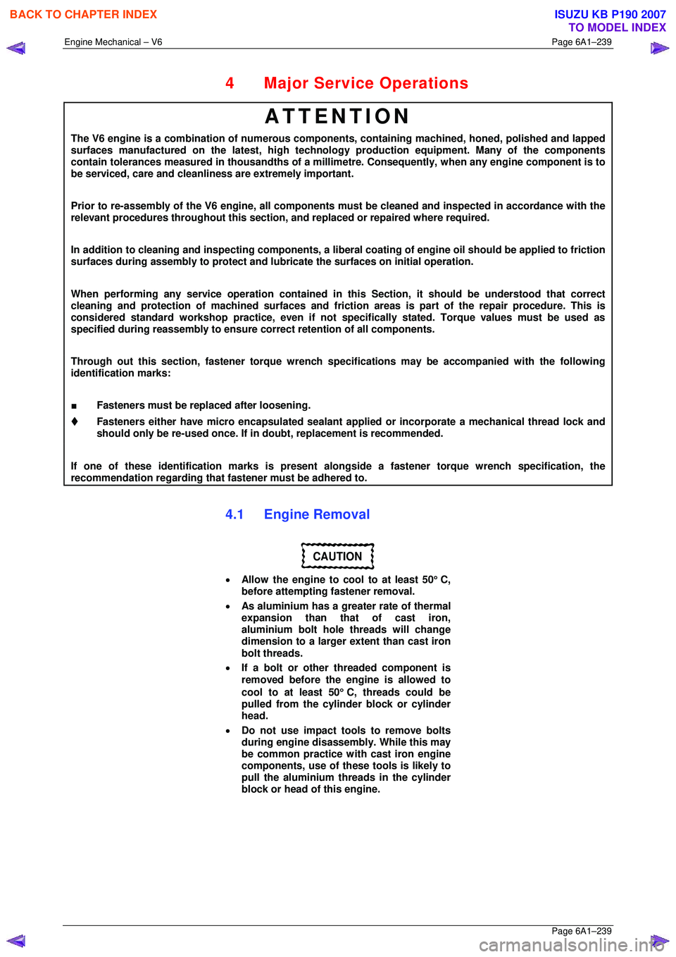
9 Compress the valve spring using valve spring compressor Tool No. J-8062 and adaptor Tool No.
EN-46119.
CAUTION
Ensure correct directional placement of
valve collets (1) in Tool No. EN-46117 (2).
The valve collets must be installed with the
tapered end towards the valve stem seal.
Figure 6A1 – 393
BACK TO CHAPTER INDEX
TO MODEL INDEX
ISUZU KB P190 2007
Page 3010 of 6020

Engine Mechanical – V6 Page 6A1–233
Page 6A1–233
Reinstall
Right-hand Side (Bank 1) Cylinder Head
The reinstallation procedure for the right-hand side cylinder head assembly is the reverse of the removal procedure,
noting the following:
1 Ensure all fasteners are tightened to the correct torque specification.
2 Using crankshaft rotation Tool No. EN-46111 (1), align the crankshaft sprocket timing mark (2) with the
indexing mark (3) on the oil pump housing.
Figure 6A1 – 396
3 Ensure the deck face is clean and the cylinder head locating pins are securely mounted in the cylinder
block deck face.
4 Install a new right-hand cylinder head gasket (1) using the deck face locating pins for retention.
Figure 6A1 – 397
5 Align the cylinder head with the locating pins.
6 Place the cylinder head in position on the deck face.
NOTE
Do not allow oil on the cylinder head bolt
bosses.
CAUTION
Do not reuse the old M11 cylinder head bolts
(1 to 8 inclusive).
7 Install new M11 cylinder head bolts (1) eight places and tighten in the sequence shown and to the correct
torque specification.
Figure 6A1 – 398
BACK TO CHAPTER INDEX
TO MODEL INDEX
ISUZU KB P190 2007
Page 3011 of 6020
Engine Mechanical – V6 Page 6A1–234
Page 6A1–234
�„ Cylinder head M11 attaching bolt
torque specification:
Stage 1:............. 40.0 – 50.0 Nm
Stage 2:.............................. 120°
Figure 6A1 – 399
Left-hand Side (Bank 2) Cylinder Head
The reinstallation procedure for the left-hand side cylinder head a ssembly is the reverse of the removal procedure, noting
the following:
1 Ensure all fasteners are tightened to the correct torque specification.
2 Using crankshaft rotation Tool No. EN-46111 (1), align the crankshaft sprocket timing mark (2) with the
indexing mark (3) on the oil pump housing.
Figure 6A1 – 400
3 Ensure the deck face is clean and the cylinder head locating pins are securely mounted in the cylinder
block deck face.
4 Install a new cylinder head gasket (1) using the deck face locating pins for retention.
Figure 6A1 – 401
BACK TO CHAPTER INDEX
TO MODEL INDEX
ISUZU KB P190 2007
Page 3012 of 6020
Engine Mechanical – V6 Page 6A1–235
Page 6A1–235
5 Align the cylinder head with the locating pins.
6 Place the cylinder head in position on the deck face.
NOTE
Do not allow oil on the cylinder head bolt
bosses.
CAUTION
Do not reuse the old M11 cylinder head bolts
(1 to 8 inclusive).
7 Install new M11 cylinder head bolt (1), eight places, and tighten in the sequence shown and to the correct
torque specification.
Figure 6A1 – 402
8 Install the front M8 cylinder head bolt (2), two places, and tighten in the sequence (9 and 10) and to the
correct torque.
�„ Cylinder head M11 attaching bolt
torque specification:
Stage 1:............. 40.0 – 50.0 Nm
Stage 2:.............................. 120°
�„ M8 cylinder head bolt
torque specification
Stage 1:............. 12.0 – 18.0 Nm
Stage 2:................................ 60°
Figure 6A1 – 403
BACK TO CHAPTER INDEX
TO MODEL INDEX
ISUZU KB P190 2007
Page 3016 of 6020

Engine Mechanical – V6 Page 6A1–239
Page 6A1–239
4 Major Service Operations
ATTENTION
The V6 engine is a combination of numerous components, containing machined, honed, polished and lapped
surfaces manufactured on the latest, high technology production equipment. Many of the components
contain tolerances measured in thousa ndths of a millimetre. Consequently, when any e ngine component is to
be serviced, care and cleanliness are extremely important.
Prior to re-assembly of the V6 engi ne, all components must be cleaned and inspected in accordance with the
relevant procedures throughout this section, and replaced or repaired where required.
In addition to cleaning and inspecting components, a liberal coating of engine oil should be applied to friction
surfaces during assembly to protect and lubr icate the surfaces on initial operation.
When performing any service operation contained in this Section, it should be understood that correct
cleaning and protection of machined surfaces and fricti on areas is part of the repair procedure. This is
considered standard workshop practice, even if not specifically stated. Torque values must be used as
specified during reassembly to ensure correct retention of all components.
Through out this section, fastener torque wrench sp ecifications may be accompanied with the following
identification marks:
■ Fasteners must be replaced after loosening.
Fasteners either have micro encapsulated sealant a pplied or incorporate a mechanical thread lock and
should only be re-used once. If in doubt, replacement is recommended.
If one of these identification marks is present alongs ide a fastener torque wrench specification, the
recommendation regarding that fastener must be adhered to.
4.1 Engine Removal
CAUTION
• Allow the engine to cool to at least 50 ° C,
before attempting fastener removal.
• As aluminium has a greater rate of thermal
expansion than that of cast iron,
aluminium bolt hole threads will change
dimension to a larger extent than cast iron
bolt threads.
• If a bolt or other threaded component is
removed before the engine is allowed to
cool to at least 50 ° C, threads could be
pulled from the cylinder block or cylinder
head.
• Do not use impact tools to remove bolts
during engine disassembly. While this may
be common practice with cast iron engine
components, use of th ese tools is likely to
pull the aluminium threads in the cylinder
block or head of this engine.
BACK TO CHAPTER INDEX
TO MODEL INDEX
ISUZU KB P190 2007
Page 3022 of 6020
Engine Mechanical – V6 Page 6A1–245
Page 6A1–245
35 Disconnect the harness connector from the transmission, refer to Section 7B1 Manual Transmission – V6 or
Section 7C1, Section 7C2, Section 7C3 or Section 7C4 for automatic transmission.
36 Remove the left-hand side exhaust manifold upper heat shield (1), (Automatic transmission only).
Figure 6A1 – 420
37 Progressively loosen the seven exhaust manifold attaching bolts (2), working from the outside to the
centre and then remove the bolts.
38 Manoeuvre the exhaust manifold (3), away from the cylinder head.
39 Remove and discard the exhaust manifold to cylinder head gasket.
Figure 6A1 – 421
40 Remove the engine oil level indicator assembly (1), (automatic transmission only).
41 Remove the left-hand side exhaust manifold, (automatic transmission only).
Figure 6A1 – 422
BACK TO CHAPTER INDEX
TO MODEL INDEX
ISUZU KB P190 2007
Page 3024 of 6020
Engine Mechanical – V6 Page 6A1–247
Page 6A1–247
44 Remove the left-hand side engine mount (1),
(automatic transmission only).
Figure 6A1 – 426
45 Unclip the oil level s ensor harness from the heat
shield (1).
a Remove the heat shield retaining screw (2).
b Remove the lower starter motor attaching bolt (3).
c Remove the heat shield.
d Remove the upper starter motor retaining bolt (3).
46 Remove the starter motor from the engine block and lower the starter motor as far as possible to gain
access to the wiring harness connections.
47 Remove the starter moto r, (automatic transmission
only).
Figure 6A1 – 427
48 Reinstall the left-hand side engine mount (1), (automatic transmission only).
49 Remove the transmission assembly, refer to Section 7C1 Automatic – 4L60E – General
Information .
Figure 6A1 – 428
BACK TO CHAPTER INDEX
TO MODEL INDEX
ISUZU KB P190 2007