Page 2847 of 6020

Engine Mechanical – V6 Page 6A1–70
Page 6A1–70
3.3 Oil Filter Adaptor
Remove
Disconnection of the battery affects
certain vehicle electronic systems, refer to
1.1 WARNING, CAUTION and NOTES before
disconnecting the battery.
1 Disconnect the battery negative terminal.
2 Disconnect the wiring harness connecto r from the oil pressure sender.
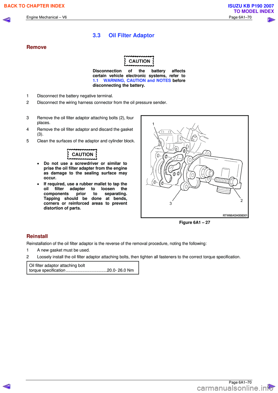
3 Remove the oil filter adaptor attaching bolts (2), four
places.
4 Remove the oil filter adaptor and discard the gasket (3).
5 Clean the surfaces of t he adaptor and cylinder block.
• Do not use a screwdriver or similar to
prise the oil filter adapter from the engine
as damage to the sealing surface may
occur.
• If required, use a rubber mallet to tap the
oil filter adapter to loosen the
components prior to separating.
Tapping should be done at bends,
corners or reinforced areas to prevent
distortion of parts.
Figure 6A1 – 27
Reinstall
Reinstallation of the oil filter adaptor is the reverse of the remo val procedure, noting the following:
1 A new gasket must be used.
2 Loosely install the oil filter adaptor attaching bolts, then tighten all fast eners to the correct torque specification.
Oil filter adaptor attaching bolt
torque specificatio n ...................................20.0- 26.0 Nm
BACK TO CHAPTER INDEX
TO MODEL INDEX
ISUZU KB P190 2007
Page 2848 of 6020
Engine Mechanical – V6 Page 6A1–71
Page 6A1–71
3.4 Oil Level Indicator Tube
Remove
1 Remove the oil level indicator from the oil level indicator tube.
2 Remove the bolt (2) attaching the oil level indicator tube (1) and engine wiring harness retaining bracket.
3 Withdraw the oil level indi cator tube from the oil pan.
4 Remove and discard the o-ring at the bottom of the oil level indicator tube.
Figure 6A1 – 28
Reinstall
Reinstallation of the oil level indicator tube is the reverse of the removal procedure, noting the following:
1 Install a new oil level indicator o-ring.
2 Ensure the attaching bolt passes through the engine wiring harness retaining bracket.
3 Tighten bolt to the correct torque specification.
Oil level indicator tube attaching bolt
torque specificatio n ................................... 8. 0 – 12.0 Nm
BACK TO CHAPTER INDEX
TO MODEL INDEX
ISUZU KB P190 2007
Page 2868 of 6020

Engine Mechanical – V6 Page 6A1–91
Page 6A1–91
3.11 Exhaust Manifold Assembly
Remove
Allow the engine to cool before commencing.
Disconnection of the battery affects
certain vehicle electronic systems, refer to
1.1 WARNING, CAUTION and NOTES before
disconnecting the battery.
1 Disconnect the battery negative terminal.
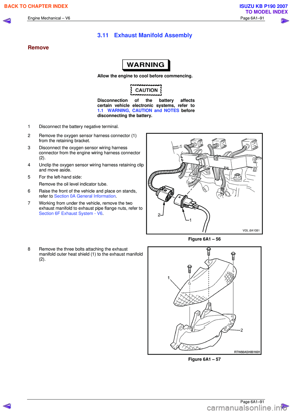
2 Remove the oxygen sensor harness connector (1) from the retaining bracket.
3 Disconnect the oxygen sensor wiring harness connector from the engine wiring harness connector
(2).
4 Unclip the oxygen sensor wiring harness retaining clip and move aside.
5 For the left-hand side: Remove the oil level indicator tube.
6 Raise the front of the vehicle and place on stands,
refer to Section 0A General Information .
7 Working from under the vehicle, remove the two exhaust manifold to exhaust pipe flange nuts, refer to
Section 6F Exhaust System - V6 .
Figure 6A1 – 56
8 Remove the three bolts attaching the exhaust manifold outer heat shield (1) to the exhaust manifold
(2).
Figure 6A1 – 57
BACK TO CHAPTER INDEX
TO MODEL INDEX
ISUZU KB P190 2007
Page 2872 of 6020
Engine Mechanical – V6 Page 6A1–95
Page 6A1–95
6 Remove the bolt (1) attaching the ground connector
(2) to the cylinder head.
7 Fro the left-hand side, disconnect the engine coolant temperature (ECT) sensor wiring connector (3).
8 Unclip the engine wiring harness retaining lugs from the side of the camshaft cover.
Figure 6A1 – 63
9 For the right-hand side, remove the engine wiring harness retaining clip (1) from the engine control
module (ECM) bracket (2).
Figure 6A1 – 64
10 Disconnect the camshaft position (CMP) sensor wiring connector (1).
11 Unclip the engine wiring harness retaining lug (3) from the front of the camshaft cover.
12 Remove the ignition coil assemblies; refer to Section 6C1-3 Engine Management – V6 – Service
Operations .
13 Move the engine wiring harness clear of the camshaft cover.
Figure 6A1 – 65
BACK TO CHAPTER INDEX
TO MODEL INDEX
ISUZU KB P190 2007
Page 2878 of 6020

Engine Mechanical – V6 Page 6A1–101
Page 6A1–101
Clean and Inspect
1 Using a suitable non-corrosive cleaning solvent and a soft bristled parts cleaning brush, clean the crankshaft
balancer assembly.
Safety glasses must be worn when using
compressed air.
2 Dry the crankshaft balancer assembly using compressed air.
3 Inspect the crankshaft balancer assemb ly for the following fault conditions:
• Hub to crankshaft inner surface for wear or damage,
• Sealing surface for wear, grooving or scoring,
• Rubber ring between the hub and the pulley for wear, chunking and general deterioration, and
• Drive belt ribs of the pulley for damage.
Reinstall
CAUTION
Do not lubricate the crankshaft front oil seal
or crankshaft balancer sealing surfaces. The
crankshaft balancer must be installed onto a
dry seal.
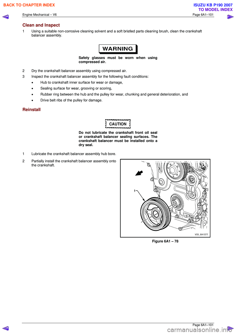
1 Lubricate the crankshaft balancer assembly hub bore.
2 Partially install the crankshaft balancer assembly onto the crankshaft.
Figure 6A1 – 78
BACK TO CHAPTER INDEX
TO MODEL INDEX
ISUZU KB P190 2007
Page 2880 of 6020
Engine Mechanical – V6 Page 6A1–103
Page 6A1–103
3.14 Crankshaft Front Seal
Replace
1 Remove the crankshaft balancer assembly, refer to 3.13 Crankshaft Balancer Assembly .
2 Using a flat bladed tool (2) or seal remover, Tool No. E-308, carefully remove the crankshaft front seal (1)
from the front cover.
Figure 6A1 – 81
3 Using crankshaft front seal installer, Tool No. J-29184 (2) and a suitable hammer, install a new crankshaft
front seal (1) until fully s eated against the front cover
housing.
4 Install the crankshaft balanc er assembly, refer to
3.13 Crankshaft Balancer Assembly .
CAUTION
Do not lubricate the crankshaft front oil seal
or crankshaft balancer sealing surfaces. The
crankshaft balancer is installed into a dry
seal.
Figure 6A1 – 82
BACK TO CHAPTER INDEX
TO MODEL INDEX
ISUZU KB P190 2007
Page 2882 of 6020
Engine Mechanical – V6 Page 6A1–105
Page 6A1–105
11 Remove the front cover assembly (1).
Figure 6A1 – 85
Disassemble
1 Remove the crankshaft front oil seal (1) from the engine front cover (2) using a flat bladed tool or seal
remover, Tool No. E-308. Discard the seal.
Figure 6A1 – 86
2 Remove the camshaft position actuator valve oil seals (1) from the engine front cover (2). Discard the
seals.
Figure 6A1 – 87
BACK TO CHAPTER INDEX
TO MODEL INDEX
ISUZU KB P190 2007
Page 2883 of 6020
Engine Mechanical – V6 Page 6A1–106
Page 6A1–106
3 Remove the coolant pump seal (1) from the engine
front cover (2). Discard the seal.
Figure 6A1 – 88
Clean
4 Remove any RTV sealant (1) from the engine front cover using a plastic or wood scraper.
CAUTION
• Insert a piece of cardboard between the
front of the oil pan and oil pump to
prevent any contaminants from falling
into the oil pan.
• Do not use a sharp or metal gasket
scraper to clean the sealing surfaces.
5 Clean out any debris from the bolt holes.
6 Clean the front cover with a suitable cleaning solvent.
7 Dry the front cover with compressed air.
Safety glasses must be worn when using
compressed air.
Figure 6A1 – 89
8 Use compressed air to remove any engine coolant from the engine cooling passages and from the top of the oil
pan oil deflector.
BACK TO CHAPTER INDEX
TO MODEL INDEX
ISUZU KB P190 2007