Page 2794 of 6020
Engine Mechanical – V6 Page 6A1–17
Page 6A1–17
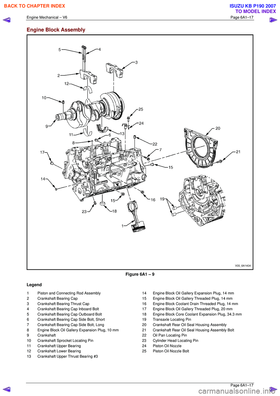
Engine Block Assembly
Figure 6A1 – 9
Legend
1 Piston and Connecting Rod Assembly
2 Crankshaft Bearing Cap
3 Crankshaft Bearing Thrust Cap
4 Crankshaft Bearing Cap Inboard Bolt
5 Crankshaft Bearing Cap Outboard Bolt
6 Crankshaft Bearing Cap Side Bolt, Short
7 Crankshaft Bearing Cap Side Bolt, Long
8 Engine Block Oil Gallery Expansion Plug, 10 mm
9 Crankshaft
10 Crankshaft Sprocket Locating Pin
11 Crankshaft Upper Bearing
12 Crankshaft Lower Bearing
13 Crankshaft Upper Thrust Bearing #3 14 Engine Block Oil Gallery Expansion Plug, 14 mm
15 Engine Block Oil Gallery Threaded Plug, 14 mm
16 Engine Block Coolant Drain Threaded Plug, 14 mm
17 Engine Block Oil Gallery Threaded Plug, 20 mm
18 Engine Block Core Coolant Expansion Plug, 34.3 mm
19 Transaxle Locating Pin
20 Crankshaft Rear Oil Seal Housing Assembly
21 Crankshaft Rear Oil Seal Housing Assembly Bolt
22 Oil Pan Locating Pin
23 Cylinder Head Locating Pin
24 Piston Oil Nozzle
25 Piston Oil Nozzle Bolt
BACK TO CHAPTER INDEX
TO MODEL INDEX
ISUZU KB P190 2007
Page 2795 of 6020
Engine Mechanical – V6 Page 6A1–18
Page 6A1–18
Pistons, Rings, Bearing and Connecting Rod
Figure 6A1 – 10
Legend
1 Connecting Rod
2 Connecting Rod Bolt
3 Connecting Rod Bush
4 Upper Connecting Rod Bearing
5 Lower Connecting Rod Bearing
6 Piston 7 Piston Pin
8 Piston Pin Retainer
9 Piston Upper Compression Ring
10 Piston Lower Compression Ring
11 Piston Oil Control Rail Ring
12 Piston Oil Control Ring Spacer
BACK TO CHAPTER INDEX
TO MODEL INDEX
ISUZU KB P190 2007
Page 2796 of 6020
Engine Mechanical – V6 Page 6A1–19
Page 6A1–19
Oil Pan Assembly
Figure 6A1 – 11
Legend
1 Oil Pan
2 Crankshaft Oil Deflector
3 Oil Pump Suction Pipe
4 Oil Pump Suction Pipe Gasket
5 Oil Pump Suction Pipe Bolt 6 Crankshaft Oil Deflector Bolt
7 Oil Pan Drain Plug
8 Oil Pan Drain Plug Sleeve
9 Engine Oil Level Sensor
BACK TO CHAPTER INDEX
TO MODEL INDEX
ISUZU KB P190 2007
Page 2797 of 6020
Engine Mechanical – V6 Page 6A1–20
Page 6A1–20
Oil Filter Assembly
Legend
1 Oil Filter Gasket
2 Oil Filter Adapter
3 Oil Filter Adapter Bolt
4 Oil Filter Element
Figure 6A1 – 12
BACK TO CHAPTER INDEX
TO MODEL INDEX
ISUZU KB P190 2007
Page 2799 of 6020
Engine Mechanical – V6 Page 6A1–22
Page 6A1–22
1.4 Engine Construction
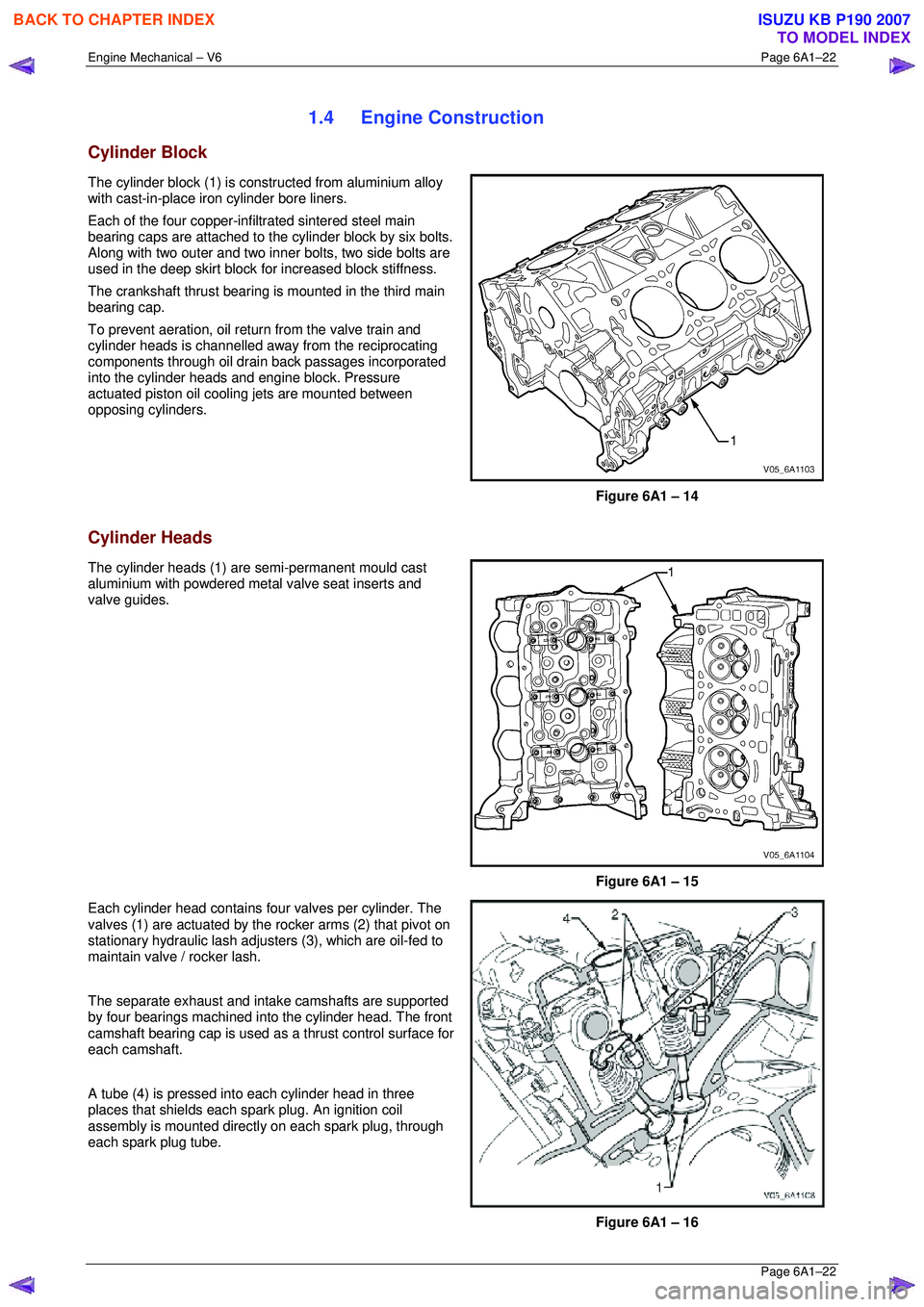
Cylinder Block
The cylinder block (1) is constructed from aluminium alloy
with cast-in-place iron cylinder bore liners.
Each of the four copper-inf iltrated sintered steel main
bearing caps are attached to the cylinder block by six bolts.
Along with two outer and two inner bolts, two side bolts are
used in the deep skirt block fo r increased block stiffness.
The crankshaft thrust bearing is mounted in the third main
bearing cap.
To prevent aeration, oil retu rn from the valve train and
cylinder heads is channelled away from the reciprocating
components through oil drain back passages incorporated
into the cylinder heads and engine block. Pressure
actuated piston oil cooling jets are mounted between
opposing cylinders.
Figure 6A1 – 14
Cylinder Heads
The cylinder heads (1) are semi-permanent mould cast
aluminium with powdered metal valve seat inserts and
valve guides.
Figure 6A1 – 15
Each cylinder head contains four valves per cylinder. The
valves (1) are actuated by the rocker arms (2) that pivot on
stationary hydraulic lash adjuste rs (3), which are oil-fed to
maintain valve / rocker lash.
The separate exhaust and intake camshafts are supported
by four bearings machined into the cylinder head. The front
camshaft bearing cap is used as a thrust control surface for
each camshaft.
A tube (4) is pressed into each cylinder head in three
places that shields each spark plug. An ignition coil
assembly is mounted directly on each spark plug, through
each spark plug tube.
Figure 6A1 – 16
BACK TO CHAPTER INDEX
TO MODEL INDEX
ISUZU KB P190 2007
Page 2800 of 6020
Engine Mechanical – V6 Page 6A1–23
Page 6A1–23
Crankshaft
The crankshaft is a forged steel design with four main bearings. The number three main bearing controls crankshaft
thrust. A crankshaft position reluctor wheel is pressed onto the rear of the crankshaft, in front of the rear main journal.
The crankshaft is internally balanced with an integral oil pum p drive machined into the nose in front of the front main
journal.
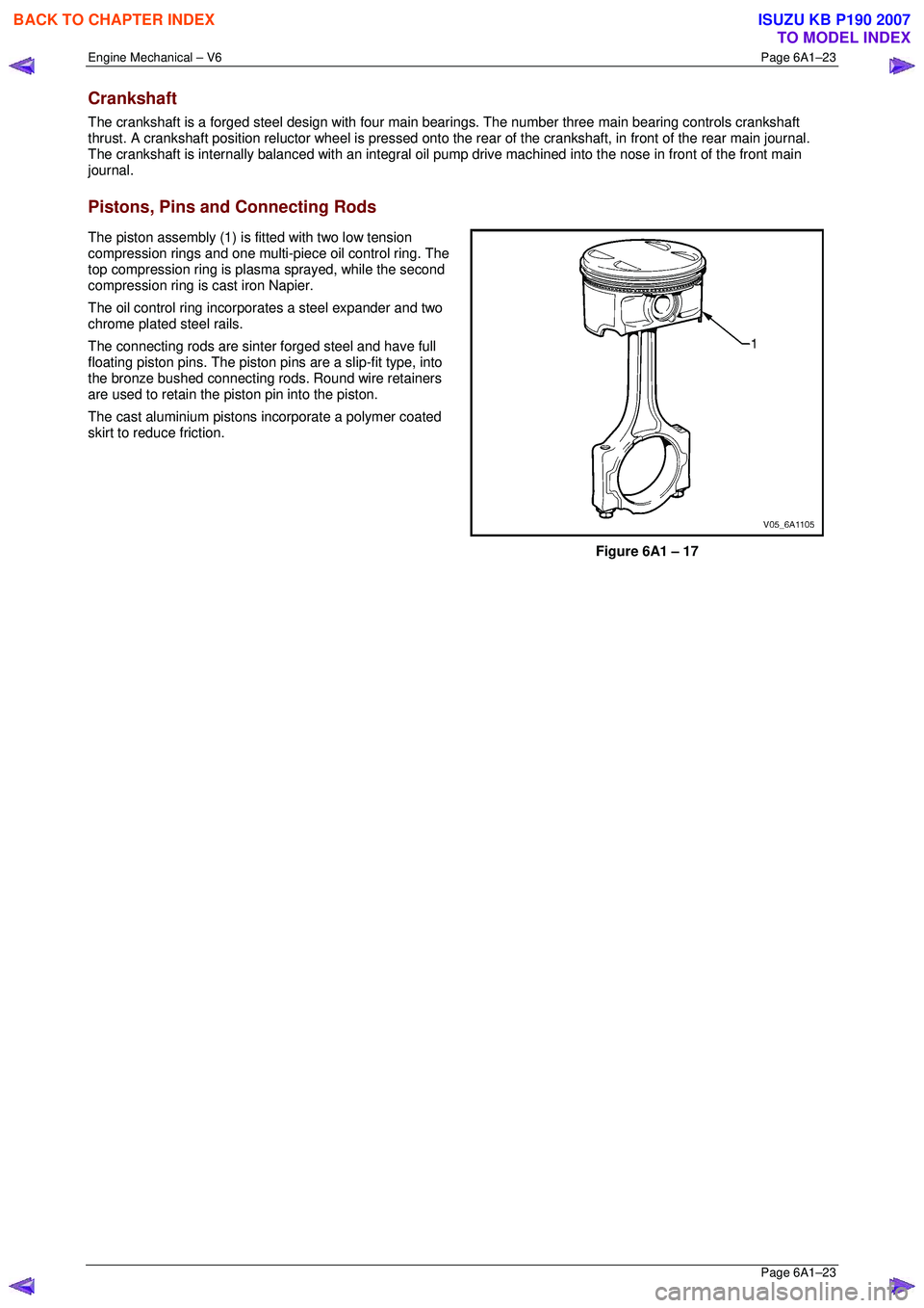
Pistons, Pins and Connecting Rods
The piston assembly (1) is fitted with two low tension
compression rings and one multi-piece oil control ring. The
top compression ring is plasma sprayed, while the second
compression ring is cast iron Napier.
The oil control ring incorpor ates a steel expander and two
chrome plated steel rails.
The connecting rods are sint er forged steel and have full
floating piston pins. The piston pi ns are a slip-fit type, into
the bronze bushed connecting rods. Round wire retainers
are used to retain the piston pin into the piston.
The cast aluminium pistons incorporate a polymer coated
skirt to reduce friction.
Figure 6A1 – 17
BACK TO CHAPTER INDEX
TO MODEL INDEX
ISUZU KB P190 2007
Page 2801 of 6020
Engine Mechanical – V6 Page 6A1–24
Page 6A1–24
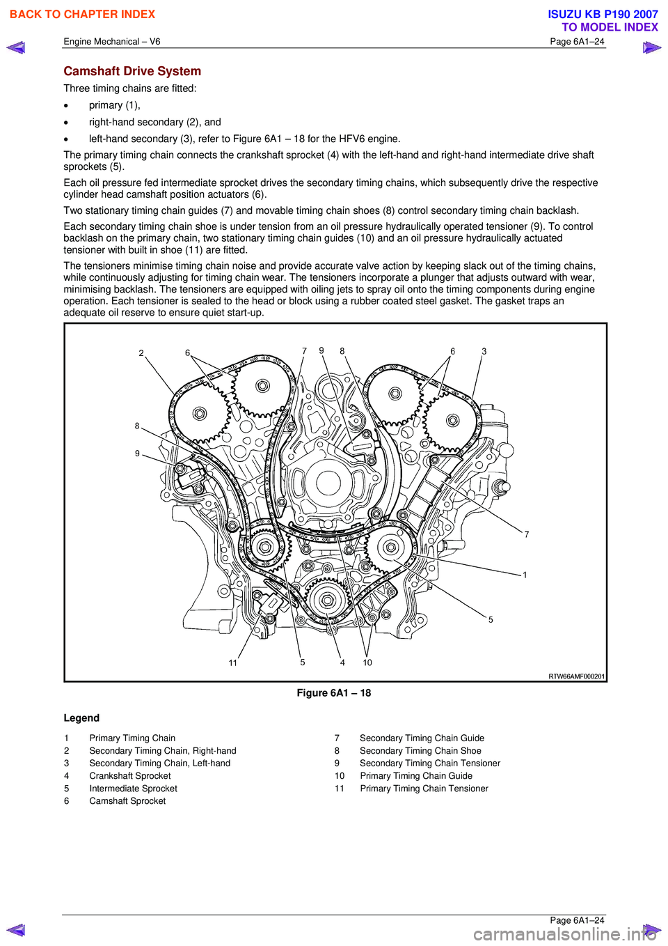
Camshaft Drive System
Three timing chains are fitted:
• primary (1),
• right-hand secondary (2), and
• left-hand secondary (3), refer to Figure 6A1 – 18 for the HFV6 engine.
The primary timing chain connects the crankshaft sprocket (4) with the left-hand and right-hand intermediate drive shaft
sprockets (5).
Each oil pressure fed intermediate sprocket drives the se condary timing chains, which subsequently drive the respective
cylinder head camshaft position actuators (6).
Two stationary timing chain guides (7) and movable timing c hain shoes (8) control secondary timing chain backlash.
Each secondary timing chain shoe is under tension from an oil pressure hydraulically operated tensioner (9). To control
backlash on the primary chain, two st ationary timing chain guides (10) and an oil pressure hydraulically actuated
tensioner with built in shoe (11) are fitted.
The tensioners minimise timing chain noise and provide accura te valve action by keeping slack out of the timing chains,
while continuously adjusting for timing chain wear. The tensioners incorporate a plunger that adjusts outward with wear,
minimising backlash. The tensioners are equipped with oiling jets to spray oil onto the timing components during engine
operation. Each tensioner is sealed to the head or block using a rubber coated steel gasket. The gasket traps an
adequate oil reserve to ens ure quiet start-up.
Figure 6A1 – 18
Legend
1 Primary Timing Chain
2 Secondary Timing Chain, Right-hand
3 Secondary Timing Chain, Left-hand
4 Crankshaft Sprocket
5 Intermediate Sprocket
6 Camshaft Sprocket 7 Secondary Timing Chain Guide
8 Secondary Timing Chain Shoe
9 Secondary Timing Chain Tensioner
10 Primary Timing Chain Guide
11 Primary Timing Chain Tensioner
BACK TO CHAPTER INDEX
TO MODEL INDEX
ISUZU KB P190 2007
Page 2802 of 6020
Engine Mechanical – V6 Page 6A1–25
Page 6A1–25
1.5 Engine Lubrication System
Lubrication Description
A structural diecast aluminium oil pan is fitted that incorporates an oil suction pipe, an oil deflector and an oil level
sensor. The oil suction pipe is bolted in to the oil pan and seals to the bottom of the cylinder block with a gasket. The oil
deflector is bolted to the upper portion of the oil pan and ensures oil supply is maintained under all conditions. The oil
level sensor is mounted thr ough the bottom of the oil pan.
A crankshaft driven gerotor oil pump is mounted to the front of the cylinder block. The pump, which incorporates an
internal pressure-relief valve, draws oil from the oil sucti on tube through the lower passage in the cylinder block. Oil is
then directed through an upper passage to the left-hand side of the cylinder block where the oil filter adapter is mounted.
The oil filter adapter incorporat es a top-access, cartridge style oil filter. The filter is accessed through a screw-on cap tha t
incorporates an oil bypass valve. The o il filter adapter housing incorporates a drain back control valve and a threaded oil
pressure sender. Oil flows through a lower passage within the oil filter adapter and through the o il filter cartridge. Filtered
oil travels back through the upper passage of the adapter and into the engine block.
Oil is then directed up and across the front of the cylinder block, through several drilled passages. These front passages
feed oil to each cylinder head, the passage for the main bearings and piston oil jets, the right-hand and left-hand
secondary idler sprockets and to t he primary timing chain tensioner.
Each cylinder head passage directs oil into oiling circuits for the stationary hydraulic la sh adjusters (SHLAs) and the
camshaft bearing journals. An additional passage in the cy linder head also directs oil to the secondary timing chain
tensioner.
The oil passage that supplies oil to the main bearings also s upplies oil to pressure actuated piston cooling oil jets. Each
oil jet is mounted between opposing cylinder bores and directs oil to the two bores to provide extra cooling and control
piston temperatures.
From the front passages, oil is directed to the front of the block where t he right-hand and left-hand intermediate drive
shaft sprockets and the primary timing chain tensioner are mounted. Each camshaft timing chain tensioner relies on a
gasket to maintain an oil rese rve after the engine is turned off. All camshaft timing chain tensioners incorporate a small
oil jet to supply an oil spray onto the camshaft timing chain components.
Oil returns to the oil pan, either through the camshaft timing chain area or through the drain back passages on the
outboard walls of the cylinder heads and cylinder block.
BACK TO CHAPTER INDEX
TO MODEL INDEX
ISUZU KB P190 2007