Page 2728 of 6020
Engine Mechanical – V6 Page 6A1–249
NOTE
Do not allow oil or other foreign material to
contact the outside diameter (OD) of the insert.
10 Lubricate the threads of the driver installation tool (2) with the driver oil (1).
Figure 6A1 – 474
11 Install the insert (2) onto the driver installation tool (1).
Figure 6A1 – 475
12 Apply thread lock sealant (1) such as Loctite 277® or equivalent to the insert OD threads (2).
Figure 6A1 – 476
BACK TO CHAPTER INDEX
TO MODEL INDEX
ISUZU KB P190 2007
Page 2730 of 6020

Engine Mechanical – V6 Page 6A1–251
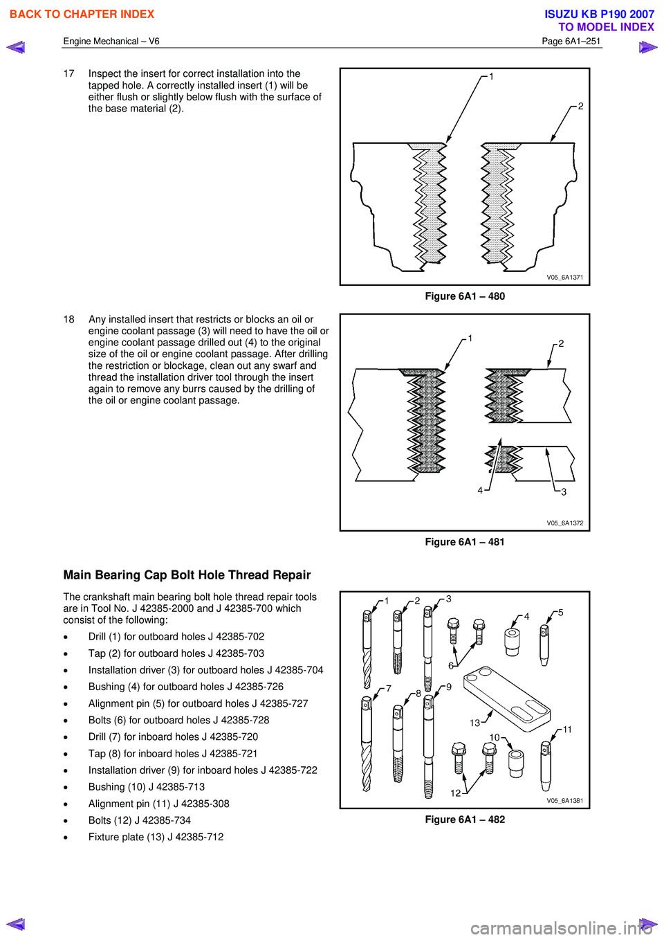
17 Inspect the insert for correct installation into the
tapped hole. A correctly installed insert (1) will be
either flush or slightly below flush with the surface of
the base material (2).
Figure 6A1 – 480
18 Any installed insert that restricts or blocks an oil or engine coolant passage (3) will need to have the oil or
engine coolant passage drilled out (4) to the original
size of the oil or engine coolant passage. After drilling
the restriction or blockage, clean out any swarf and
thread the installation driver tool through the insert
again to remove any burrs caused by the drilling of
the oil or engine coolant passage.
Figure 6A1 – 481
Main Bearing Cap Bolt Hole Thread Repair
The crankshaft main bearing bolt hole thread repair tools
are in Tool No. J 42385-2000 and J 42385-700 which
consist of the following:
• Drill (1) for outboard holes J 42385-702
• Tap (2) for outboard holes J 42385-703
• Installation driver (3) for outboard holes J 42385-704
• Bushing (4) for outboard holes J 42385-726
• Alignment pin (5) for outboard holes J 42385-727
• Bolts (6) for outboard holes J 42385-728
• Drill (7) for inboard holes J 42385-720
• Tap (8) for inboard holes J 42385-721
• Installation driver (9) for inboard holes J 42385-722
• Bushing (10) J 42385-713
• Alignment pin (11) J 42385-308
• Bolts (12) J 42385-734
• Fixture plate (13) J 42385-712
Figure 6A1 – 482
BACK TO CHAPTER INDEX
TO MODEL INDEX
ISUZU KB P190 2007
Page 2734 of 6020
Engine Mechanical – V6 Page 6A1–255
NOTE
All swarf must be removed from the tapped hole
prior to insert installation.
Safety glasses must be worn when using
compressed air.
12 Using compressed air, clean out any swarf.
Figure 6A1 – 491
NOTE
• Do not remove the fixture plate, ensure the
fixture plate is installed during the
installation process of the insert.
• Do not allow oil or other foreign material to
contact the outside diameter (OD) of the
insert.
13 Lubricate the threads of the driver installation tool (2) with the driver oil (1).
Figure 6A1 – 492
14 Install the insert (2) onto the driver installation tool (1).
Figure 6A1 – 493
BACK TO CHAPTER INDEX
TO MODEL INDEX
ISUZU KB P190 2007
Page 2740 of 6020
Engine Mechanical – V6 Page 6A1–261
NOTE
All swarf must be removed from the tapped hole
prior to insert installation.
Safety glasses must be worn when using
compressed air.
13 Using compressed air, clean out any swarf.
Figure 6A1 – 508
NOTE
Do not allow oil or other foreign material to
contact the outside diameter (OD) of the insert.
14 Lubricate the threads of the driver installation tool (2) with the driver oil (1).
Figure 6A1 – 509
15 Install the insert (2) onto the driver installation tool (1).
Figure 6A1 – 510
BACK TO CHAPTER INDEX
TO MODEL INDEX
ISUZU KB P190 2007
Page 2764 of 6020
Engine Mechanical – V6 Page 6A1–285
Oil Pan Front
Figure 6A1 – 536
Legend Hole Tool Number J 42385 Max. Depth in mm
Number Thread Size Drill Counter-
bore Tap Driver Insert Drill Tap
2 M8 x 1.25 206 207 208 209 210 28.5 23.0
3 M8 x 1.25 610 n/a 208 209 620 37.5 32.0
BACK TO CHAPTER INDEX
TO MODEL INDEX
ISUZU KB P190 2007
Page 2765 of 6020
Engine Mechanical – V6 Page 6A1–286
Oil Pan Rear
Figure 6A1 – 537
Legend Hole Tool Number J 42385 Max. Depth in mm
Number Thread Size Drill Counter-
bore Tap Driver Insert Drill Tap
1 M10 x 1.5 211 212 213 214 215 Thru Thru
BACK TO CHAPTER INDEX
TO MODEL INDEX
ISUZU KB P190 2007
Page 2766 of 6020
Engine Mechanical – V6 Page 6A1–287
Oil Pan Bottom
Figure 6A1 – 538
Legend Hole Tool Number J 42385 Max. Depth in mm
Number Thread Size Drill Counter-
bore Tap Driver Insert Drill Tap
1 M6 x 1.0 701 n/a 203 204 205 22.5 18.0
BACK TO CHAPTER INDEX
TO MODEL INDEX
ISUZU KB P190 2007
Page 2768 of 6020

Engine Mechanical – V6 Page 6A1–289
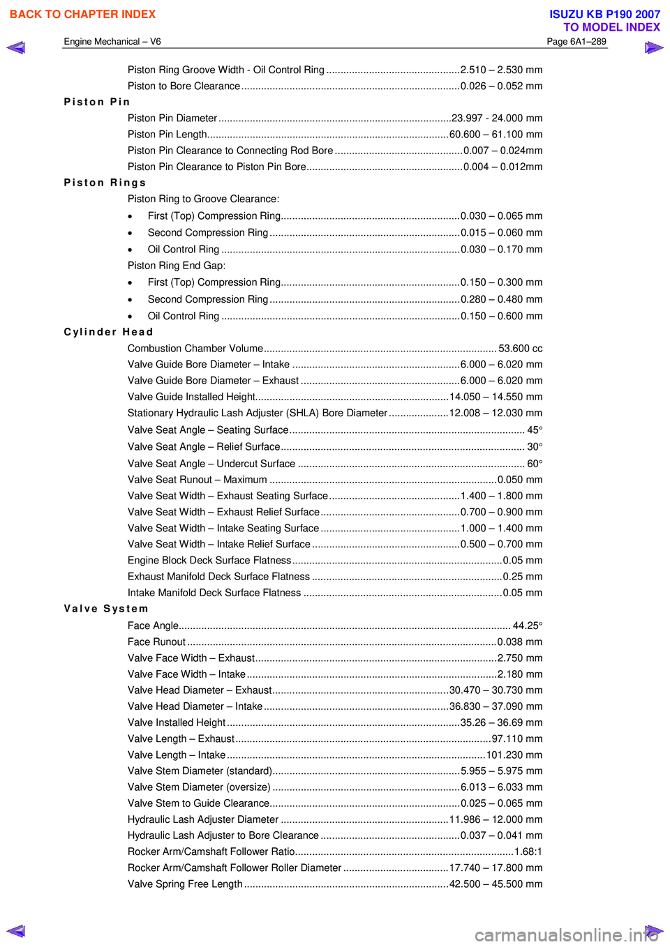
Piston Ring Groove Width - Oil Control Ring ............................................... 2.510 – 2.530 mm
Piston to Bore Clearance ............................................................................. 0.026 – 0.052 mm
Piston Pin
Piston Pin Diameter ..................................................................................23.997 - 24.000 mm
Piston Pin Length..................................................................................... 60.600 – 61.100 mm
Piston Pin Clearance to Connecting Rod Bore ............................................. 0.007 – 0.024mm
Piston Pin Clearance to Piston Pin Bore....................................................... 0.004 – 0.012mm
Piston Rings
Piston Ring to Groove Clearance:
• First (Top) Compression Ring............................................................... 0.030 – 0.065 mm
• Second Compression Ring ................................................................... 0.015 – 0.060 mm
• Oil Control Ring .................................................................................... 0.030 – 0.170 mm
Piston Ring End Gap:
• First (Top) Compression Ring............................................................... 0.150 – 0.300 mm
• Second Compression Ring ................................................................... 0.280 – 0.480 mm
• Oil Control Ring .................................................................................... 0.150 – 0.600 mm
Cylinder Head
Combustion Chamber Volume.................................................................................. 53.600 cc
Valve Guide Bore Diameter – Intake ........................................................... 6.000 – 6.020 mm
Valve Guide Bore Diameter – Exhaust ........................................................ 6.000 – 6.020 mm
Valve Guide Installed Height.................................................................... 14.050 – 14.550 mm
Stationary Hydraulic Lash Adjuster (SHLA) Bore Diameter ..................... 12.008 – 12.030 mm
Valve Seat Angle – Seating Surface ................................................................................... 45 °
Valve Seat Angle – Relief Surface ...................................................................................... 30 °
Valve Seat Angle – Undercut Surface ................................................................................ 60 °
Valve Seat Runout – Maximum ................................................................................ 0.050 mm
Valve Seat Width – Exhaust Seating Surface .............................................. 1.400 – 1.800 mm
Valve Seat Width – Exhaust Relief Surface ................................................. 0.700 – 0.900 mm
Valve Seat Width – Intake Seating Surface ................................................. 1.000 – 1.400 mm
Valve Seat Width – Intake Relief Surface .................................................... 0.500 – 0.700 mm
Engine Block Deck Surface Flatness .......................................................................... 0.05 mm
Exhaust Manifold Deck Surface Flatness ................................................................... 0.25 mm
Intake Manifold Deck Surface Flatness ...................................................................... 0.05 mm
Valve System
Face Angle..................................................................................................................... 44.25°
Face Runout ............................................................................................................. 0.038 m m
Valve Face Width – Exhaust..................................................................................... 2.750 mm
Valve Face Width – Intake ........................................................................................ 2.180 mm
Valve Head Diameter – Exhaust .............................................................. 30.470 – 30.730 mm
Valve Head Diameter – Intake ................................................................. 36.830 – 37.090 mm
Valve Installed Height .................................................................................. 35.26 – 36.69 mm
Valve Length – Exhaust .......................................................................................... 97.110 mm
Valve Length – Intake ........................................................................................... 101.230 mm
Valve Stem Diameter (standard).................................................................. 5.955 – 5.975 mm
Valve Stem Diameter (oversize) .................................................................. 6.013 – 6.033 mm
Valve Stem to Guide Clearance................................................................... 0.025 – 0.065 mm
Hydraulic Lash Adjuster Diameter ........................................................... 11.986 – 12.000 mm
Hydraulic Lash Adjuster to Bore Clearance ................................................. 0.037 – 0.041 mm
Rocker Arm/Camshaft Follower Ratio............................................................................. 1.68:1
Rocker Arm/Camshaft Follower Roller Diameter ..................................... 17.740 – 17.800 mm
Valve Spring Free Length ........................................................................ 42.500 – 45.500 mm
BACK TO CHAPTER INDEX
TO MODEL INDEX
ISUZU KB P190 2007