Page 2684 of 6020

Engine Mechanical – V6 Page 6A1–205
Reinstall
NOTE
The bolt holes are unevenly spaced to enable
flexplate fitment in the one position only.
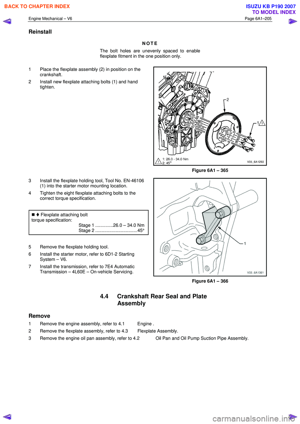
1 Place the flexplate assembly (2) in position on the crankshaft.
2 Install new flexplate attaching bolts (1) and hand tighten.
Figure 6A1 – 365
3 Install the flexplate holding tool, Tool No. EN-46106 (1) into the starter motor mounting location.
4 Tighten the eight flexplate attaching bolts to the correct torque specification.
�„ Flexplate attaching bolt
torque specification:
Stage 1 ..............26.0 – 34.0 Nm
Stage 2 ................................. 45°
5 Remove the flexplate holding tool.
6 Install the starter motor, refer to 6D1-2 Starting System – V6.
7 Install the transmission, refer to 7E4 Automatic Transmission – 4L60E – On-vehicle Servicing.
Figure 6A1 – 366
4.4 Crankshaft Rear Seal and Plate Assembly
Remove
1 Remove the engine assembly, refer to 4.1 Engine .
2 Remove the flexplate assembly, refer to 4.3 Flexplate Assembly.
3 Remove the engine oil pan assembly, refer to 4.2 Oil Pan and Oil Pump Suction Pipe Assembly.
BACK TO CHAPTER INDEX
TO MODEL INDEX
ISUZU KB P190 2007
Page 2685 of 6020
Engine Mechanical – V6 Page 6A1–206
4 Remove the five bolts (1) attaching the crankshaft
rear seal housing to the rear of the cylinder block (2).
Figure 6A1 – 367
5 Shear the RTV sealant using the prise points located at the edge of the crankshaft rear oil seal housing,
Figure 6A1 – 368
6 Remove the crankshaft rear oil seal housing (1) from the cylinder block (2).
Figure 6A1 – 369
BACK TO CHAPTER INDEX
TO MODEL INDEX
ISUZU KB P190 2007
Page 2686 of 6020
Engine Mechanical – V6 Page 6A1–207
Reinstall
1 Install the guide pins, Tool No. EN-46109 (1) into the
two crankshaft rear oil seal housing bolt holes of the
cylinder block (2).
Figure 6A1 – 370
2 Apply a 3mm bead (1) of RTV sealant to the crankshaft rear oil seal housing.
Figure 6A1 – 371
3 Install the crankshaft rear oil seal housing (1) to the cylinder block (2).
NOTE
• Do not allow any engine oil onto the cylinder
block mating surface, where the crankshaft
rear oil seal housing is to be installed.
• A seal-protector is provided with the new
crankshaft rear seal and housing assembly.
Do not remove the seal protector from the
crankshaft rear oil seal housing until the
crankshaft rear oil seal housing is fully in
position.
4 Remove the guide pins from the cylinder block.
Figure 6A1 – 372
BACK TO CHAPTER INDEX
TO MODEL INDEX
ISUZU KB P190 2007
Page 2687 of 6020

Engine Mechanical – V6 Page 6A1–208
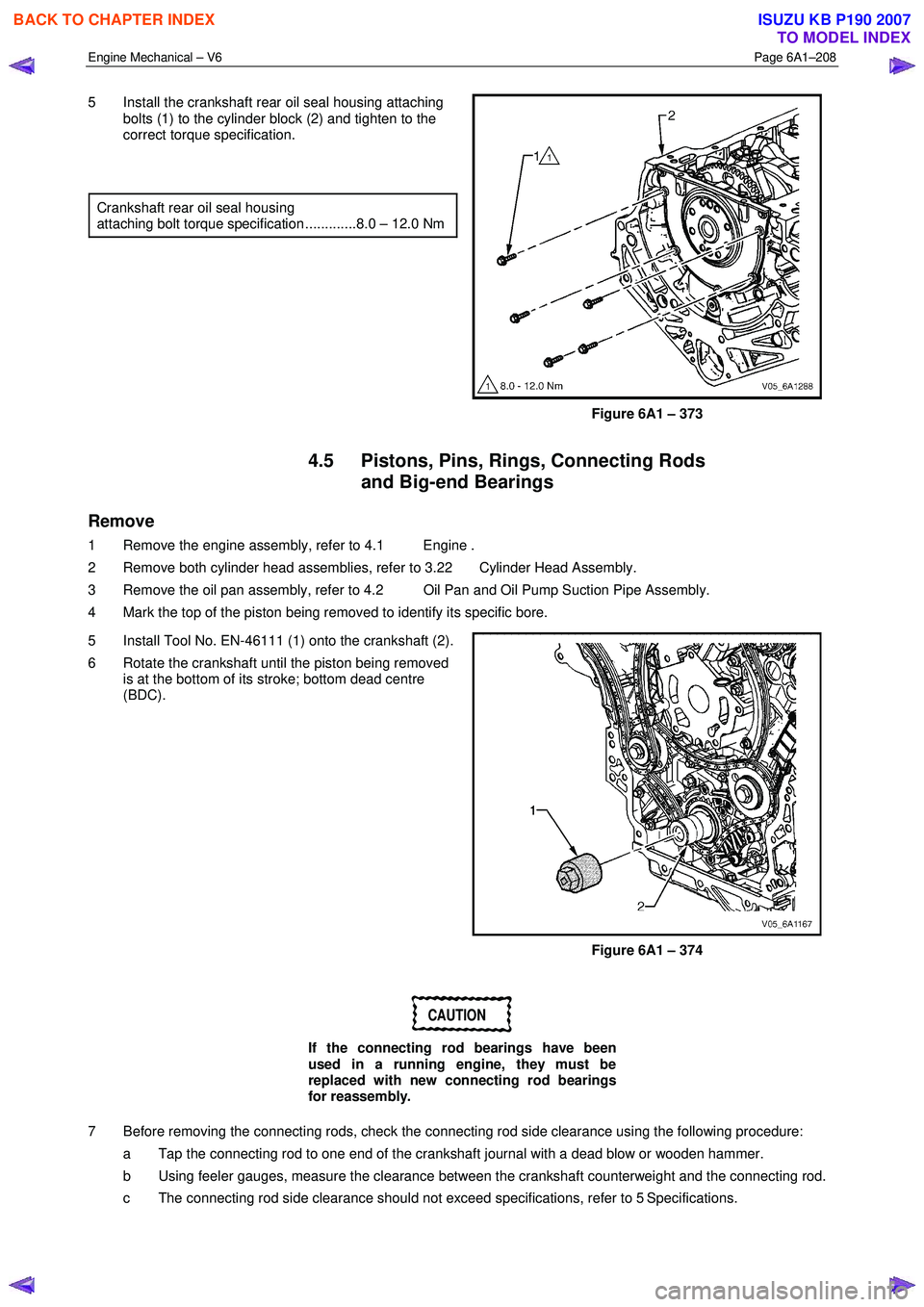
5 Install the crankshaft rear oil seal housing attaching
bolts (1) to the cylinder block (2) and tighten to the
correct torque specification.
Crankshaft rear oil seal housing
attaching bolt torque specification .............8.0 – 12.0 Nm
Figure 6A1 – 373
4.5 Pistons, Pins, Rings, Connecting Rods and Big-end Bearings
Remove
1 Remove the engine assembly, refer to 4.1 Engine .
2 Remove both cylinder head assemblies, refer to 3.22 Cylinder Head Assembly.
3 Remove the oil pan assembly, refer to 4.2 Oil Pan and Oil Pump Suction Pipe Assembly.
4 Mark the top of the piston being removed to identify its specific bore.
5 Install Tool No. EN-46111 (1) onto the crankshaft (2).
6 Rotate the crankshaft until the piston being removed is at the bottom of its stroke; bottom dead centre
(BDC).
Figure 6A1 – 374
CAUTION
If the connecting rod bearings have been
used in a running engine, they must be
replaced with new connecting rod bearings
for reassembly.
7 Before removing the connecting rods, check the connecting rod side clearance using the following procedure: a Tap the connecting rod to one end of the crankshaft journal with a dead blow or wooden hammer.
b Using feeler gauges, measure the clearance between the crankshaft counterweight and the connecting rod.
c The connecting rod side clearance should not exceed specifications, refer to 5 Specifications.
BACK TO CHAPTER INDEX
TO MODEL INDEX
ISUZU KB P190 2007
Page 2691 of 6020
Engine Mechanical – V6 Page 6A1–212
CAUTION
Do not reuse the piston pin retainers.
2 Remove the piston pin retainers by using the removal access notch (1) in the side of the piston. Discard the
piston pin retainers.
Figure 6A1 – 382
3 Slide the piston pin (1) out of the piston (2). The piston will disconnect from the connecting rod.
Figure 6A1 – 383
Clean and Inspect
Piston Cleaning Procedure
CAUTION
Do not use a wire brush to clean any part of
the piston.
1 Clean the piston skirts and the pins with a suitable solvent.
2 Clean the piston ring grooves with a groove cleaner. Ensure the oil ring holes and slots are clean.
Safety glasses must be worn when using
compressed air.
3 Dry the piston with compressed air.
BACK TO CHAPTER INDEX
TO MODEL INDEX
ISUZU KB P190 2007
Page 2696 of 6020
Engine Mechanical – V6 Page 6A1–217
Reassemble
Piston and Piston Pin
CAUTION
The arrow located on top of the piston must
point toward the front of the engine.
NOTE
The connecting rod is non-directional and may
be assembled/reassembled to the piston in
either direction.
1 Lubricate the piston pin (1) bores in the piston (2) and the connecting rod with clean engine oil.
2 Assemble the piston and piston pin to the connecting rod. Correctly orient the piston when reusing a
marked connecting rod.
3 Align the piston pin bore with the connecting rod pin bore.
4 Slide the piston pin into the piston and the connecting rod.
Figure 6A1 – 395
CAUTION
New piston pin retainers must be used.
Never reuse the piston pin retainers.
5 Install new piston pin retainers (1).
6 Ensure the piston pin retainers are fully seated in their grooves.
7 Repeat steps 1 to 6 for the remaining pistons.
Figure 6A1 – 396
BACK TO CHAPTER INDEX
TO MODEL INDEX
ISUZU KB P190 2007
Page 2697 of 6020
Engine Mechanical – V6 Page 6A1–218
Piston Ring
NOTE
The ends of the expander must be facing
toward the top of the piston.
1 Correctly orient the oil control ring expander (1) before installation.
Figure 6A1 – 397
2 Using a piston ring expander, install the oil control ring assembly using the following procedure:
3 Install the expander ring (3).
4 Install the two oil scraper rings (4). Expand the rings only enough to clear the piston diameter. Over-
expanding the piston rings will distort or crack the
rings.
5 Install the second (2) and top (1) piston rings as follows.
Figure 6A1 – 398
6 Using the ring expander (1), install the second piston ring (2) onto the piston (3). Do not over-expand the
ring. Repeat for the top ring.
Figure 6A1 – 399
BACK TO CHAPTER INDEX
TO MODEL INDEX
ISUZU KB P190 2007
Page 2698 of 6020

Engine Mechanical – V6 Page 6A1–219
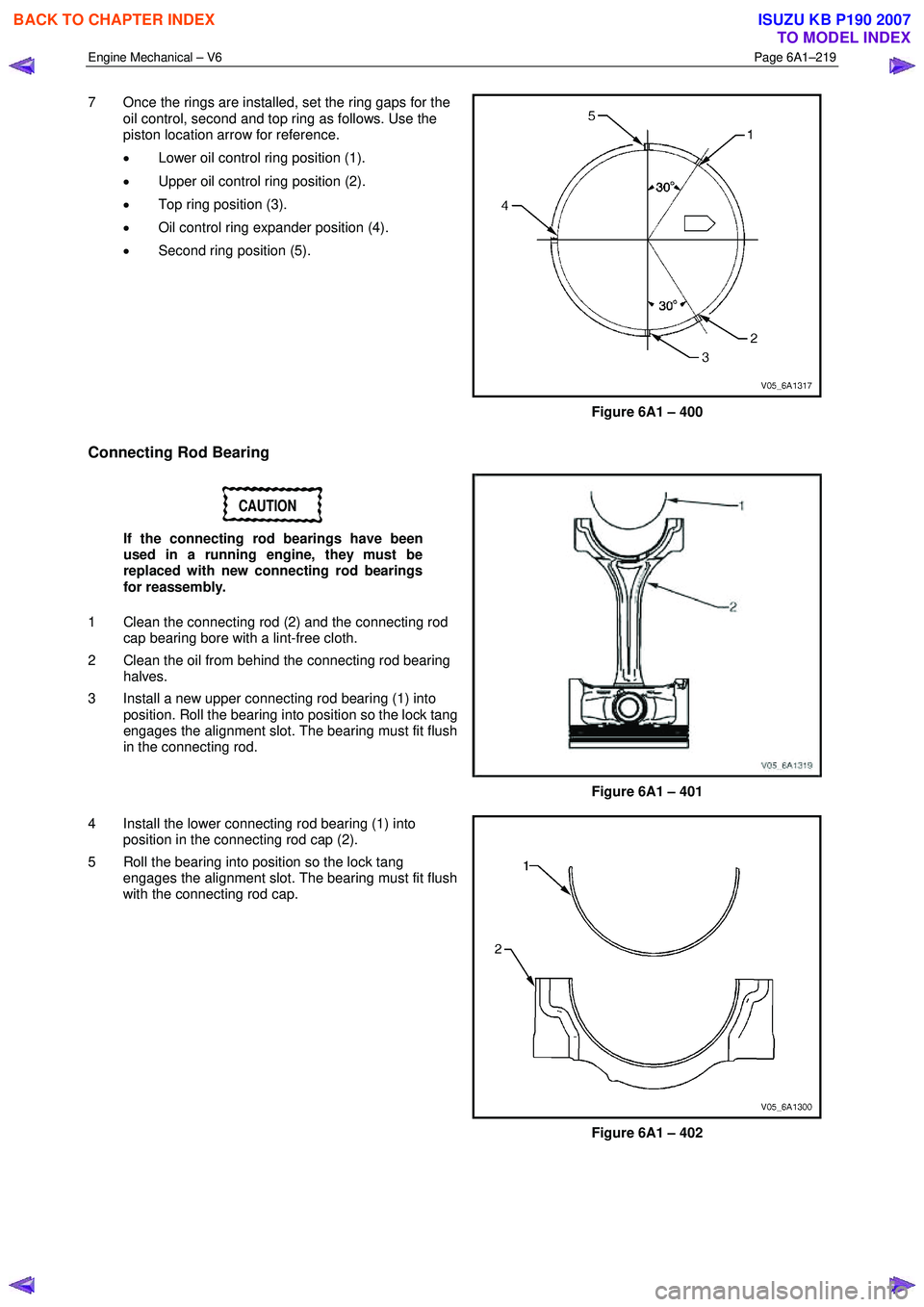
7 Once the rings are installed, set the ring gaps for the
oil control, second and top ring as follows. Use the
piston location arrow for reference.
• Lower oil control ring position (1).
• Upper oil control ring position (2).
• Top ring position (3).
• Oil control ring expander position (4).
• Second ring position (5).
Figure 6A1 – 400
Connecting Rod Bearing
CAUTION
If the connecting rod bearings have been
used in a running engine, they must be
replaced with new connecting rod bearings
for reassembly.
1 Clean the connecting rod (2) and the connecting rod cap bearing bore with a lint-free cloth.
2 Clean the oil from behind the connecting rod bearing halves.
3 Install a new upper connecting rod bearing (1) into position. Roll the bearing into position so the lock tang
engages the alignment slot. The bearing must fit flush
in the connecting rod.
Figure 6A1 – 401
4 Install the lower connecting rod bearing (1) into position in the connecting rod cap (2).
5 Roll the bearing into position so the lock tang engages the alignment slot. The bearing must fit flush
with the connecting rod cap.
Figure 6A1 – 402
BACK TO CHAPTER INDEX
TO MODEL INDEX
ISUZU KB P190 2007