2007 ISUZU KB P190 engine oil
[x] Cancel search: engine oilPage 2640 of 6020
Engine Mechanical – V6 Page 6A1–161
Reinstall
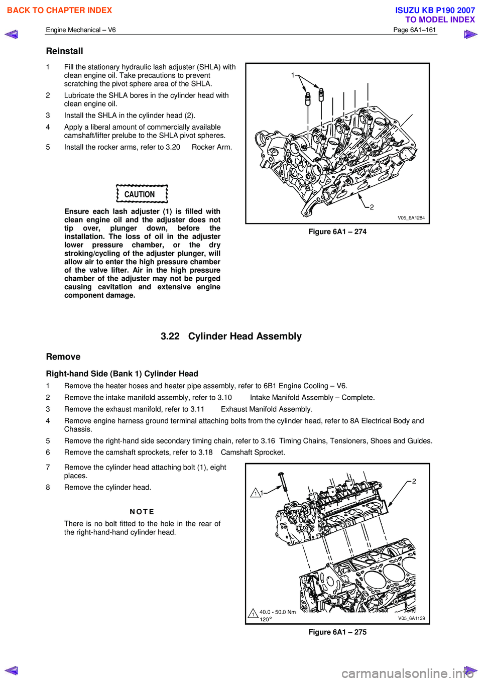
1 Fill the stationary hydraulic lash adjuster (SHLA) with
clean engine oil. Take precautions to prevent
scratching the pivot sphere area of the SHLA.
2 Lubricate the SHLA bores in the cylinder head with clean engine oil.
3 Install the SHLA in the cylinder head (2).
4 Apply a liberal amount of commercially available camshaft/lifter prelube to the SHLA pivot spheres.
5 Install the rocker arms, refer to 3.20 Rocker Arm.
CAUTION
Ensure each lash adjuster (1) is filled with
clean engine oil and the adjuster does not
tip over, plunger down, before the
installation. The loss of oil in the adjuster
lower pressure chamber, or the dry
stroking/cycling of the adjuster plunger, will
allow air to enter the high pressure chamber
of the valve lifter. Air in the high pressure
chamber of the adjuster may not be purged
causing cavitation and extensive engine
component damage.
Figure 6A1 – 274
3.22 Cylinder Head Assembly
Remove
Right-hand Side (Bank 1) Cylinder Head
1 Remove the heater hoses and heater pipe assembly, refer to 6B1 Engine Cooling – V6.
2 Remove the intake manifold assembly, refer to 3.10 Intake Manifold Assembly – Complete.
3 Remove the exhaust manifold, refer to 3.11 Exhaust Manifold Assembly.
4 Remove engine harness ground terminal attaching bolts from the cylinder head, refer to 8A Electrical Body and Chassis.
5 Remove the right-hand side secondary timing chain, refer to 3.16 Timing Chains, Tensioners, Shoes and Guides.
6 Remove the camshaft sprockets, refer to 3.18 Camshaft Sprocket.
7 Remove the cylinder head attaching bolt (1), eight places.
8 Remove the cylinder head.
NOTE
There is no bolt fitted to the hole in the rear of
the right-hand-hand cylinder head.
Figure 6A1 – 275
BACK TO CHAPTER INDEX
TO MODEL INDEX
ISUZU KB P190 2007
Page 2641 of 6020
Engine Mechanical – V6 Page 6A1–162
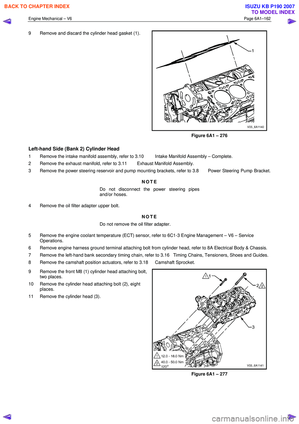
9 Remove and discard the cylinder head gasket (1).
Figure 6A1 – 276
Left-hand Side (Bank 2) Cylinder Head
1 Remove the intake manifold assembly, refer to 3.10 Intake Manifold Assembly – Complete.
2 Remove the exhaust manifold, refer to 3.11 Exhaust Manifold Assembly.
3 Remove the power steering reservoir and pump mounting brackets, refer to 3.8 Power Steering Pump Bracket.
NOTE
Do not disconnect the power steering pipes
and/or hoses.
4 Remove the oil filter adapter upper bolt. NOTE
Do not remove the oil filter adapter.
5 Remove the engine coolant temperature (ECT) sensor, refer to 6C1-3 Engine Management – V6 – Service Operations.
6 Remove engine harness ground terminal attaching bolt from cylinder head, refer to 8A Electrical Body & Chassis.
7 Remove the left-hand bank secondary timing chain, refer to 3.16 Timing Chains, Tensioners, Shoes and Guides.
8 Remove the camshaft position actuators, refer to 3.18 Camshaft Sprocket.
9 Remove the front M8 (1) cylinder head attaching bolt, two places.
10 Remove the cylinder head attaching bolt (2), eight places.
11 Remove the cylinder head (3).
Figure 6A1 – 277
BACK TO CHAPTER INDEX
TO MODEL INDEX
ISUZU KB P190 2007
Page 2643 of 6020
Engine Mechanical – V6 Page 6A1–164
CAUTION
Do not compress the valve springs less than
24.0 mm. Contact between the valve spring
retainer and the valve stem oil seal can
cause potential valve stem oil seal damage.
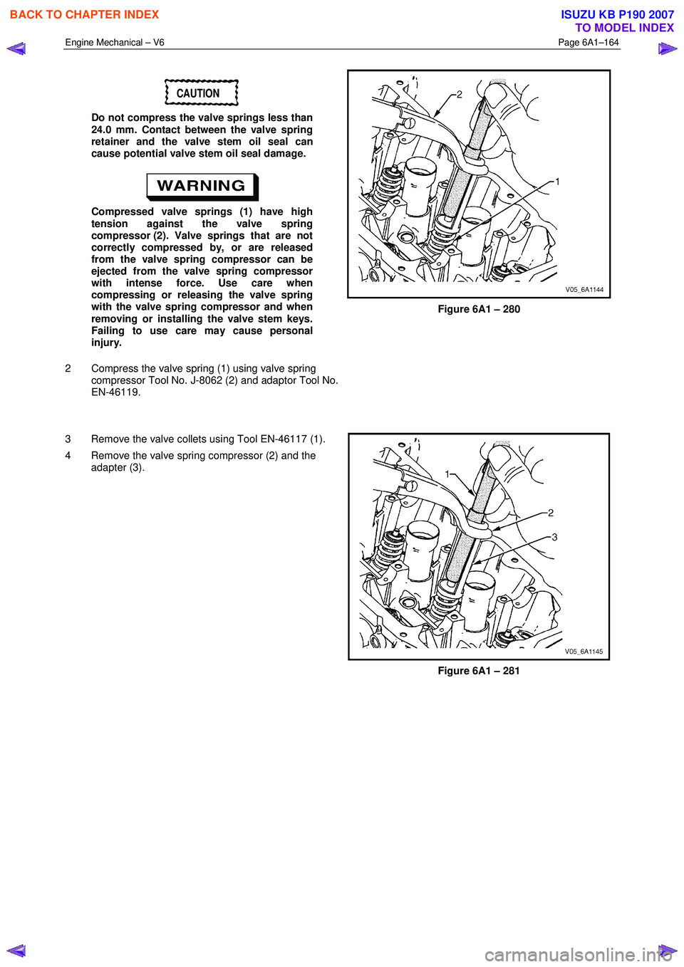
Compressed valve springs (1) have high
tension against the valve spring
compressor (2). Valve springs that are not
correctly compressed by, or are released
from the valve spring compressor can be
ejected from the valve spring compressor
with intense force. Use care when
compressing or releasing the valve spring
with the valve spring compressor and when
removing or installing the valve stem keys.
Failing to use care may cause personal
injury.
2 Compress the valve spring (1) using valve spring compressor Tool No. J-8062 (2) and adaptor Tool No.
EN-46119.
Figure 6A1 – 280
3 Remove the valve collets using Tool EN-46117 (1).
4 Remove the valve spring compressor (2) and the adapter (3).
Figure 6A1 – 281
BACK TO CHAPTER INDEX
TO MODEL INDEX
ISUZU KB P190 2007
Page 2644 of 6020
Engine Mechanical – V6 Page 6A1–165
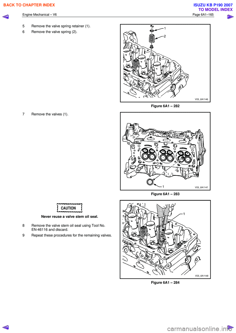
5 Remove the valve spring retainer (1).
6 Remove the valve spring (2).
Figure 6A1 – 282
7 Remove the valves (1).
Figure 6A1 – 283
CAUTION
Never reuse a valve stem oil seal.
8 Remove the valve stem oil seal using Tool No. EN-46116 and discard.
9 Repeat these procedures for the remaining valves.
Figure 6A1 – 284
BACK TO CHAPTER INDEX
TO MODEL INDEX
ISUZU KB P190 2007
Page 2645 of 6020
Engine Mechanical – V6 Page 6A1–166
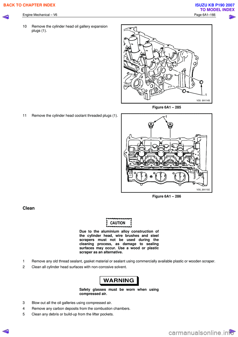
10 Remove the cylinder head oil gallery expansion
plugs (1).
Figure 6A1 – 285
11 Remove the cylinder head coolant threaded plugs (1).
Figure 6A1 – 286
Clean
CAUTION
Due to the aluminium alloy construction of
the cylinder head, wire brushes and steel
scrapers must not be used during the
cleaning process, as damage to sealing
surfaces may occur. Use a wood or plastic
scraper as an alternative.
1 Remove any old thread sealant, gasket material or sealant using commercially available plastic or wooden scraper.
2 Clean all cylinder head surfaces with non-corrosive solvent.
Safety glasses must be worn when using
compressed air.
3 Blow out all the oil galleries using compressed air.
4 Remove any carbon deposits from the combustion chambers.
5 Clean any debris or build-up from the lifter pockets.
BACK TO CHAPTER INDEX
TO MODEL INDEX
ISUZU KB P190 2007
Page 2646 of 6020
Engine Mechanical – V6 Page 6A1–167
Inspect
Visual Inspection
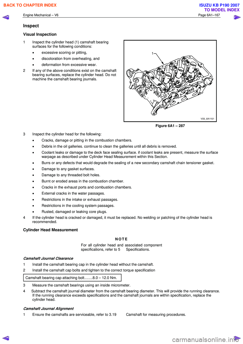
1 Inspect the cylinder head (1) camshaft bearing
surfaces for the following conditions:
• excessive scoring or pitting,
• discoloration from overheating, and
• deformation from excessive wear.
2 If any of the above conditions exist on the camshaft bearing surfaces, replace the cylinder head. Do not
machine the camshaft bearing journals.
Figure 6A1 – 287
3 Inspect the cylinder head for the following: • Cracks, damage or pitting in the combustion chambers.
• Debris in the oil galleries. continue to clean the galleries until all debris is removed.
• Coolant leaks or damage to the deck face sealing surface. if coolant leaks are present, measure the surface
warpage as described under Cylinder Head Measurement within this Section.
• Burrs or any defects that would degrade the sealing of a new secondary camshaft chain tensioner gasket.
• Damage to any gasket surfaces.
• Damage to any threaded bolt holes.
• Burnt or eroded areas in the combustion chamber.
• Cracks in the exhaust ports and combustion chambers.
• External cracks in the water passages.
• Restrictions in the intake or exhaust passages.
• Restrictions in the cooling system passages.
• Rusted, damaged or leaking core plugs.
4 If the cylinder head is cracked or damaged, it must be replaced. No welding or patching of the cylinder head is recommended.
Cylinder Head Measurement
NOTE
For all cylinder head and associated component
specifications, refer to 5 Specifications.
Camshaft Journal Clearance
1 Install the camshaft bearing cap in the cylinder head without the camshaft.
2 Install the camshaft cap bolts and tighten to the correct torque specification
Camshaft bearing cap attaching bolt........8.0 – 12.0 Nm.
3 Measure the camshaft bearings using an inside micrometer.
4 Subtract the camshaft journal diameter from the camshaft bearing diameter. This will provide the running clearance. If the running clearance exceeds specifications and the camshaft journals are within specification, replace the
cylinder head.
Camshaft Journal Alignment
1 Ensure the camshafts are serviceable, refer to 3.19 Camshaft for measuring procedures.
BACK TO CHAPTER INDEX
TO MODEL INDEX
ISUZU KB P190 2007
Page 2648 of 6020
Engine Mechanical – V6 Page 6A1–169
Valve Guide Measurement
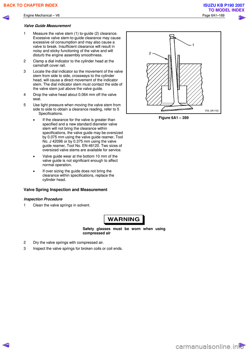
1 Measure the valve stem (1) to-guide (2) clearance.
Excessive valve stem-to-guide clearance may cause
excessive oil consumption and may also cause a
valve to break. Insufficient clearance will result in
noisy and sticky functioning of the valve and will
disturb the engine assembly smoothness.
2 Clamp a dial indicator to the cylinder head at the camshaft cover rail.
3 Locate the dial indicator so the movement of the valve stem from side to side, crossways to the cylinder
head, will cause a direct movement of the indicator
stem. The dial indicator stem must contact the side of
the valve stem just above the valve guide.
4 Drop the valve head about 0.064 mm off the valve seat.
5 Use light pressure when moving the valve stem from side to side to obtain a clearance reading, refer to 5
Specifications.
• If the clearance for the valve is greater than
specified and a new standard diameter valve
stem will not bring the clearance within
specifications, the valve guide may be oversized
by 0.075 mm using the valve guide reamer, Tool
No. J 42096 or by 0.375 mm using the valve
guide reamer, Tool No. EN-46120. Two sizes of
oversized valve stems are available for service.
• Valve guide wear at the bottom 10 mm of the
valve guide is not significant enough to affect
normal operation.
• If over sizing the guide does not bring the
clearance within specifications, replace the
cylinder head.
Figure 6A1 – 289
Valve Spring Inspection and Measurement
Inspection Procedure
1 Clean the valve springs in solvent.
Safety glasses must be worn when using
compressed air
2 Dry the valve springs with compressed air.
3 Inspect the valve springs for broken coils or coil ends.
BACK TO CHAPTER INDEX
TO MODEL INDEX
ISUZU KB P190 2007
Page 2653 of 6020
Engine Mechanical – V6 Page 6A1–174
Valve Stem Height Measurement Procedure
CAUTION
To determine the valve stem height
measurement, measure from the valve
spring seat to the valve spring retainer.
1 Install the valve into the valve guide.
2 Ensure the valve is seated to the valve seat.
3 Install the valve stem oil seal.
4 Install the valve spring retainer and valve stem keys.
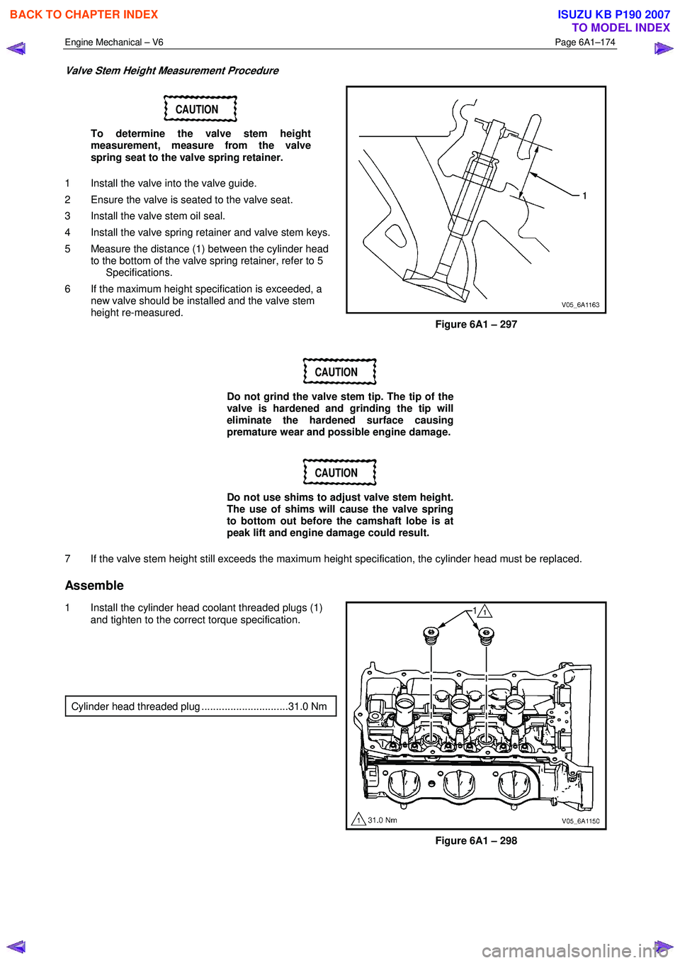
5 Measure the distance (1) between the cylinder head to the bottom of the valve spring retainer, refer to 5
Specifications.
6 If the maximum height specification is exceeded, a new valve should be installed and the valve stem
height re-measured.
Figure 6A1 – 297
CAUTION
Do not grind the valve stem tip. The tip of the
valve is hardened and grinding the tip will
eliminate the hardened surface causing
premature wear and possible engine damage.
CAUTION
Do not use shims to adjust valve stem height.
The use of shims will cause the valve spring
to bottom out before the camshaft lobe is at
peak lift and engine damage could result.
7 If the valve stem height still exceeds the maximum height specification, the cylinder head must be replaced.
Assemble
1 Install the cylinder head coolant threaded plugs (1) and tighten to the correct torque specification.
Cylinder head threaded plug ..............................31.0 Nm
Figure 6A1 – 298
BACK TO CHAPTER INDEX
TO MODEL INDEX
ISUZU KB P190 2007