2007 ISUZU KB P190 trans
[x] Cancel search: transPage 1078 of 6020
6E-44 Engine Control System (4JH1)
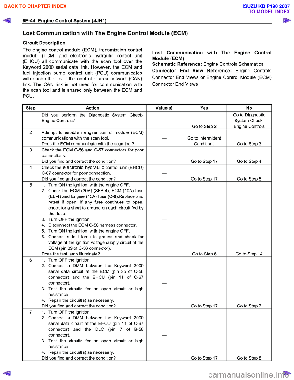
Lost Communication with The Engine Control Module (ECM)
Circuit Description
The engine control module (ECM), transmission control
module (TCM) and electronic hydraulic control unit
(EHCU) all communicate with the scan tool over the
Keyword 2000 serial data link. However, the ECM and
fuel injection pump control unit (PCU) communicates
with each other over the controller area network (CAN)
link. The CAN link is not used for communication with
the scan tool and is shared only between the ECM and
PCU.
Lost Communication with The Engine Control
Module (ECM)
Schematic Reference: Engine Controls Schematics
Connector End View Reference: Engine Controls
Connector End Views or Engine Control Module (ECM)
Connector End Views
Step Action Value(s) Yes No
1 Did you perform the Diagnostic System Check-
Engine Controls?
Go to Step 2 Go to Diagnostic
System Check-
Engine Controls
2 Attempt to establish engine control module (ECM) communications with the scan tool.
Does the ECM communicate with the scan tool?
Go to Intermittent
Conditions Go to Step 3
3 Check the ECM C-56 and C-57 connectors for poor connections.
Did you find and correct the condition?
Go to Step 17 Go to Step 4
4 Check the electronic hydraulic control unit (EHCU)
C-67 connector for poor connection.
Did you find and correct the condition?
Go to Step 17 Go to Step 5
5 1. Turn ON the ignition, with the engine OFF. 2. Check the ECM (30A) (SFB-4), ECM (10A) fuse (EB-4) and Engine (15A) fuse (C-6).Replace and
retest if open. If any fuse continues to open,
check for a short to ground on each circuit fed by
that fuse.
3. Turn OFF the ignition.
4. Disconnect the ECM C-56 harness connector.
5. Turn ON the ignition, with the engine OFF.
6. Connect a test lamp to ground and check for voltage at the ignition voltage supply circuit at the
ECM (pin 39 of C-56 connector).
Does the test lamp illuminate?
Go to Step 6 Go to Step 14
6 1. Turn OFF the ignition. 2. Connect a DMM between the Keyword 2000 serial data circuit at the ECM (pin 35 of C-56
connector) and the EHCU (pin 11 of C-67
connector).
3. Test the circuits for an open circuit or high resistance.
4. Repair the circuit(s) as necessary.
Did you find and correct the condition?
Go to Step 17 Go to Step 7
7 1. Turn OFF the ignition. 2. Connect a DMM between the Keyword 2000 serial data circuit at the EHCU (pin 11 of C-67
connector) and the DLC (pin 7 of B-58
connector).
3. Test the circuits for an open circuit or high resistance.
4. Repair the circuit(s) as necessary.
Did you find and correct the condition?
Go to Step 17 Go to Step 8
BACK TO CHAPTER INDEX
TO MODEL INDEX
ISUZU KB P190 2007
Page 1079 of 6020
Engine Control System (4JH1) 6E-45
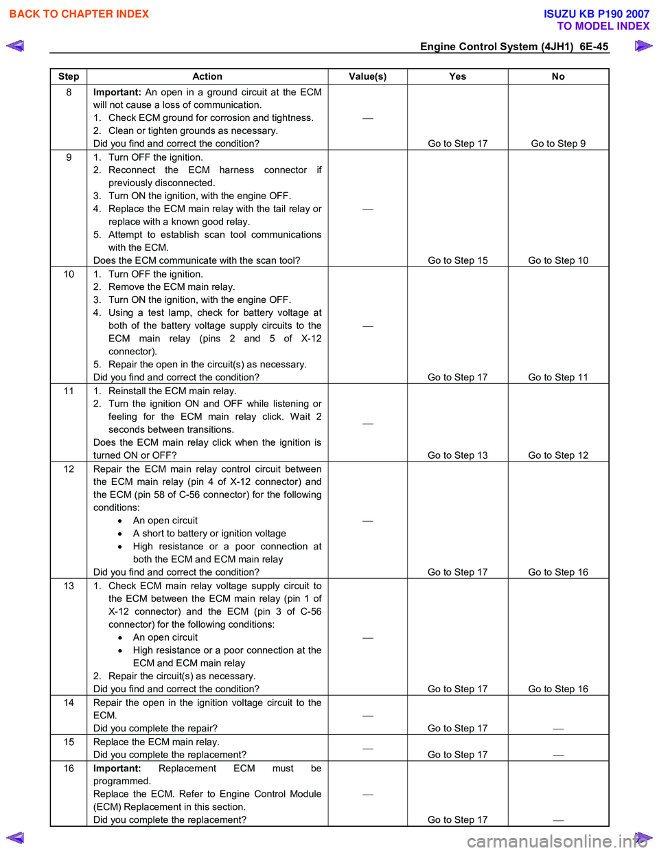
Step Action Value(s) Yes No
8 Important: An open in a ground circuit at the ECM
will not cause a loss of communication.
1. Check ECM ground for corrosion and tightness.
2. Clean or tighten grounds as necessary.
Did you find and correct the condition?
Go to Step 17 Go to Step 9
9 1. Turn OFF the ignition. 2. Reconnect the ECM harness connector if previously disconnected.
3. Turn ON the ignition, with the engine OFF.
4. Replace the ECM main relay with the tail relay or replace with a known good relay.
5. Attempt to establish scan tool communications with the ECM.
Does the ECM communicate with the scan tool?
Go to Step 15 Go to Step 10
10 1. Turn OFF the ignition. 2. Remove the ECM main relay.
3. Turn ON the ignition, with the engine OFF.
4. Using a test lamp, check for battery voltage at both of the battery voltage supply circuits to the
ECM main relay (pins 2 and 5 of X-12
connector).
5. Repair the open in the circuit(s) as necessary.
Did you find and correct the condition?
Go to Step 17 Go to Step 11
11 1. Reinstall the ECM main relay. 2. Turn the ignition ON and OFF while listening or feeling for the ECM main relay click. W ait 2
seconds between transitions.
Does the ECM main relay click when the ignition is
turned ON or OFF?
Go to Step 13 Go to Step 12
12 Repair the ECM main relay control circuit between the ECM main relay (pin 4 of X-12 connector) and
the ECM (pin 58 of C-56 connector) for the following
conditions: • An open circuit
• A short to battery or ignition voltage
• High resistance or a poor connection at
both the ECM and ECM main relay
Did you find and correct the condition?
Go to Step 17 Go to Step 16
13 1. Check ECM main relay voltage supply circuit to the ECM between the ECM main relay (pin 1 of
X-12 connector) and the ECM (pin 3 of C-56
connector) for the following conditions: • An open circuit
• High resistance or a poor connection at the
ECM and ECM main relay
2. Repair the circuit(s) as necessary.
Did you find and correct the condition?
Go to Step 17 Go to Step 16
14 Repair the open in the ignition voltage circuit to the ECM.
Did you complete the repair?
Go to Step 17
15 Replace the ECM main relay.
Did you complete the replacement?
Go to Step 17
16 Important: Replacement ECM must be
programmed.
Replace the ECM. Refer to Engine Control Module
(ECM) Replacement in this section.
Did you complete the replacement?
Go to Step 17
BACK TO CHAPTER INDEX
TO MODEL INDEX
ISUZU KB P190 2007
Page 1096 of 6020
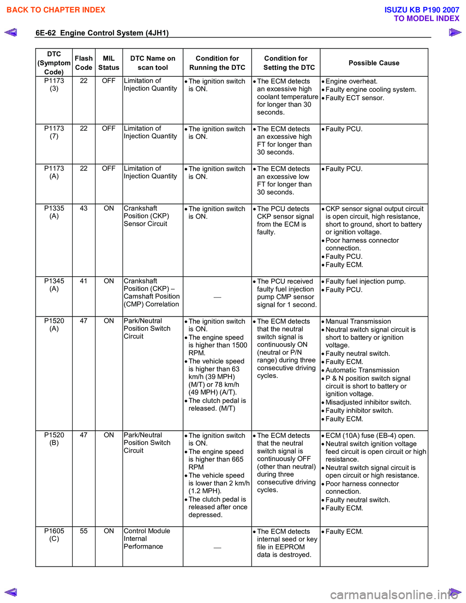
6E-62 Engine Control System (4JH1)
DTC
(Symptom Code) Flash
Code MIL
Status DTC Name on
scan tool Condition for
Running the DTC Condition for
Setting the DTC Possible Cause
P1173
(3) 22 OFF Limitation of
Injection Quantity •
The ignition switch
is ON. •
The ECM detects
an excessive high
coolant temperature
for longer than 30
seconds.
•
Engine overheat.
• Faulty engine cooling system.
• Faulty ECT sensor.
P1173 (7) 22 OFF Limitation of
Injection Quantity
•
The ignition switch
is ON. •
The ECM detects
an excessive high
FT for longer than
30 seconds.
•
Faulty PCU.
P1173 (A) 22 OFF Limitation of
Injection Quantity
•
The ignition switch
is ON. •
The ECM detects
an excessive low
FT for longer than
30 seconds.
•
Faulty PCU.
P1335 (A) 43 ON Crankshaft
Position (CKP)
Sensor Circuit •
The ignition switch
is ON. •
The PCU detects
CKP sensor signal
from the ECM is
faulty.
•
CKP sensor signal output circuit
is open circuit, high resistance,
short to ground, short to battery
or ignition voltage.
• Poor harness connector
connection.
• Faulty PCU.
• Faulty ECM.
P1345 (A) 41 ON Crankshaft
Position (CKP) –
Camshaft Position
(CMP) Correlation
•
The PCU received
faulty fuel injection
pump CMP sensor
signal for 1 second.
•
Faulty fuel injection pump.
• Faulty PCU.
P1520 (A) 47 ON Park/Neutral
Position Switch
Circuit •
The ignition switch
is ON.
• The engine speed
is higher than 1500
RPM.
• The vehicle speed
is higher than 63
km/h (39 MPH)
(M/T) or 78 km/h
(49 MPH) (A/T).
• The clutch pedal is
released. (M/T)
•
The ECM detects
that the neutral
switch signal is
continuously ON
(neutral or P/N
range) during three
consecutive driving
cycles.
•
Manual Transmission
• Neutral switch signal circuit is
short to battery or ignition
voltage.
• Faulty neutral switch.
• Faulty ECM.
• Automatic Transmission
• P & N position switch signal
circuit is short to battery or
ignition voltage.
• Misadjusted inhibitor switch.
• Faulty inhibitor switch.
• Faulty ECM.
P1520 (B) 47 ON Park/Neutral
Position Switch
Circuit •
The ignition switch
is ON.
• The engine speed
is higher than 665
RPM
• The vehicle speed
is lower than 2 km/h
(1.2 MPH).
• The clutch pedal is
released after once
depressed.
•
The ECM detects
that the neutral
switch signal is
continuously OFF
(other than neutral)
during three
consecutive driving
cycles.
•
ECM (10A) fuse (EB-4) open.
• Neutral switch ignition voltage
feed circuit is open circuit or high
resistance.
• Neutral switch signal circuit is
open circuit or high resistance.
• Poor harness connector
connection.
• Faulty neutral switch.
• Faulty ECM.
P1605 (C) 55 ON Control Module
Internal
Performance •
The ECM detects
internal seed or key
file in EEPROM
data is destroyed.
•
Faulty ECM.
BACK TO CHAPTER INDEX
TO MODEL INDEX
ISUZU KB P190 2007
Page 1097 of 6020
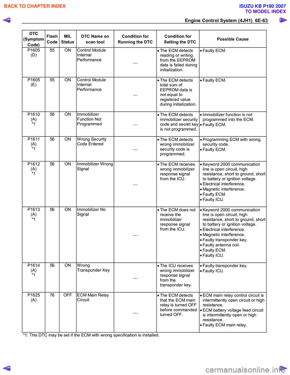
Engine Control System (4JH1) 6E-63
DTC
(Symptom Code) Flash
Code MIL
Status DTC Name on
scan tool Condition for
Running the DTC Condition for
Setting the DTC Possible Cause
P1605
(D) 55 ON Control Module
Internal
Performance •
The ECM detects
reading or writing
from the EEPROM
data is failed during
initialization.
•
Faulty ECM.
P1605
(E) 55 ON Control Module
Internal
Performance
•
The ECM detects
total sum of
EEPROM data is
not equal to
registered value
during initialization.
•
Faulty ECM.
P1610
(A) *1 56 ON Immobilizer
Function Not
Programmed •
The ECM detects
immobilizer security
code and secret key
is not programmed.
•
Immobilizer function is not
programmed into the ECM.
• Faulty ECM.
P1611 (A) *1 56 ON W rong Security
Code Entered
•
The ECM detects
wrong immobilizer
security code is
programmed.
•
Programming ECM with wrong
security code.
• Faulty ECM.
P1612 (A) *1 56 ON Immobilizer W rong
Signal
•
The ECM receives
wrong immobilizer
response signal
from the ICU.
•
Keyword 2000 communication
line is open circuit, high
resistance, short to ground, short
to battery or ignition voltage.
• Electrical interference.
• Magnetic interference.
• Faulty ECM.
• Faulty ICU.
P1613 (A) *1 56 ON Immobilizer No
Signal
•
The ECM does not
receive the
immobilizer
response signal
from the ICU.
•
Keyword 2000 communication
line is open circuit, high
resistance, short to ground, short
to battery or ignition voltage.
• Electrical interference.
• Magnetic interference.
• Faulty transponder key.
• Faulty antenna coil.
• Faulty ECM.
• Faulty ICU.
P1614 (A) *1 56 ON W rong
Transponder Key
•
The ICU receives
wrong immobilizer
response signal
from the
transponder key.
•
Faulty transponder key.
• Faulty ICU.
P1625 (A) 76 OFF ECM Main Relay
Circuit
•
The ECM detects
that the ECM main
relay is turned OFF
before commanded
turned OFF.
•
ECM main relay control circuit is
intermittently open circuit or high
resistance.
• ECM battery voltage feed circuit
is intermittently open or high
resistance.
• Faulty ECM main relay.
*1: This DTC may be set if the ECM with wrong specification is installed.
BACK TO CHAPTER INDEX
TO MODEL INDEX
ISUZU KB P190 2007
Page 1109 of 6020
Engine Control System (4JH1) 6E-75
DTC P0105 (Symptom Code 1) (Flash Code 34)
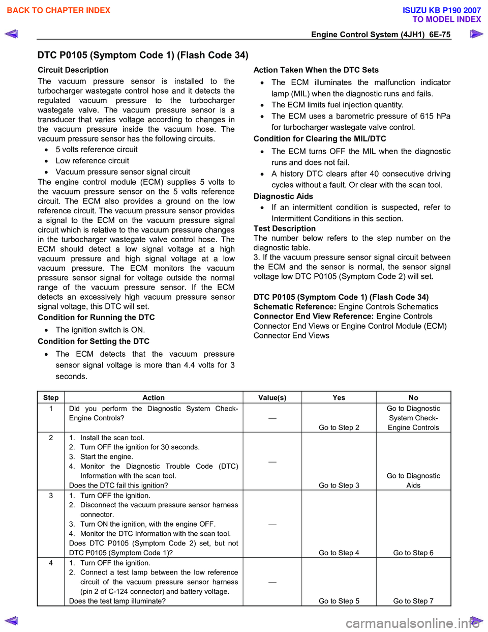
Circuit Description
The vacuum pressure sensor is installed to the
turbocharger wastegate control hose and it detects the
regulated vacuum pressure to the turbocharge
r
wastegate valve. The vacuum pressure sensor is a
transducer that varies voltage according to changes in
the vacuum pressure inside the vacuum hose. The
vacuum pressure sensor has the following circuits.
• 5 volts reference circuit
• Low reference circuit
• Vacuum pressure sensor signal circuit
The engine control module (ECM) supplies 5 volts to
the vacuum pressure sensor on the 5 volts reference
circuit. The ECM also provides a ground on the lo
w
reference circuit. The vacuum pressure sensor provides
a signal to the ECM on the vacuum pressure signal
circuit which is relative to the vacuum pressure changes
in the turbocharger wastegate valve control hose. The
ECM should detect a low signal voltage at a high
vacuum pressure and high signal voltage at a lo
w
vacuum pressure. The ECM monitors the vacuum
pressure sensor signal for voltage outside the normal
range of the vacuum pressure sensor. If the ECM
detects an excessively high vacuum pressure senso
r
signal voltage, this DTC will set.
Condition for Running the DTC
• The ignition switch is ON.
Condition for Setting the DTC
• The ECM detects that the vacuum pressure
sensor signal voltage is more than 4.4 volts for 3
seconds.
Action Taken When the DTC Sets
• The ECM illuminates the malfunction indicato
r
lamp (MIL) when the diagnostic runs and fails.
• The ECM limits fuel injection quantity.
• The ECM uses a barometric pressure of 615 hPa
for turbocharger wastegate valve control.
Condition for Clearing the MIL/DTC
• The ECM turns OFF the MIL when the diagnostic
runs and does not fail.
• A history DTC clears after 40 consecutive driving
cycles without a fault. Or clear with the scan tool.
Diagnostic Aids
• If an intermittent condition is suspected, refer to
Intermittent Conditions in this section.
Test Description
The number below refers to the step number on the
diagnostic table.
3. If the vacuum pressure sensor signal circuit between
the ECM and the sensor is normal, the sensor signal
voltage low DTC P0105 (Symptom Code 2) will set.
DTC P0105 (Symptom Code 1) (Flash Code 34)
Schematic Reference: Engine Controls Schematics
Connector End View Reference: Engine Controls
Connector End Views or Engine Control Module (ECM)
Connector End Views
Step Action Value(s) Yes No
1 Did you perform the Diagnostic System Check-
Engine Controls?
Go to Step 2 Go to Diagnostic
System Check-
Engine Controls
2 1. Install the scan tool. 2. Turn OFF the ignition for 30 seconds.
3. Start the engine.
4. Monitor the Diagnostic Trouble Code (DTC) Information with the scan tool.
Does the DTC fail this ignition?
Go to Step 3 Go to Diagnostic
Aids
3 1. Turn OFF the ignition. 2. Disconnect the vacuum pressure sensor harness connector.
3. Turn ON the ignition, with the engine OFF.
4. Monitor the DTC Information with the scan tool.
Does DTC P0105 (Symptom Code 2) set, but not
DTC P0105 (Symptom Code 1)?
Go to Step 4 Go to Step 6
4 1. Turn OFF the ignition. 2. Connect a test lamp between the low reference circuit of the vacuum pressure sensor harness
(pin 2 of C-124 connector) and battery voltage.
Does the test lamp illuminate?
Go to Step 5 Go to Step 7
BACK TO CHAPTER INDEX
TO MODEL INDEX
ISUZU KB P190 2007
Page 1112 of 6020
6E-78 Engine Control System (4JH1)
DTC P0105 (Symptom Code 2) (Flash Code 34)
Circuit Description
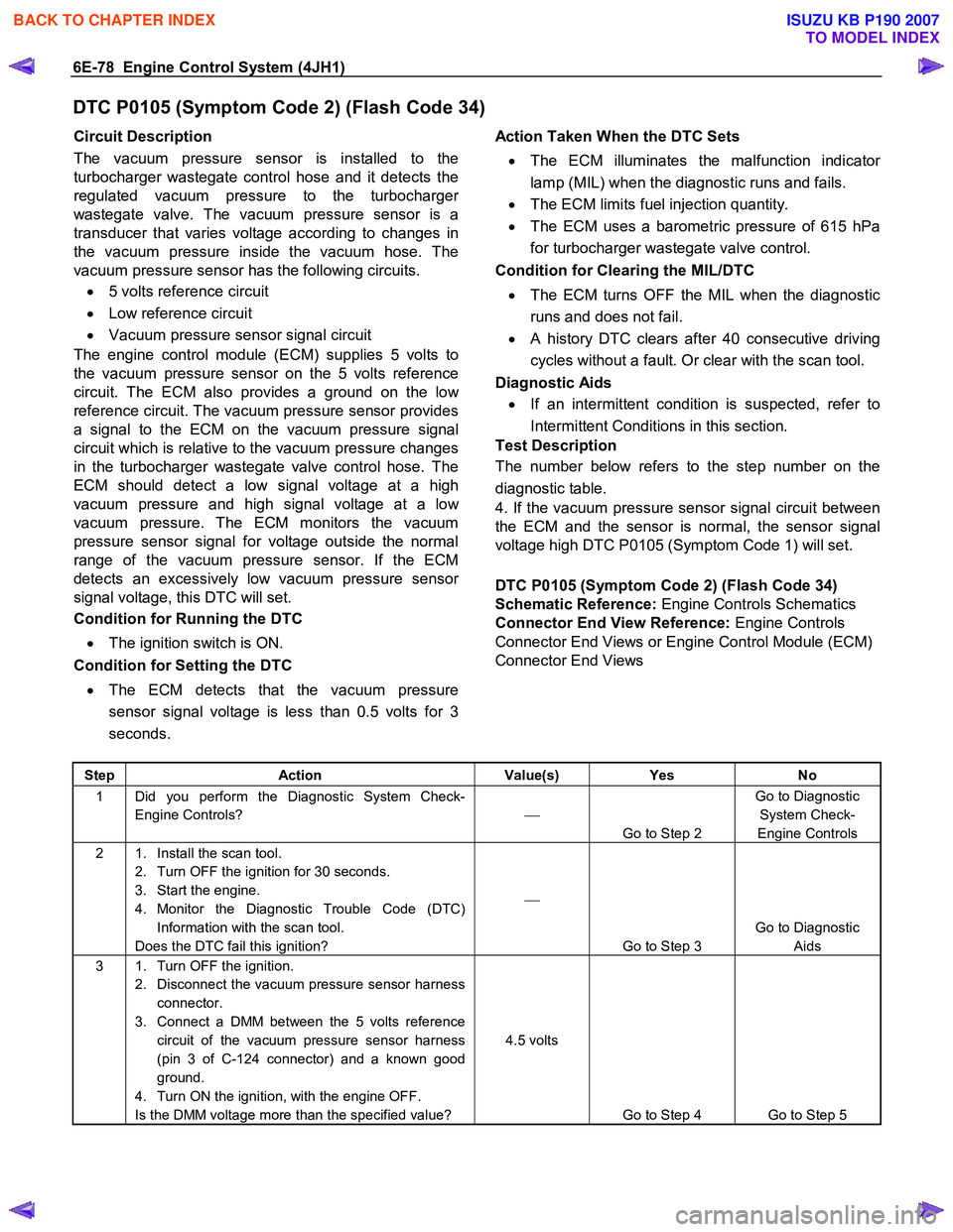
The vacuum pressure sensor is installed to the
turbocharger wastegate control hose and it detects the
regulated vacuum pressure to the turbocharge
r
wastegate valve. The vacuum pressure sensor is a
transducer that varies voltage according to changes in
the vacuum pressure inside the vacuum hose. The
vacuum pressure sensor has the following circuits.
• 5 volts reference circuit
• Low reference circuit
• Vacuum pressure sensor signal circuit
The engine control module (ECM) supplies 5 volts to
the vacuum pressure sensor on the 5 volts reference
circuit. The ECM also provides a ground on the lo
w
reference circuit. The vacuum pressure sensor provides
a signal to the ECM on the vacuum pressure signal
circuit which is relative to the vacuum pressure changes
in the turbocharger wastegate valve control hose. The
ECM should detect a low signal voltage at a high
vacuum pressure and high signal voltage at a lo
w
vacuum pressure. The ECM monitors the vacuum
pressure sensor signal for voltage outside the normal
range of the vacuum pressure sensor. If the ECM
detects an excessively low vacuum pressure senso
r
signal voltage, this DTC will set.
Condition for Running the DTC
• The ignition switch is ON.
Condition for Setting the DTC
• The ECM detects that the vacuum pressure
sensor signal voltage is less than 0.5 volts for 3
seconds.
Action Taken When the DTC Sets
• The ECM illuminates the malfunction indicato
r
lamp (MIL) when the diagnostic runs and fails.
• The ECM limits fuel injection quantity.
• The ECM uses a barometric pressure of 615 hPa
for turbocharger wastegate valve control.
Condition for Clearing the MIL/DTC
• The ECM turns OFF the MIL when the diagnostic
runs and does not fail.
• A history DTC clears after 40 consecutive driving
cycles without a fault. Or clear with the scan tool.
Diagnostic Aids
• If an intermittent condition is suspected, refer to
Intermittent Conditions in this section.
Test Description
The number below refers to the step number on the
diagnostic table.
4. If the vacuum pressure sensor signal circuit between
the ECM and the sensor is normal, the sensor signal
voltage high DTC P0105 (Symptom Code 1) will set.
DTC P0105 (Symptom Code 2) (Flash Code 34)
Schematic Reference: Engine Controls Schematics
Connector End View Reference: Engine Controls
Connector End Views or Engine Control Module (ECM)
Connector End Views
Step Action Value(s) Yes No
1 Did you perform the Diagnostic System Check-
Engine Controls?
Go to Step 2 Go to Diagnostic
System Check-
Engine Controls
2 1. Install the scan tool. 2. Turn OFF the ignition for 30 seconds.
3. Start the engine.
4. Monitor the Diagnostic Trouble Code (DTC) Information with the scan tool.
Does the DTC fail this ignition?
Go to Step 3 Go to Diagnostic
Aids
3 1. Turn OFF the ignition. 2. Disconnect the vacuum pressure sensor harness connector.
3. Connect a DMM between the 5 volts reference circuit of the vacuum pressure sensor harness
(pin 3 of C-124 connector) and a known good
ground.
4. Turn ON the ignition, with the engine OFF.
Is the DMM voltage more than the specified value? 4.5 volts
Go to Step 4 Go to Step 5
BACK TO CHAPTER INDEX
TO MODEL INDEX
ISUZU KB P190 2007
Page 1115 of 6020
Engine Control System (4JH1) 6E-81
DTC P0105 (Symptom Code 7) (Flash Code 34)
Circuit Description
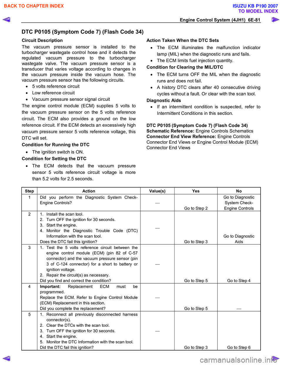
The vacuum pressure sensor is installed to the
turbocharger wastegate control hose and it detects the
regulated vacuum pressure to the turbocharge
r
wastegate valve. The vacuum pressure sensor is a
transducer that varies voltage according to changes in
the vacuum pressure inside the vacuum hose. The
vacuum pressure sensor has the following circuits.
• 5 volts reference circuit
• Low reference circuit
• Vacuum pressure sensor signal circuit
The engine control module (ECM) supplies 5 volts to
the vacuum pressure sensor on the 5 volts reference
circuit. The ECM also provides a ground on the lo
w
reference circuit. If the ECM detects an excessively high
vacuum pressure sensor 5 volts reference voltage, this
DTC will set.
Condition for Running the DTC
• The ignition switch is ON.
Condition for Setting the DTC
• The ECM detects that the vacuum pressure
sensor 5 volts reference circuit voltage is more
than 5.2 volts for 2.5 seconds.
Action Taken When the DTC Sets
• The ECM illuminates the malfunction indicato
r
lamp (MIL) when the diagnostic runs and fails.
• The ECM limits fuel injection quantity.
Condition for Clearing the MIL/DTC
• The ECM turns OFF the MIL when the diagnostic
runs and does not fail.
• A history DTC clears after 40 consecutive driving
cycles without a fault. Or clear with the scan tool.
Diagnostic Aids
• If an intermittent condition is suspected, refer to
Intermittent Conditions in this section.
DTC P0105 (Symptom Code 7) (Flash Code 34)
Schematic Reference: Engine Controls Schematics
Connector End View Reference: Engine Controls
Connector End Views or Engine Control Module (ECM)
Connector End Views
Step Action Value(s) Yes No
1 Did you perform the Diagnostic System Check-
Engine Controls?
Go to Step 2 Go to Diagnostic
System Check-
Engine Controls
2 1. Install the scan tool. 2. Turn OFF the ignition for 30 seconds.
3. Start the engine.
4. Monitor the Diagnostic Trouble Code (DTC) Information with the scan tool.
Does the DTC fail this ignition?
Go to Step 3 Go to Diagnostic
Aids
3 1. Test the 5 volts reference circuit between the engine control module (ECM) (pin 82 of C-57
connector) and the vacuum pressure sensor (pin
3 of C-124 connector) for a short to battery or
ignition voltage.
2. Repair the circuit(s) as necessary.
Did you find and correct the condition?
Go to Step 5 Go to Step 4
4 Important: Replacement ECM must be
programmed.
Replace the ECM. Refer to Engine Control Module
(ECM) Replacement in this section.
Did you complete the replacement?
Go to Step 5
5 1. Reconnect all previously disconnected harness
connector(s).
2. Clear the DTCs with the scan tool.
3. Turn OFF the ignition for 30 seconds.
4. Start the engine.
5. Monitor the DTC Information with the scan tool.
Did the DTC fail this ignition?
Go to Step 3 Go to Step 6
BACK TO CHAPTER INDEX
TO MODEL INDEX
ISUZU KB P190 2007
Page 1117 of 6020
Engine Control System (4JH1) 6E-83
DTC P0105 (Symptom Code 9) (Flash Code 34)
Circuit Description
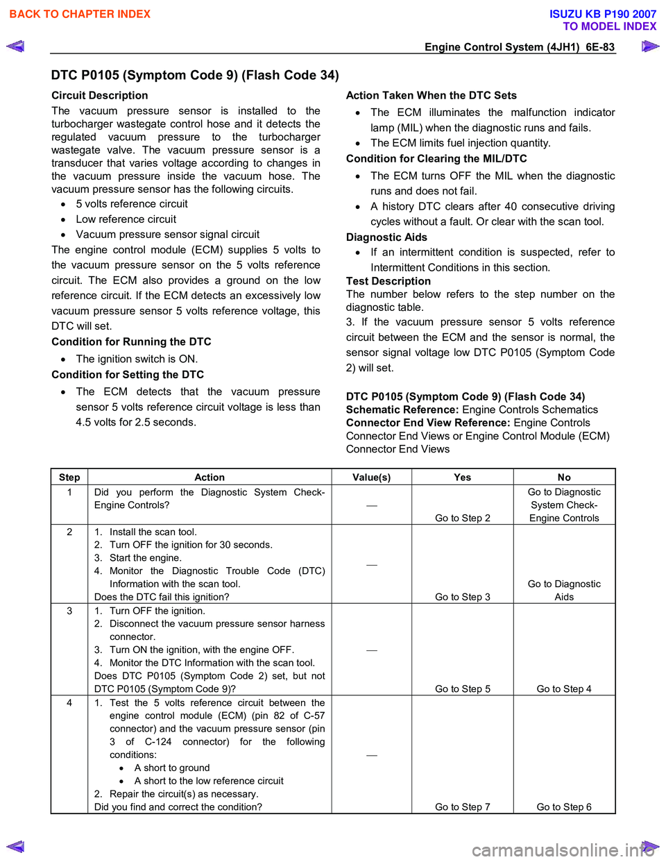
The vacuum pressure sensor is installed to the
turbocharger wastegate control hose and it detects the
regulated vacuum pressure to the turbocharge
r
wastegate valve. The vacuum pressure sensor is a
transducer that varies voltage according to changes in
the vacuum pressure inside the vacuum hose. The
vacuum pressure sensor has the following circuits.
• 5 volts reference circuit
• Low reference circuit
• Vacuum pressure sensor signal circuit
The engine control module (ECM) supplies 5 volts to
the vacuum pressure sensor on the 5 volts reference
circuit. The ECM also provides a ground on the lo
w
reference circuit. If the ECM detects an excessively low
vacuum pressure sensor 5 volts reference voltage, this
DTC will set.
Condition for Running the DTC
• The ignition switch is ON.
Condition for Setting the DTC
• The ECM detects that the vacuum pressure
sensor 5 volts reference circuit voltage is less than
4.5 volts for 2.5 seconds.
Action Taken When the DTC Sets
• The ECM illuminates the malfunction indicato
r
lamp (MIL) when the diagnostic runs and fails.
• The ECM limits fuel injection quantity.
Condition for Clearing the MIL/DTC
• The ECM turns OFF the MIL when the diagnostic
runs and does not fail.
• A history DTC clears after 40 consecutive driving
cycles without a fault. Or clear with the scan tool.
Diagnostic Aids
• If an intermittent condition is suspected, refer to
Intermittent Conditions in this section.
Test Description
The number below refers to the step number on the
diagnostic table.
3. If the vacuum pressure sensor 5 volts reference
circuit between the ECM and the sensor is normal, the
sensor signal voltage low DTC P0105 (Symptom Code
2) will set.
DTC P0105 (Symptom Code 9) (Flash Code 34)
Schematic Reference: Engine Controls Schematics
Connector End View Reference: Engine Controls
Connector End Views or Engine Control Module (ECM)
Connector End Views
Step Action Value(s) Yes No
1 Did you perform the Diagnostic System Check-
Engine Controls?
Go to Step 2 Go to Diagnostic
System Check-
Engine Controls
2 1. Install the scan tool. 2. Turn OFF the ignition for 30 seconds.
3. Start the engine.
4. Monitor the Diagnostic Trouble Code (DTC) Information with the scan tool.
Does the DTC fail this ignition?
Go to Step 3 Go to Diagnostic
Aids
3 1. Turn OFF the ignition. 2. Disconnect the vacuum pressure sensor harness connector.
3. Turn ON the ignition, with the engine OFF.
4. Monitor the DTC Information with the scan tool.
Does DTC P0105 (Symptom Code 2) set, but not
DTC P0105 (Symptom Code 9)?
Go to Step 5 Go to Step 4
4 1. Test the 5 volts reference circuit between the engine control module (ECM) (pin 82 of C-57
connector) and the vacuum pressure sensor (pin
3 of C-124 connector) for the following
conditions: • A short to ground
• A short to the low reference circuit
2. Repair the circuit(s) as necessary.
Did you find and correct the condition?
Go to Step 7 Go to Step 6
BACK TO CHAPTER INDEX
TO MODEL INDEX
ISUZU KB P190 2007