2007 ISUZU KB P190 trans
[x] Cancel search: transPage 726 of 6020
BRAKES 5C-27
15. Repeat steps 12 through 14 until no air comes out of the
port when the brake pipe is loosened
NOTE: Be very careful not to allow the brake fluid to come in contact with painted surfaces.
RTW 75CSH001801
16. Bleed the air from the front wheel brake pipe connection (2)
by repeating steps 6 through 15.
Bleeding the Caliper
17. Bleed the air from each wheel in the order listed below: • Right rear wheel cylinder
• Left rear wheel cylinder
• Left front caliper
• Right front caliper
Conduct air bleeding from the wheels in the above order. I
f
no brake fluid comes out, it suggests that air is mixed in the
master cylinder. In this case, bleed air from the maste
r
cylinder in accordance with steps 6 through 16, and then
bleed air from the caliper or wheel cylinder.
RTW 35CSH000501
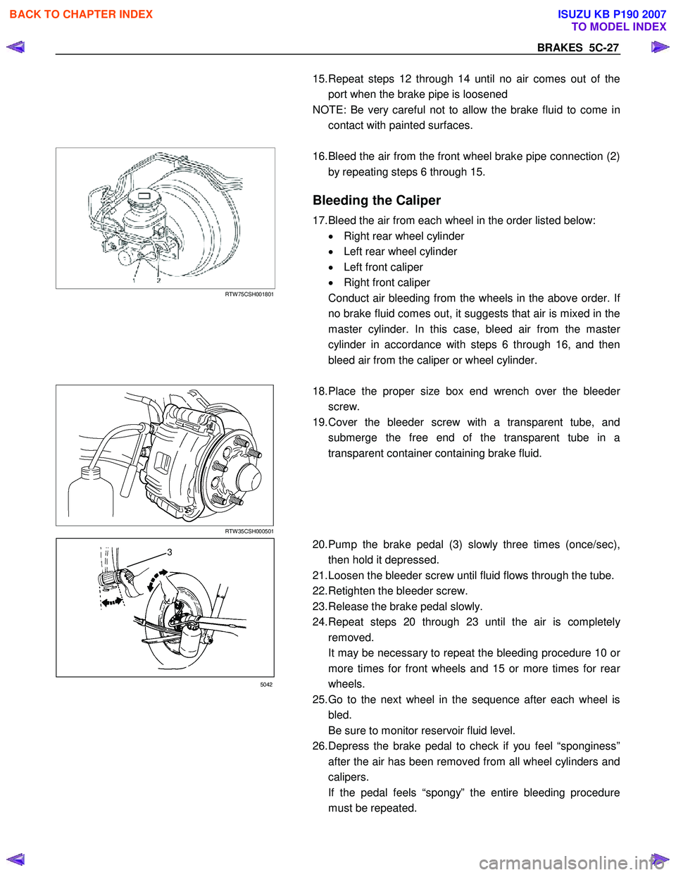
18. Place the proper size box end wrench over the bleeder
screw.
19. Cover the bleeder screw with a transparent tube, and submerge the free end of the transparent tube in a
transparent container containing brake fluid.
3
5042
20. Pump the brake pedal (3) slowly three times (once/sec),
then hold it depressed.
21. Loosen the bleeder screw until fluid flows through the tube.
22. Retighten the bleeder screw.
23. Release the brake pedal slowly.
24. Repeat steps 20 through 23 until the air is completel
y
removed.
It may be necessary to repeat the bleeding procedure 10 o
r
more times for front wheels and 15 or more times for rear
wheels.
25. Go to the next wheel in the sequence after each wheel is bled.
Be sure to monitor reservoir fluid level.
26. Depress the brake pedal to check if you feel “sponginess” after the air has been removed from all wheel cylinders and
calipers.
If the pedal feels “spongy” the entire bleeding procedure must be repeated.
BACK TO CHAPTER INDEX
TO MODEL INDEX
ISUZU KB P190 2007
Page 771 of 6020

PARKING BRAKE SYSTEM 5D-1
Service Precaution
Service Precaution
WARNING: THIS VEHICLE HAS A SUPPLEMENTAL
RESTRAINT SYSTEM (SRS). REFER TO THE SRS
COMPONENT AND WIRING LOCATION VIEW IN
ORDER TO DETERMINE WHETHER YOU ARE
PERFORMING SERVICE ON OR NEAR THE SRS
COMPONENTS OR THE SRS WIRING. WHEN YOU
ARE PERFORMING SERVICE ON OR NEAR THE
SRS COMPONENTS OR THE SRS WIRING, REFER
TO THE SRS SERVICE INFORMATION. FAILURE TO
FOLLOW WARNINGS COULD RESULT IN
POSSIBLE AIR BAG DEPLOYMENT, PERSONAL
INJURY, OR OTHERWISE UNNECESSARY SRS
SYSTEM REPAIRS.
CAUTION: Always use the correct fastener in the
proper location. When you replace a fastener, use
ONLY the exact part number for that application.
ISUZU/GM will call out those fasteners that require
a replacement after removal. ISUZU/GM will also
call out the fasteners that require thread lockers o
r
thread sealant. UNLESS OTHERWISE SPECIFIED,
do not use supplemental coatings (paints, greases,
or other corrosion inhibitors) on threaded fasteners
or fastener joint interfaces. Generally, such
coatings adversely affect the fastener torque and
the joint clamping force, and may damage the
fastener. When you install fasteners, use the
correct tightening sequence and specifications.
Following these instructions can help you avoid
damage to parts and systems.
General Description
Pulling up the parking brake lever by hand will set the
parking brake. By means of a ratchet type lock, the
lever can be held in that position until it is released. The
position of the lever is transmitted through cable/leve
r
systems to the rear wheels. These parts are designed
to obtain sufficient braking force even when parking on
slopes. W hen the parking brake is set, or when the
ignition SW is in the “ON” position, the brake warning
light illuminates. The rear wheel parking brake is a
leading-trailing brake (mechanical inside expansion
type) built in the rear drum brake. Parking brake
adjustment is made through the adjusting hole (bored
through back plate). Parking brake lever stroke should
be adjusted to 8 −14 notches with 294N (30 kg / 66 lb)
(bench seat) or 6 −9 notches with 294N (30 kg / 66 lb)
(bucket seat). Refer to “Parking Brake Adjustment” in
this section.
BACK TO CHAPTER INDEX
TO MODEL INDEX
ISUZU KB P190 2007
Page 775 of 6020

PARKING BRAKE SYSTEM 5D-5
Front Parking Brake Cable
Front Parking Brake Cable and Associated Parts (Bench Seat)
RTW 75DMF000301
Legend
(1) Shift Knob (manual transmission)
(2) Front Floor Console
(3) Bolt
(4) Seat Assembly
(5) Buckle: side seat and Center Seat Belt
(6) Seat Adjuster
BACK TO CHAPTER INDEX
TO MODEL INDEX
ISUZU KB P190 2007
Page 827 of 6020

6A – 22 ENGINE MECHANICAL
RECOMMENDED LIQUID GASKET
Type Brand Name Manufacturer Remarks
RTV*
Silicon Base ThreeBond 1207B
ThreeBond 1207C Three Bond
Three Bond
W ater Base
ThreeBond 1141E
ThreeBond 1215 Three Bond
Three Bond
Solvent
ThreeBond 1104
Belco Bond 4
Belco Bond 401
Belco Bond 402 Three Bond
Isuzu
Isuzu
Isuzu
Anaerobic
LOCTITE 515
LOCTITE 518
LOCTITE 262 Loctite
Loctite
Loctite Recommended for
transaxle repairs
* RTV : Room Temperature Vulcanizer
Note:
1. It is very important that the liquid gaskets listed above or their exact equivalent be used on the vehicle.
2. Be careful to use the specified amount of liquid gasket. Follow the manufacturer’s instructions at all times.
3. Be absolutely sure to remove all lubricants and moisture from the connecting surfaces before applying the liquid gasket.
The connecting surfaces must be perfectly dry.
4. LOCTITE 515 and LOCTITE 518 harden upon contact with a metal surface. Do not apply LOCTITE 515 or LOCTITE 518 between two metal surfaces having a clearance of
greater than 0.25 mm (0.01 in). Poor adhesion will result.
BACK TO CHAPTER INDEX
TO MODEL INDEX
ISUZU KB P190 2007
Page 839 of 6020

6A – 34 ENGINE MECHANICAL
RTW 46ASH000701
9. Turn the crankshaft clockwise and read the gauge
indication when the crankshaft pulley timing mark (8 °)
is aligned with the pointer.
Injection Timing : BTDC 8 ° ± 2 °
Standard Reading mm (in)
0.5 (0.02)
If the injection timing is outside the specified range,
continue with the following steps.
10. Loosen the injection pump fixing nuts and bracket bolts.
11. Adjust the injection pump setting angle.
W hen large than standard value W hen smaller than standard
value
R A
A: Move the injection pump toward the engine.
R: Move the injection pump away from the engine.
12. Install the distributor head bolt.
Distributor head bolt torque N·m (kg·m /lb·ft)
29 (3.0/22)
ENGINE CONTROL (4JA1T(L) only)
Idling Speed Adjustment
1. Set the vehicle parking brake and chock the drive wheels.
2. Place the transmission in neutral.
3. Start the engine and allow it to idle until the coolant temperature reaches 70 - 80 °C (158 - 176 °F).
4. Disconnect the engine control cable from the control lever.
5. Set a tachometer to the engine.
6. Check the engine idling speed. If the engine idling speed is outside the specified
range, it must be adjusted.
Engine Idling Speed : 730 ± 25 rpm
BACK TO CHAPTER INDEX
TO MODEL INDEX
ISUZU KB P190 2007
Page 842 of 6020

ENGINE MECHANICAL 6A – 37
REMOVAL AND INSTALLATION
Read this section carefully before performing any removal and installation procedure. This section gives
you important points as well as the order of operation. Be sure that you understand everything in this section before
you begin.
Removal
P1010011
1. Battery
1) Disconnect the battery cable and the grounding cable from the battery terminals.
2) Remove the battery clamp. Take care not to accidentally short the battery with the wrench or some
other tool.
3) Remove the battery.
4) Disconnect the battery cable at the starter motor and the ground cable at the cylinder body.
2. Engine Hood Apply setting marks to the engine hood and the engine
hood hinges before removing the engine hood. This will
facilitate reinstallation of the engine hood to its original
position.
3. Supporting the Vehicle 1) Jack up the vehicle.
2) Place chassis stands at the front and the rear of the vehicle.
4. Under cover (for 4x4 model) 5. Rear propeller shaft 1) Remove the propeller shaft flange yoke at the rear differential.
2) Remove the center bearing retainer bolts.
3) Remove the propeller shaft together with the center bearing from the transmission mainshaft spline.
F06R300006 P1010002
BACK TO CHAPTER INDEX
TO MODEL INDEX
ISUZU KB P190 2007
Page 843 of 6020

6A – 38 ENGINE MECHANICAL
6. Front propeller shaft (for 4x4 model)
Remove the spline yoke flange bolt at the transfer output
shaft.
Do not allow the spline yoke to fall away from the front
propeller shaft.
If the spline yoke should fall away from the front propeller
shaft, align the setting marks on the spline yoke and the
propeller shaft to reassemble the two marks. The setting
marks are punched circles approx. 3mm (0.12 in) in
diameter.
7. Clutch slave cylinder (for M/T model)
8. ATF pipe (for A/T model)
9 Shift control cable (for A/T model)
10. Transmission sensor harness Remove the vehicle speed sensor connector, inhibitor
switch connector (A/T), ATF temperature sensor
connector, back up light switch connector (M/T) from
transmission.
11. Breather hose (for A/T model)
12. Transmission shift lever (for M/T model) Remove the shift lever from the floor.
13. Transfer shift lever (for 4x4 model) Remove the shift lever from the floor.
14. Transmission member 1) Support the transmission with the transmission jack.
2) Remove the transmission member mounting bolts fixing the transmission member to the chassis frame.
15. Torque converter bolt (for A/T model) 1) Remove the under cover under the torque converter housing.
2) Rotate the flywheel by using tire lever or some other tool, and then remove the torque converter bolts.
16. Transmission coupling bolt 1) Support the engine with the garage jack.
2) Use the jack to slightly lower the transmission.
3) Remove the transmission coupling bolts.
17. Transmission (and transfer) Separate the transmission (and transfer) from the
engine.Take care not to damage the transmission, the
engine, and their related parts..
F06R300007
P1010025
BACK TO CHAPTER INDEX
TO MODEL INDEX
ISUZU KB P190 2007
Page 846 of 6020

ENGINE MECHANICAL 6A – 41
Coolant Replenishment
Warning:
When the coolant is heated to a high temperature, be
sure not to loosen or remove the rediator cap.
Otherwise you might get scalded by hot vapor or
boiling water.
To open the radiator cap, put a piece of thick cloth on
the cap and loosen the cap slowly to reduce the
pressure when the coolant has become cooler.
1. Open rediator cap pour coolant up to filler neck
2. Pour coolant into reservoir tank up to "MAX" line
3. Tighten radiator cap and start the engine. After idling for 2 to 3 minutes, stop the engine and reopen radiator
cap. If the water level is lower, replenish.
4. After replenish the coolant tighten radiator cap, warm up the engine at about 2000 rpm. Set heater
adjustment to the highest temperature position, and let
the coolant circulate also into heater water system.
5. Check to see the thermometer, continuously idling 5 minutes and stop the engine.
6. W hen the engine has been cooled, check filler neck for water level and replenish if required. Should extreme
shortage of coolant is found, check the coolant system
and reservoir tank hose for leakage.
7. Pour coolant into the reservoir tank up to "MAX" line.
Coolant Capacity lit (US/UK gal)
4JA1 / TC 9.4 (2.5 / 2.1)
4JH1TC M/T: 10.1 (2.7 / 2.2)
A/T: 10.0 (2.6 / 2.2)
Engine Warm-Up
After completing the required maintenance procedures,
start the engine and allow it to idle until it is warm.
Check the following:
1. Engine idling speed.
2. Engine noise level.
3. Engine lubricating system and cooling system. Carefully check for oil and coolant leakage.
4. Clutch engagement.
5. Transmission operation.
6. Indicator warning light operation.
BACK TO CHAPTER INDEX
TO MODEL INDEX
ISUZU KB P190 2007