2007 ISUZU KB P190 check transmission fluid
[x] Cancel search: check transmission fluidPage 3955 of 6020
Automatic Transmission – 4L60E – On-vehicle Servicing Page 7C4–42
5 Carefully lower the rear of the transmission sufficiently to get access to the cooler lines.
6 Place a suitable sized drip tray underneath the transmission.
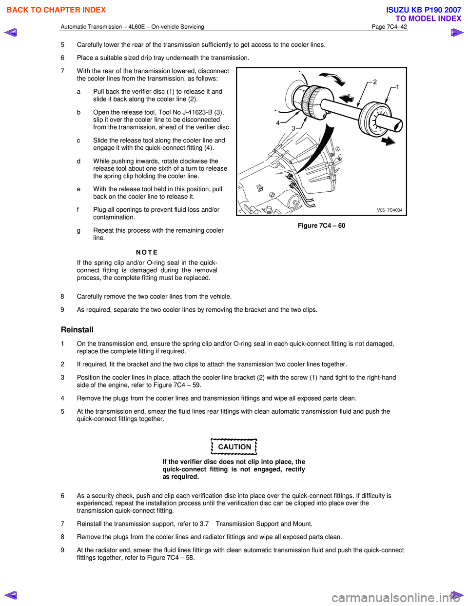
7 W ith the rear of the transmission lowered, disconnect the cooler lines from the transmission, as follows:
a Pull back the verifier disc (1) to release it and slide it back along the cooler line (2).
b Open the release tool, Tool No J-41623-B (3), slip it over the cooler line to be disconnected
from the transmission, ahead of the verifier disc.
c Slide the release tool along the cooler line and engage it with the quick-connect fitting (4).
d W hile pushing inwards, rotate clockwise the release tool about one sixth of a turn to release
the spring clip holding the cooler line.
e With the release tool held in this position, pull back on the cooler line to release it.
f Plug all openings to prevent fluid loss and/or contamination.
g Repeat this process with the remaining cooler line.
NOTE
If the spring clip and/or O-ring seal in the quick-
connect fitting is damaged during the removal
process, the complete fitting must be replaced.
Figure 7C4 – 60
8 Carefully remove the two cooler lines from the vehicle.
9 As required, separate the two cooler lines by removing the bracket and the two clips.
Reinstall
1 On the transmission end, ensure the spring clip and/or O-ring seal in each quick-connect fitting is not damaged, replace the complete fitting if required.
2 If required, fit the bracket and the two clips to attach the transmission two cooler lines together.
3 Position the cooler lines in place, attach the cooler line bracket (2) with the screw (1) hand tight to the right-hand side of the engine, refer to Figure 7C4 – 59.
4 Remove the plugs from the cooler lines and transmission fittings and wipe all exposed parts clean.
5 At the transmission end, smear the fluid lines rear fittings with clean automatic transmission fluid and push the quick-connect fittings together.
If the verifier disc does not clip into place, the
quick-connect fitting is not engaged, rectify
as required.
6 As a security check, push and clip each verification disc into place over the quick-connect fittings. If difficulty is experienced, repeat the installation process until the verification disc can be clipped into place over the
transmission quick-connect fitting.
7 Reinstall the transmission support, refer to 3.7 Transmission Support and Mount.
8 Remove the plugs from the cooler lines and radiator fittings and wipe all exposed parts clean.
9 At the radiator end, smear the fluid lines fittings with clean automatic transmission fluid and push the quick-connect fittings together, refer to Figure 7C4 – 58.
BACK TO CHAPTER INDEX
TO MODEL INDEX
ISUZU KB P190 2007
Page 3956 of 6020
Automatic Transmission – 4L60E – On-vehicle Servicing Page 7C4–43
If the verifier disc does not clip into place, the
quick-connect fitting is not engaged, rectify
as required.
10 As a security check, push and clip each verification disc into place over the quick-connect fittings. If difficulty is experienced, repeat the installation process until the verification disc can be clipped into place over the radiator
quick-connect fitting.
11 Snap the outlet cooler line (4) in the clip (5) of the radiator fan shroud.
12 Ensure the routeing of the cooler lines is correct and there is no fouling of the lines.
13 Tighten the screw attaching the cooler lines bracket to the correct torque specifications.
Transmission cooler lines bracket
attaching screw torque specification .................. 23.0 Nm
14 If required, top up the transmission fluid level (cold).
15 Start the engine and check for any fluid leak at the fittings. If a leak is found, stop the engine and rectify the leak.
16 Check and top up the transmission fluid to the correct level as required, refer to 2.1 Transmission Fluid.
3.18 Transmission Assembly
Remove
Disconnection of the battery affects certain
vehicle electronic systems. Refer to 6D1-3
Battery, before disconnecting the battery.
1 Disconnect the battery ground lead.
2 Raise the vehicle and support in a safe manner, refer to 0A General Information for the location of support points.
3 Remove the heat shield from the neutral start and back-up lamp switch, gently prise the selector cable from the transmission external manual shaft linkage and remove the selector cable from the bracket, refer to
3.3 Selector Cable Assembly.
4 Disconnect the harness connectors from the following:
a Vehicle speed sensor, refer to 3.5 Vehicle Speed Sensor.
b Neutral start and back-up switch, refer to 3.4 Neutral Start and Back-up Lamp Switch.
c For the following on four wheel drive vehicles (4W D), refer to 7D Transfer Case and Adaptor Housing:
• neutral switch,
• 2WD – 4WD shift actuator switch,
• speed sensor.
NOTE
If the battery is connected, avoid turning the
ignition switch to the ON position, as the transfer
case control module (TTCM) must first be
removed (memory to be cleared as Check 4W D
Indicator will light).
5 Remove the following components: a Front and centre exhaust assemblies, refer to 6F Exhaust System.
BACK TO CHAPTER INDEX
TO MODEL INDEX
ISUZU KB P190 2007
Page 3959 of 6020
Automatic Transmission – 4L60E – On-vehicle Servicing Page 7C4–46
Reinstall
1 If required on 4W D vehicle, reinstall the transfer case, refer to 7D Transfer Case and Adaptor Housing.
2 Ensure the transmission and the engine mating surfaces are clean and free of burrs.
3 Lubricate the torque converter spigot (7) with a small amount of high temperature wheel bearing grease, refer to Figure 7C4 – 62.
4 Install a new filler tube seal into the transmission case.
Support the transmission while installing the
attaching bolts to avoid damage to the torque
converter and flexplate. Do not have the
transmission hanging.
5 Bring the transmission up to the engine, inserting the filler tube and ensuring the locating dowels completely enter the torque converter housing.
6 Reconnect the breather hose to the top of the transmission case.
NOTE
The bolts attaching the torque converter housing
are facing forward except for the bolt in position ℑ
which is facing rearward.
7 With the transmission supported, install the bolt (1), nine places, attaching the torque converter housing to the engine and tighten to the correct torque specification following the sequence shown in
within Figure 7C4 – 62.
Torque converter housing attaching
bolt torque specification .......................... 52.0 – 66.0 Nm
8 Remove the access hole cover plate from the lower surface of the housing and push the torque converter forward to meet the flexplate, then hand start three new bolts (2) before tightening to the correct torque specification.
Reinstall the access hole cover plate.
Torque converter to flexplate attaching
bolt torque specification .......................... 60.0 – 70.0 Nm
9 Reinstall the bolt (3) and torque converter cover (4) on the transmission right-hand side and the bolt (5) and torque converter cover (6) on the transmission left-hand side, tighten the bolts to the correct torque specification.
Torque converter cover attaching
bolt torque specification .......................... 12.0 – 16.0 Nm
10 Reinstall the transmission fluid lines, refer to 3.17 Transmission Cooler Line/Hose Assemblies.
Prior to connecting the harness connector to
the transmission, check that all pins and
seals are in sound condition and the dust
boot is not torn or damaged.
11 Reconnect the transmission harness connector to the transmission as follows: a Push straight down on the connector body until a click is heard.
b Reinstall the dust boot ensuring it is correctly located.
12 Attach the harness clips to the right-hand and left-hand sides of the transmission case, refer to 12O Fuses, Relays and Wiring Harnesses.
13 On 4WD vehicle, connect the harness two clips from the upper side of the transfer case.
BACK TO CHAPTER INDEX
TO MODEL INDEX
ISUZU KB P190 2007
Page 3960 of 6020
Automatic Transmission – 4L60E – On-vehicle Servicing Page 7C4–47
14 Reconnect the fuel and EVAP pipes three brackets and clips, refer to 6C Fuel System – V6.
15 Reinstall the following components:
a Starter motor, refer to 6D1-2 Starting System.
b Transmission support, refer to 3.7 Transmission Support and Mount.
c Front and centre exhaust assemblies, refer to 6F Exhaust System.
d Rear propeller shaft and for 4WD front propeller shaft, refer to 4A Propeller Shaft.
16 Reconnect the harness connectors to the following: a Vehicle speed sensor, refer to 3.5 Vehicle Speed Sensor.
b Neutral start and back-up switch, refer to 3.4 Neutral Start and Back-up Lamp Switch.
c For the following on 4W D vehicles, refer to 7D Transfer Case and Adaptor Housing:
• neutral switch,
• 2WD – 4WD shift actuator switch,
• speed sensor.
17 Reinstall the selector cable to the transmission external manual shaft linkage, secure the selector cable to the bracket and attach the heat shield to the neutral start and back-up lamp switch, refer to 3.3 Selector Cable
Assembly.
18 Perform a reverse flush of the cooler lines and a flow rate test, refer to 2.2 Reverse Flush and Flow Rate, if either of the following applies:
• the transmission fluid is contaminated,
• the transmission has been replaced,
• the torque converter has been replaced, or
• the transmission oil pump has been replaced.
19 Lower the vehicle to the ground.
20 If required, top up the transmission fluid level (cold).
21 Reconnect the battery ground lead.
22 Start the engine and check for any fluid leaking at the fittings. If a leak is found, stop the engine and rectify the leak.
23 Road test until the transmission has reached operating temperature. Re-check the fluid level and for any fluid leaks, refer to 2.1 Transmission Fluid.
3.19 Transmission Control Module
Remove
1 Ensure the ignition switch is in the OFF position.
2 Disconnect the connector (1) from the transmission control module (TCM) (2) as follows, refer to Figure 7C4 – 63: a remove the securing pin (3),
b press the locking tab and swing the lever (4) to free the connector,
c remove the connector.
3 Remove the four bolts (5) and nuts (6), then the TCM from the mounting bracket (7).
4 If required, remove the two nuts (8) and the mounting bracket from the firewall.
BACK TO CHAPTER INDEX
TO MODEL INDEX
ISUZU KB P190 2007
Page 3990 of 6020
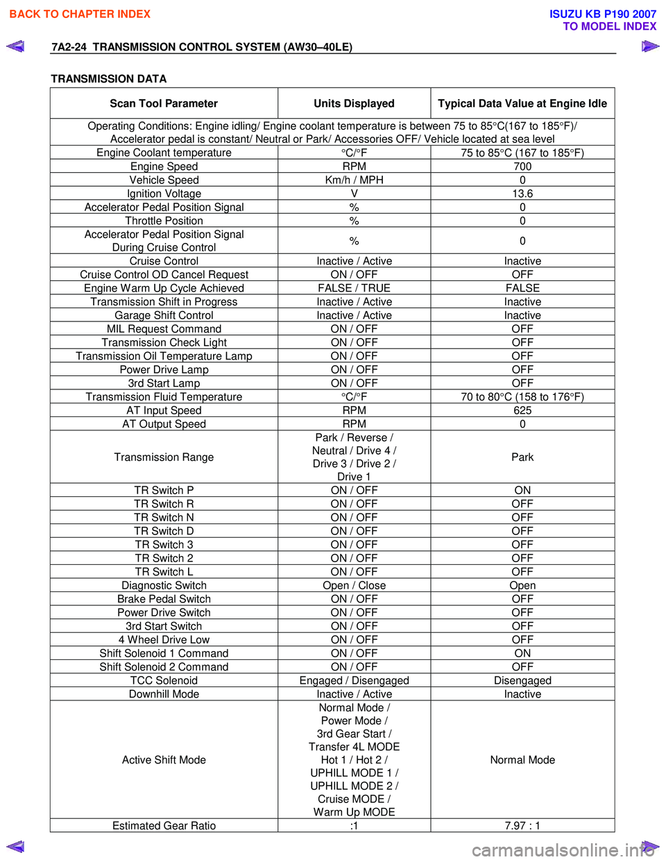
7A2-24 TRANSMISSION CONTROL SYSTEM (AW30–40LE)
TRANSMISSION DATA
Scan Tool Parameter Units Displayed Typical Data Value at Engine Idle
Operating Conditions: Engine idling/ Engine coolant temperature is between 75 to 85 °C(167 to 185 °F)/
Accelerator pedal is constant/ Neutral or Park/ Accessories OFF/ Vehicle located at sea level
Engine Coolant temperature °C/ °F 75 to 85°C (167 to 185 °F)
Engine Speed RPM 700
Vehicle Speed Km/h / MPH 0
Ignition Voltage V 13.6
Accelerator Pedal Position Signal % 0
Throttle Position % 0
Accelerator Pedal Position Signal
During Cruise Control % 0
Cruise Control
Inactive / Active Inactive
Cruise Control OD Cancel Request ON / OFF OFF
Engine W arm Up Cycle Achieved FALSE / TRUE FALSE
Transmission Shift in Progress Inactive / Active Inactive
Garage Shift Control Inactive / Active Inactive
MIL Request Command ON / OFF OFF
Transmission Check Light ON / OFF OFF
Transmission Oil Temperature Lamp ON / OFF OFF
Power Drive Lamp ON / OFF OFF
3rd Start Lamp ON / OFF OFF
Transmission Fluid Temperature
°C/ °F 70 to 80°C (158 to 176 °F)
AT Input Speed RPM 625
AT Output Speed RPM 0
Transmission Range Park / Reverse /
Neutral / Drive 4 / Drive 3 / Drive 2 / Drive 1 Park
TR Switch P
ON / OFF ON
TR Switch R ON / OFF OFF
TR Switch N ON / OFF OFF
TR Switch D ON / OFF OFF
TR Switch 3 ON / OFF OFF
TR Switch 2 ON / OFF OFF
TR Switch L ON / OFF OFF
Diagnostic Switch Open / Close Open
Brake Pedal Switch ON / OFF OFF
Power Drive Switch ON / OFF OFF
3rd Start Switch ON / OFF OFF
4 W heel Drive Low ON / OFF OFF
Shift Solenoid 1 Command ON / OFF ON
Shift Solenoid 2 Command ON / OFF OFF
TCC Solenoid Engaged / Disengaged Disengaged
Downhill Mode Inactive / Active Inactive
Active Shift Mode Normal Mode /
Power Mode /
3rd Gear Start /
Transfer 4L MODE Hot 1 / Hot 2 /
UPHILL MODE 1 /
UPHILL MODE 2 / Cruise MODE /
W arm Up MODE Normal Mode
Estimated Gear Ratio
:1 7.97 : 1
BACK TO CHAPTER INDEX
TO MODEL INDEX
ISUZU KB P190 2007
Page 4016 of 6020
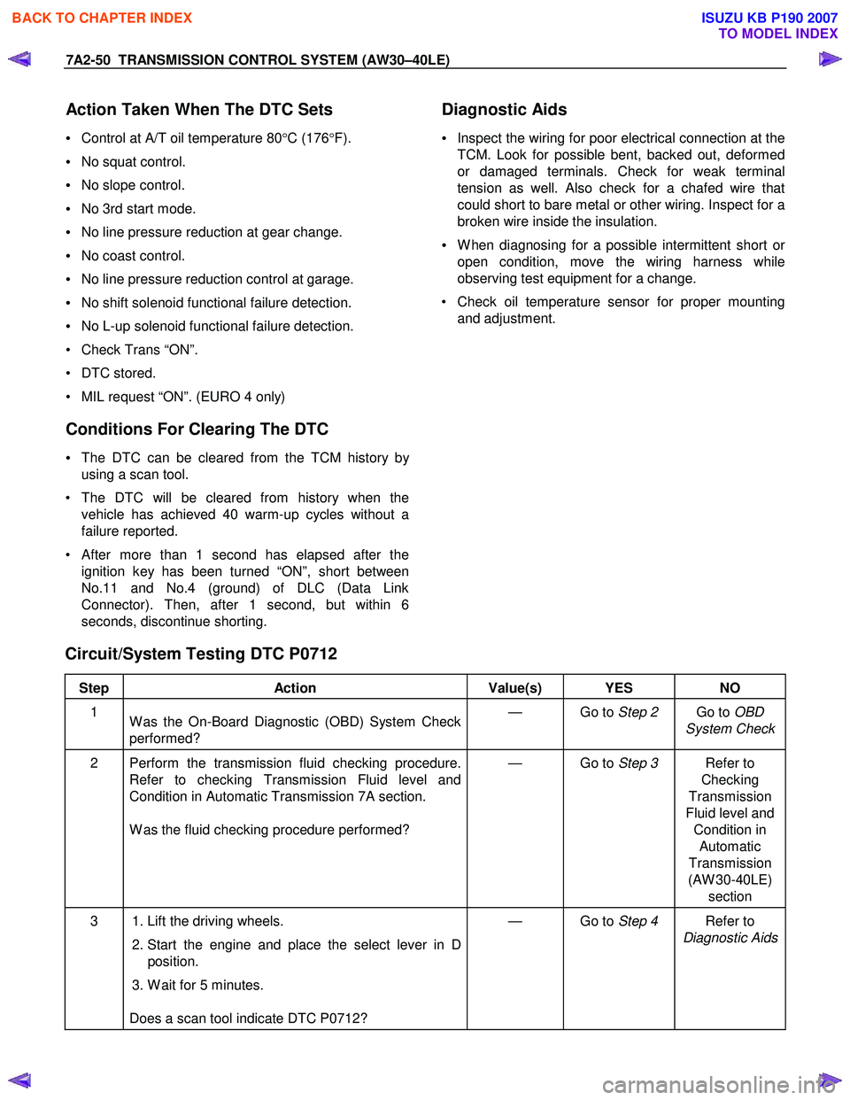
7A2-50 TRANSMISSION CONTROL SYSTEM (AW30–40LE)
Action Taken When The DTC Sets
• Control at A/T oil temperature 80 °C (176 °F).
• No squat control.
• No slope control.
• No 3rd start mode.
• No line pressure reduction at gear change.
• No coast control.
• No line pressure reduction control at garage.
• No shift solenoid functional failure detection.
• No L-up solenoid functional failure detection.
• Check Trans “ON”.
• DTC stored.
• MIL request “ON”. (EURO 4 only)
Conditions For Clearing The DTC
• The DTC can be cleared from the TCM history by
using a scan tool.
• The DTC will be cleared from history when the vehicle has achieved 40 warm-up cycles without a
failure reported.
•
After more than 1 second has elapsed after the
ignition key has been turned “ON”, short between
No.11 and No.4 (ground) of DLC (Data Link
Connector). Then, after 1 second, but within 6
seconds, discontinue shorting.
Diagnostic Aids
•
Inspect the wiring for poor electrical connection at the
TCM. Look for possible bent, backed out, deformed
or damaged terminals. Check for weak terminal
tension as well. Also check for a chafed wire that
could short to bare metal or other wiring. Inspect for a
broken wire inside the insulation.
• W hen diagnosing for a possible intermittent short o
r
open condition, move the wiring harness while
observing test equipment for a change.
• Check oil temperature sensor for proper mounting and adjustment.
Circuit/System Testing DTC P0712
Step Action Value(s) YES NO
1
W as the On-Board Diagnostic (OBD) System Check
performed? — Go to
Step 2 Go to OBD
System Check
2 Perform the transmission fluid checking procedure. Refer to checking Transmission Fluid level and
Condition in Automatic Transmission 7A section.
W as the fluid checking procedure performed? — Go to
Step 3 Refer to
Checking
Transmission
Fluid level and Condition in Automatic
Transmission
(AW 30-40LE) section
3 1. Lift the driving wheels.
2. Start the engine and place the select lever in D
position.
3. W ait for 5 minutes.
Does a scan tool indicate DTC P0712? — Go to
Step 4 Refer to
Diagnostic Aids
BACK TO CHAPTER INDEX
TO MODEL INDEX
ISUZU KB P190 2007
Page 4019 of 6020
TRANSMISSION CONTROL SYSTEM (AW30–40LE) 7A2-53
• No L-up solenoid functional failure detection.
• Check Trans “ON”.
• DTC stored.
• MIL request “ON”. (EURO 4 only)
Conditions For Clearing The DTC
• The DTC can be cleared from the TCM history by
using a scan tool.
• The DTC will be cleared from history when the
vehicle has achieved 40 warm-up cycles without a
failure reported.
•
After more than 1 second has elapsed after the
ignition key has been turned “ON”, short between
No.11 and No.4 (ground) of DLC (Data Link
Connector). Then, after 1 second, but within 6
seconds, discontinue shorting.
Diagnostic Aids
•
Inspect the wiring for poor electrical connection at the
TCM. Look for possible bent, backed out, deformed
or damaged terminals. Check for weak terminal
tension as well. Also check for a chafed wire that
could short to bare metal or other wiring. Inspect for a
broken wire inside the insulation.
• W hen diagnosing for a possible intermittent short o
r
open condition, move the wiring harness while
observing test equipment for a change.
• Check oil temperature sensor for proper mounting
and adjustment.
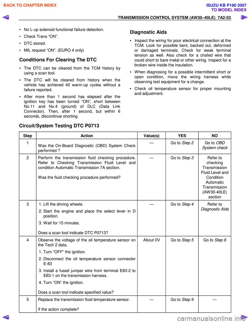
Circuit/System Testing DTC P0713
Step Action Value(s) YES NO
1
W as the On-Board Diagnostic (OBD) System Check
performed ? — Go to
Step 2 Go to OBD
System check
2 Perform the transmission fluid checking procedure. Refer to Checking Transmission Fluid Level and
condition Automatic Transmission 7A section.
W as the fluid checking procedure performed? — Go to
Step 3 Refer to
checking
Transmission
Fluid Level and Condition
Automatic
Transmission
(AW 30-40LE) section
3 1. Lift the driving wheels.
2. Start the engine and place the select lever in D
position.
3. W ait for 15 minutes.
Does a scan tool indicate DTC P0713? — Go to
Step 4 Refer to
Diagnostic Aids
4 Observe the voltage of the oil temperature sensor on the Tech 2 data.
1. Turn “OFF” the ignition.
2. Disconnect the oil temperature sensor connector
E-83
3. Install a fused jumper wire from terminal E83-2 to E83-1 on the transmission harness.
4. Turn “ON” the ignition.
Does a scan tool indicate specified value? About 0V Go to
Step 5 Go to Step 6
5 Replace the transmission fluid temperature sensor.
If the action complete? — Go to
Step 9 —
BACK TO CHAPTER INDEX
TO MODEL INDEX
ISUZU KB P190 2007
Page 4031 of 6020
TRANSMISSION CONTROL SYSTEM (AW30–40LE) 7A2-65
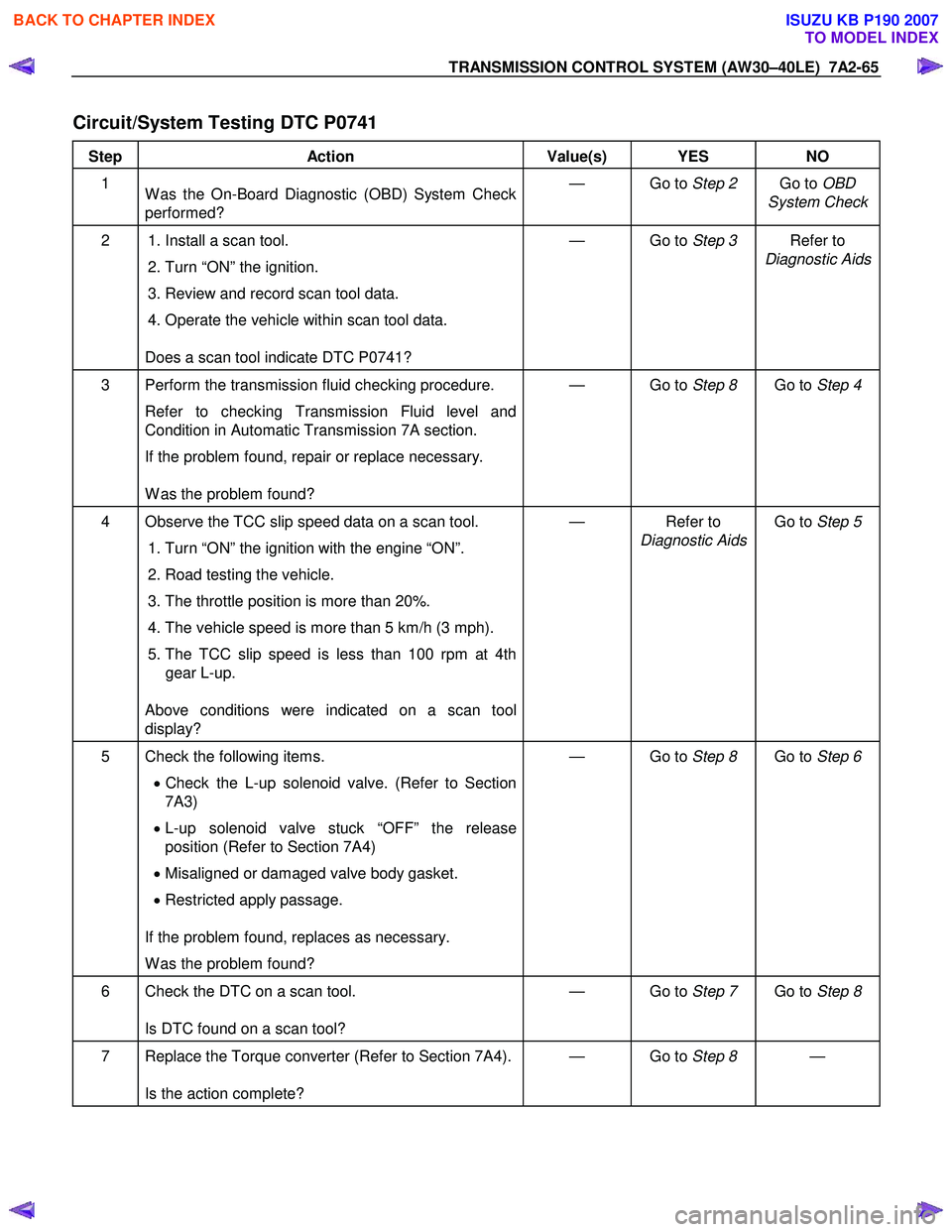
Circuit/System Testing DTC P0741
Step Action Value(s) YES NO
1
W as the On-Board Diagnostic (OBD) System Check
performed? — Go to
Step 2 Go to OBD
System Check
2 1. Install a scan tool.
2. Turn “ON” the ignition.
3. Review and record scan tool data.
4. Operate the vehicle within scan tool data.
Does a scan tool indicate DTC P0741? — Go to
Step 3 Refer to
Diagnostic Aids
3 Perform the transmission fluid checking procedure.
Refer to checking Transmission Fluid level and
Condition in Automatic Transmission 7A section.
If the problem found, repair or replace necessary.
W as the problem found? — Go to
Step 8 Go to Step 4
4 Observe the TCC slip speed data on a scan tool.
1. Turn “ON” the ignition with the engine “ON”.
2. Road testing the vehicle.
3. The throttle position is more than 20%.
4. The vehicle speed is more than 5 km/h (3 mph).
5. The TCC slip speed is less than 100 rpm at 4th gear L-up.
Above conditions were indicated on a scan tool
display? — Refer to
Diagnostic Aids Go to
Step 5
5 Check the following items.
• Check the L-up solenoid valve. (Refer to Section
7A3)
• L-up solenoid valve stuck “OFF” the release
position (Refer to Section 7A4)
• Misaligned or damaged valve body gasket.
• Restricted apply passage.
If the problem found, replaces as necessary.
W as the problem found? — Go to
Step 8 Go to Step 6
6 Check the DTC on a scan tool.
Is DTC found on a scan tool? — Go to
Step 7 Go to Step 8
7 Replace the Torque converter (Refer to Section 7A4).
Is the action complete? — Go to
Step 8 —
BACK TO CHAPTER INDEX
TO MODEL INDEX
ISUZU KB P190 2007