2007 ISUZU KB P190 check transmission fluid
[x] Cancel search: check transmission fluidPage 4103 of 6020
7A3-18 ON-VEHICLE SERVICE (AW30–40LE)
Transmission Fluid Level and Condition
Inspection
Park vehicle on level ground and set parking brake.
W ith the engine idling, move the shift lever through all
positions from “P" to “L", then return to position “P".
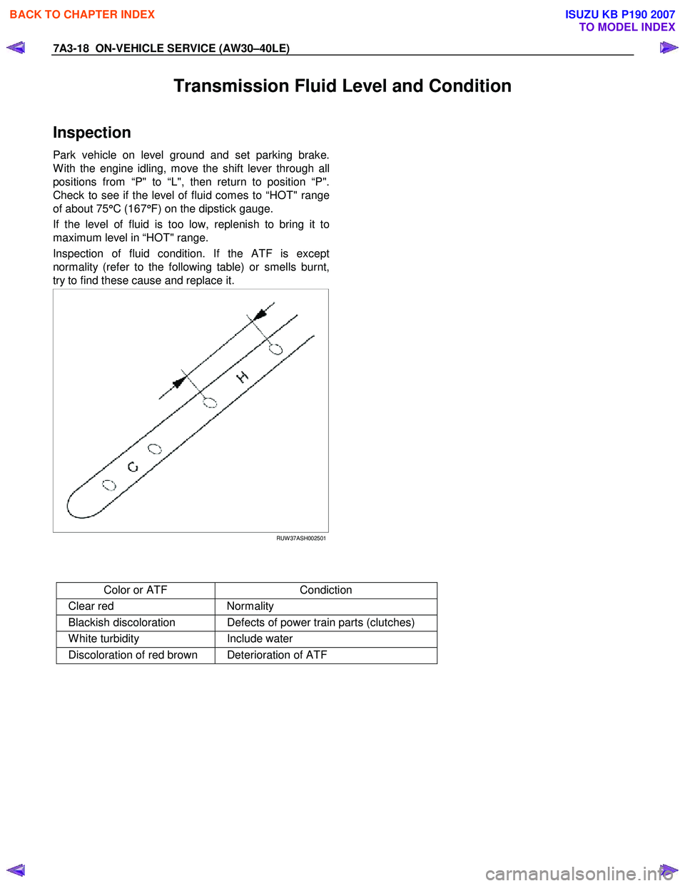
Check to see if the level of fluid comes to “HOT" range
of about 75 °
°°
°
C (167 °
°°
°
F) on the dipstick gauge.
If the level of fluid is too low, replenish to bring it to
maximum level in “HOT" range.
Inspection of fluid condition. If the ATF is except
normality (refer to the following table) or smells burnt,
try to find these cause and replace it.
RUW 37ASH002501
Color or ATF Condiction
Clear red Normality
Blackish discoloration Defects of power train parts (clutches)
W hite turbidity Include water
Discoloration of red brown Deterioration of ATF
BACK TO CHAPTER INDEX
TO MODEL INDEX
ISUZU KB P190 2007
Page 4171 of 6020
7A4–36 UNIT REPAIR (AW30–40LE)
Diaassembly, Inspection and
Reassembly of minor Components
NOTE: The instructions here are organized so that you
work on only one component group at a time.
This will help avoid confusion from similar-looking parts
of different subassemblies being on your workbench at
the same time.
The component groups are inspected and repaired from
the converter housing side.
As much as possible, complete the inspection, repair
and reassembly before proceeding to the next
component group. If a component group cannot be
reassembled because parts are being ordered, be sure
to keep all parts of that group in separate container
while proceeding with disassembly, inspection, repair
and reassembly of other component groups.
Recommended ATF type DEXRON III.
General Cleaning Notes:
1. All disassembled parts should be washed clean and any fluid passages and holes should be blown
through with compressed air.
2. When using compressed air to dry parts, always aim away from yourself to prevent accidentally spraying
automatic transmission fluid in your face.
3. The recommended automatic transmission fluid should be used for cleaning.
Parts Arrangement:
1. After cleaning, the parts should be arranged inproper order to allow performing inspection, repairs,
and reassembly with efficiency.
2. When disassembling a valve body, be sure to keep each valve together with the corresponding spring.
3. New brakes and clutches that are to be used for replacement must be soaked in transmission fluid
for at least thirty minutes before assembly.
General Assembly:
1. All oil seal rings, clutch discs, clutch plates, rotating parts, and sliding surfaces should be coated with
transmission fluid prior to reassembly.
2. All gaskets and rubber O-ring should be replaced.
3. Make sure that the ends of a snap ring are not aligned with one of the cutouts and are installed in
the groove correctly.
4. If a worn bushing is to be replaced, the subassembly containing that bushing must be
replaced.
5. Check thrust bearings and races for wear or damage. Replace if necessary.
6. Use petroleum jelly or vaseline to keep parts in place.
BACK TO CHAPTER INDEX
TO MODEL INDEX
ISUZU KB P190 2007
Page 4285 of 6020

TRANSMISSION CONTROL SYSTEM (JR405E) 7A2-1
TRANSMISSION
TRANSMISSION CONTROL SYSTEM (JR405E)
This manual conforms when Scan Tool of ISO CAN Base Software is used.
TABLE OF CONTENTS
Specifications ...................................................... 7A2-2Transmission General Specifications ............... 7A2-2
Transmission Fluid Temperature vs. Resistance..... 7A2-3
Clutch, Brake, Solenoid and Pressure Switch Logic........ 7A2-4
Diagnostic Trouble Code (DTC) List ................ 7A2-5
Schematic and Routing Diagrams....................... 7A2-6 Transmission Controls Schematics .................. 7A2-6
Component Locator........................................... 7A2-13 Transmission Controls Component Views ..... 7A2-13
Transmission Control Module (TCM) Connector End Views ................................... 7A2-17
Transmission Control Connector End Views.. 7A2-18
Diagnostic Information and Procedures ............ 7A2-21
Diagnostic Starting Point - Transmission Controls......... 7A2-21
Diagnostic System Check - Transmission Controls....... 7A2-22
Scan Tool Data List ........................................ 7A2-24
Scan Tool Data Definitions............................. 7A2-25
Scan Tool Output Controls ............................. 7A2-27
Scan Tool Does Not Power Up ...................... 7A2-28
Scan Tool Does Not Communicate with Keyword Device .................................... 7A2-29
Lost Communication with The Transmission Control Module (TCM)
.... 7A2-31
DTC P0560 (Flash Code 16).......................... 7A2-33
DTC P0602 .................................................... 7A2-35
DTC P0705 (Flash Code 17).......................... 7A2-36
DTC P0710 (Flash Code 15).......................... 7A2-40
DTC P0717 (Flash Code 14).......................... 7A2-44
DTC P0722 (Flash Code 11).......................... 7A2-47
DTC P0727 (Flash Code 13).......................... 7A2-50
DTC P0731, P0732, P0733 or P0734 (Flash Code 41, 42, 43 or 44)....................... 7A2-52
DTC P0748 (Flash Code 35).......................... 7A2-55
DTC P0753 (Flash Code 31).......................... 7A2-58
DTC P0758 (Flash Code 32).......................... 7A2-61
DTC P0763 (Flash Code 33).......................... 7A2-64
DTC P0768 (Flash Code 34).......................... 7A2-67
DTC P1120 (Flash Code 22).......................... 7A2-70
DTC P1750 (Flash Code 51).......................... 7A2-71
DTC P1755 (Flash Code 52).......................... 7A2-73
DTC P1853 (Flash Code 26).......................... 7A2-75
DTC P1858 (Flash Code 27).......................... 7A2-78
DTC P1860 (Flash Code 36).......................... 7A2-81
DTC P1863 (Flash Code 28).......................... 7A2-84
DTC P1875 (Flash Code 25).......................... 7A2-87
Check Trans Lamp Inoperative, Always On or Always Blinking ...................... 7A2-89
Symptoms - Transmission Controls .................. 7A2-92 Symptoms - Transmission Controls ............... 7A2-92
Intermittent Conditions ................................... 7A2-93 Vehicle Does Not Run .................................... 7A2-95
Trouble at Starting.......................................... 7A2-95
Faulty Gearshift .............................................. 7A2-95
Faulty Shift Pattern......................................... 7A2-95
No or Error Gearshift ...................................... 7A2-95
Faulty Operation During Running................... 7A2-95
Faulty Operation in Stopping.......................... 7A2-95
Faulty Lock Up ............................................... 7A2-95
No Lock Up .................................................... 7A2-95
Transmission Fluid Leak ................................ 7A2-95
Others ............................................................ 7A2-95
Test Instructions .............................................. 7A2-121 Line Pressure Test ....................................... 7A2-121
Stall Test ...................................................... 7A2-123
Time Lag Test .............................................. 7A2-124
Road Test..................................................... 7A2-125
TCM Signal Test .......................................... 7A2-134
Repair Instructions .......................................... 7A2-139
Transmission Controls Module (TCM) Replacement.... 7A2-139
Service Programming System (SPS) Description........ 7A2-139
Service Programming System (SPS) (Remote Procedure)......................... 7A2-140
Service Programming System (SPS) (Pass-Thru Procedure)..................... 7A2-141
Description and Operation .............................. 7A2-143 Transmission Identification Information........ 7A2-143
Transmission General Description ............... 7A2-143
Transmission Component Description ......... 7A2-144
Transmission Control System Description ... 7A2-152
Transmission Power Flow Description ......... 7A2-161
Special Tools and Equipment ......................... 7A2-170 Special Tools and Equipment ...................... 7A2-170
BACK TO CHAPTER INDEX
TO MODEL INDEX
ISUZU KB P190 2007
Page 4299 of 6020
TRANSMISSION CONTROL SYSTEM (JR405E) 7A2-15
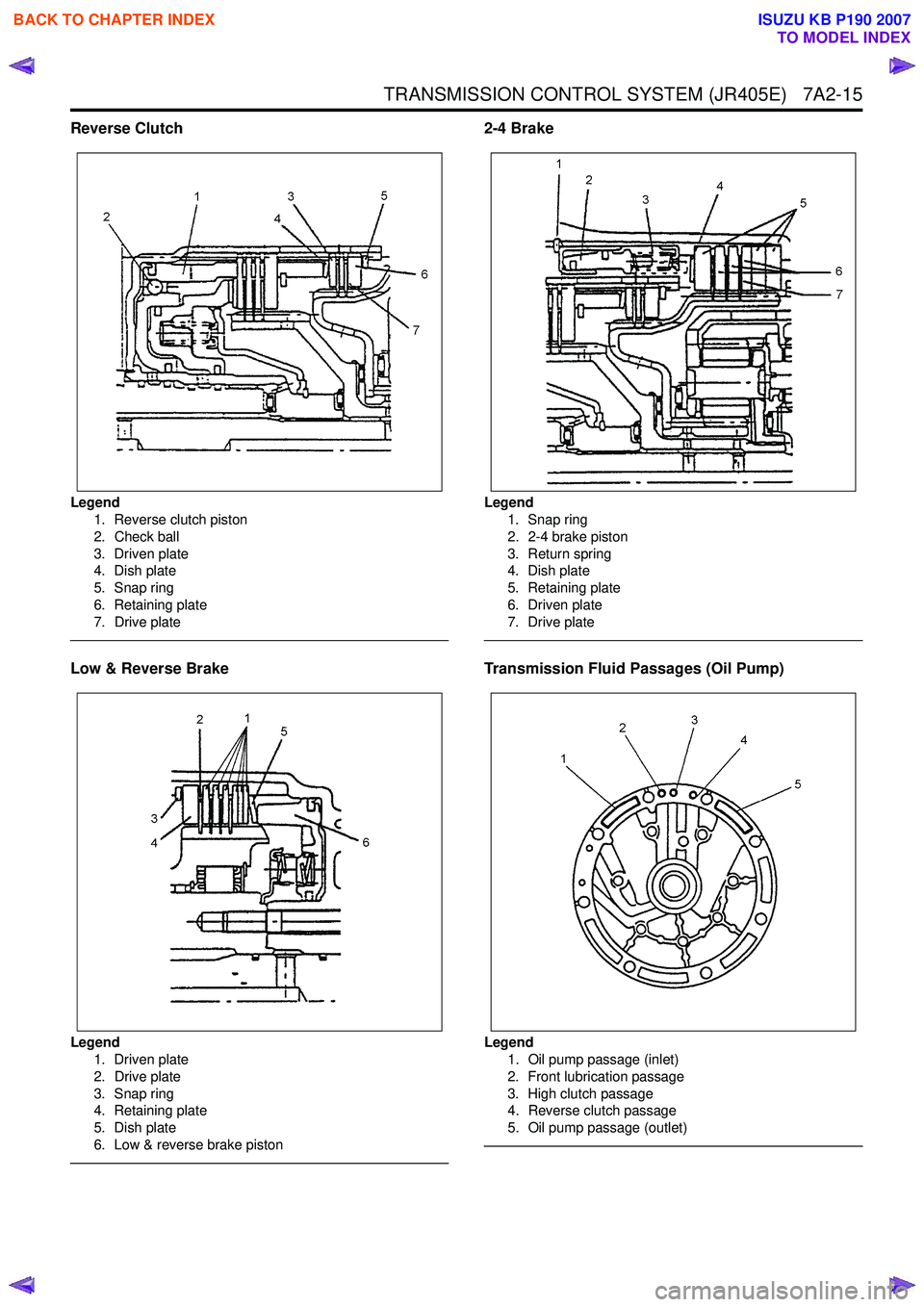
Reverse Clutch
Legend1. Reverse clutch piston
2. Check ball
3. Driven plate
4. Dish plate
5. Snap ring
6. Retaining plate
7. Drive plate
Low & Reverse Brake
Legend 1. Driven plate
2. Drive plate
3. Snap ring
4. Retaining plate
5. Dish plate
6. Low & reverse brake piston
2-4 Brake
Legend 1. Snap ring
2. 2-4 brake piston
3. Return spring
4. Dish plate
5. Retaining plate
6. Driven plate
7. Drive plate
Transmission Fluid Passages (Oil Pump)
Legend 1. Oil pump passage (inlet)
2. Front lubrication passage
3. High clutch passage
4. Reverse clutch passage
5. Oil pump passage (outlet)
BACK TO CHAPTER INDEX
TO MODEL INDEX
ISUZU KB P190 2007
Page 4308 of 6020
7A2-24 TRANSMISSION CONTROL SYSTEM (JR405E)
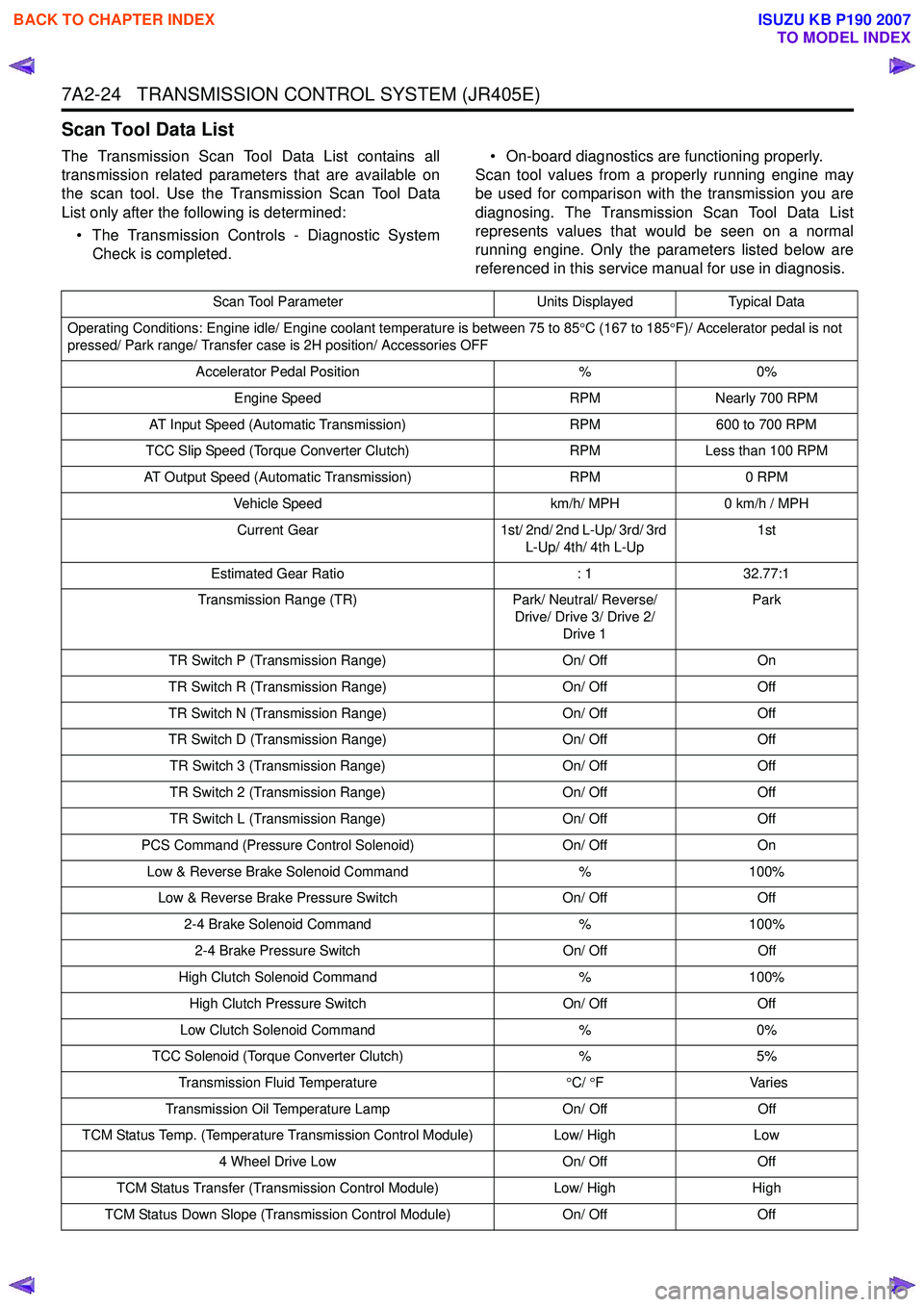
Scan Tool Data List
The Transmission Scan Tool Data List contains all
transmission related parameters that are available on
the scan tool. Use the Transmission Scan Tool Data
List only after the following is determined:
• The Transmission Controls - Diagnostic System Check is completed. • On-board diagnostics are functioning properly.
Scan tool values from a properly running engine may
be used for comparison with the transmission you are
diagnosing. The Transmission Scan Tool Data List
represents values that would be seen on a normal
running engine. Only the parameters listed below are
referenced in this service manual for use in diagnosis.
Scan Tool Parameter Units DisplayedTypical Data
Operating Conditions: Engine idle/ Engine coolant temperature is between 75 to 85 °C (167 to 185 °F)/ Accelerator pedal is not
pressed/ Park range/ Transfer case is 2H position/ Accessories OFF
Accelerator Pedal Position %0%
Engine Speed RPMNearly 700 RPM
AT Input Speed (Automatic Transmission) RPM600 to 700 RPM
TCC Slip Speed (Torque Converter Clutch) RPMLess than 100 RPM
AT Output Speed (Automatic Transmission) RPM0 RPM
Vehicle Speed km/h/ MPH0 km/h / MPH
Current Gear 1st/ 2nd/ 2nd L-Up/ 3rd/ 3rd
L-Up/ 4th/ 4th L-Up 1st
Estimated Gear Ratio : 132.77:1
Transmission Range (TR) Park/ Neutral/ Reverse/
Drive/ Drive 3/ Drive 2/ Drive 1 Park
TR Switch P (Transmission Range) On/ OffOn
TR Switch R (Transmission Range) On/ OffOff
TR Switch N (Transmission Range) On/ OffOff
TR Switch D (Transmission Range) On/ OffOff
TR Switch 3 (Transmission Range) On/ OffOff
TR Switch 2 (Transmission Range) On/ OffOff
TR Switch L (Transmission Range) On/ OffOff
PCS Command (Pressure Control Solenoid) On/ OffOn
Low & Reverse Brake Solenoid Command %100%
Low & Reverse Brake Pressure Switch On/ OffOff
2-4 Brake Solenoid Command %100%
2-4 Brake Pressure Switch On/ OffOff
High Clutch Solenoid Command %100%
High Clutch Pressure Switch On/ OffOff
Low Clutch Solenoid Command %0%
TCC Solenoid (Torque Converter Clutch) %5%
Transmission Fluid Temperature °C/ °F V arie s
Transmission Oil Temperature Lamp On/ OffOff
TCM Status Temp. (Temperature Transmission Control Module) Low/ HighLow
4 Wheel Drive Low On/ OffOff
TCM Status Transfer (Transmission Control Module) Low/ HighHigh
TCM Status Down Slope (Transmission Control Module) On/ OffOff
BACK TO CHAPTER INDEX
TO MODEL INDEX
ISUZU KB P190 2007
Page 4309 of 6020
TRANSMISSION CONTROL SYSTEM (JR405E) 7A2-25
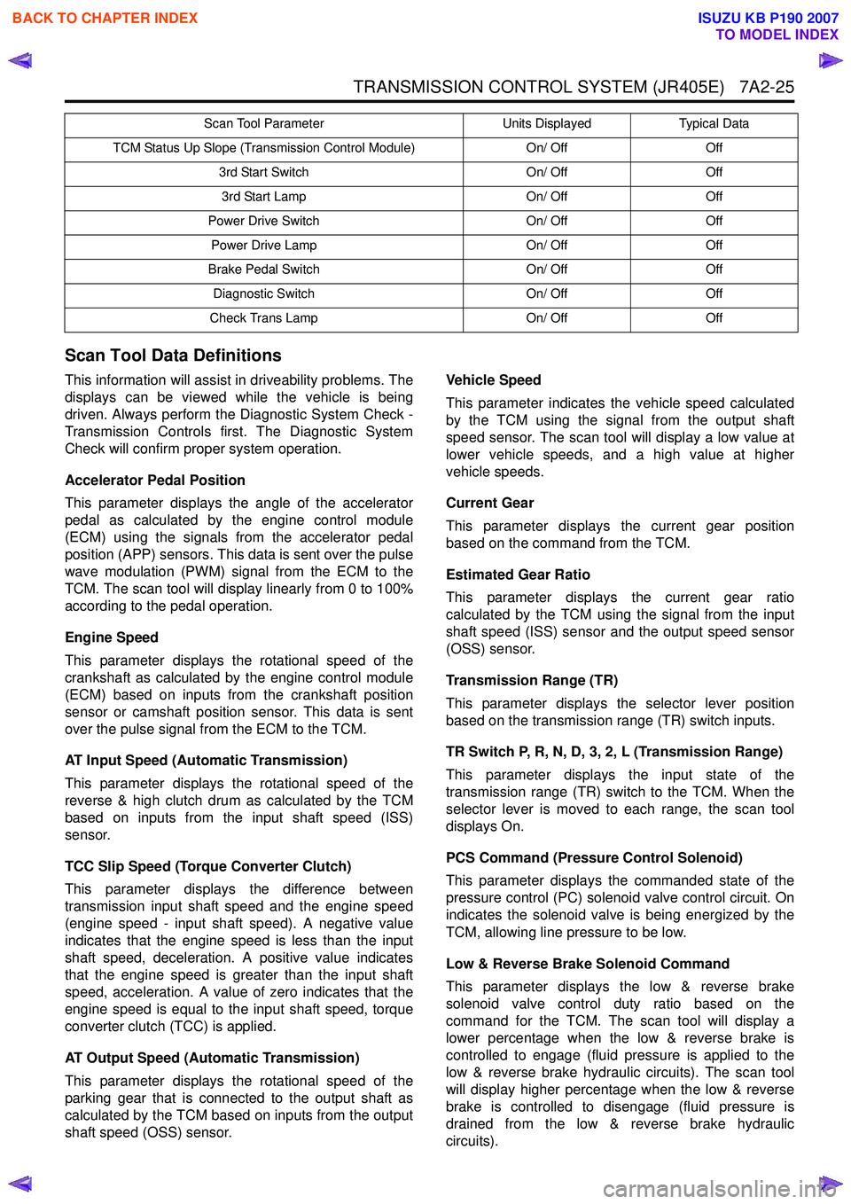
Scan Tool Data Definitions
This information will assist in driveability problems. The
displays can be viewed while the vehicle is being
driven. Always perform the Diagnostic System Check -
Transmission Controls first. The Diagnostic System
Check will confirm proper system operation.
Accelerator Pedal Position
This parameter displays the angle of the accelerator
pedal as calculated by the engine control module
(ECM) using the signals from the accelerator pedal
position (APP) sensors. This data is sent over the pulse
wave modulation (PWM) signal from the ECM to the
TCM. The scan tool will display linearly from 0 to 100%
according to the pedal operation.
Engine Speed
This parameter displays the rotational speed of the
crankshaft as calculated by the engine control module
(ECM) based on inputs from the crankshaft position
sensor or camshaft position sensor. This data is sent
over the pulse signal from the ECM to the TCM.
AT Input Speed (Automatic Transmission)
This parameter displays the rotational speed of the
reverse & high clutch drum as calculated by the TCM
based on inputs from the input shaft speed (ISS)
sensor.
TCC Slip Speed (Torque Converter Clutch)
This parameter displays the difference between
transmission input shaft speed and the engine speed
(engine speed - input shaft speed). A negative value
indicates that the engine speed is less than the input
shaft speed, deceleration. A positive value indicates
that the engine speed is greater than the input shaft
speed, acceleration. A value of zero indicates that the
engine speed is equal to the input shaft speed, torque
converter clutch (TCC) is applied.
AT Output Speed (Automatic Transmission)
This parameter displays the rotational speed of the
parking gear that is connected to the output shaft as
calculated by the TCM based on inputs from the output
shaft speed (OSS) sensor. Vehicle Speed
This parameter indicates the vehicle speed calculated
by the TCM using the signal from the output shaft
speed sensor. The scan tool will display a low value at
lower vehicle speeds, and a high value at higher
vehicle speeds.
Current Gear
This parameter displays the current gear position
based on the command from the TCM.
Estimated Gear Ratio
This parameter displays the current gear ratio
calculated by the TCM using the signal from the input
shaft speed (ISS) sensor and the output speed sensor
(OSS) sensor.
Transmission Range (TR)
This parameter displays the selector lever position
based on the transmission range (TR) switch inputs.
TR Switch P, R, N, D, 3, 2, L (Transmission Range)
This parameter displays the input state of the
transmission range (TR) switch to the TCM. When the
selector lever is moved to each range, the scan tool
displays On.
PCS Command (Pressure Control Solenoid)
This parameter displays the commanded state of the
pressure control (PC) solenoid valve control circuit. On
indicates the solenoid valve is being energized by the
TCM, allowing line pressure to be low.
Low & Reverse Brake Solenoid Command
This parameter displays the low & reverse brake
solenoid valve control duty ratio based on the
command for the TCM. The scan tool will display a
lower percentage when the low & reverse brake is
controlled to engage (fluid pressure is applied to the
low & reverse brake hydraulic circuits). The scan tool
will display higher percentage when the low & reverse
brake is controlled to disengage (fluid pressure is
drained from the low & reverse brake hydraulic
circuits).
TCM Status Up Slope (Transmission Control Module) On/ OffOff
3rd Start Switch On/ OffOff
3rd Start Lamp On/ OffOff
Power Drive Switch On/ OffOff
Power Drive Lamp On/ OffOff
Brake Pedal Switch On/ OffOff
Diagnostic Switch On/ OffOff
Check Trans Lamp On/ OffOff
Scan Tool Parameter
Units DisplayedTypical Data
BACK TO CHAPTER INDEX
TO MODEL INDEX
ISUZU KB P190 2007
Page 4324 of 6020
7A2-40 TRANSMISSION CONTROL SYSTEM (JR405E)
DTC P0710 (Flash Code 15)
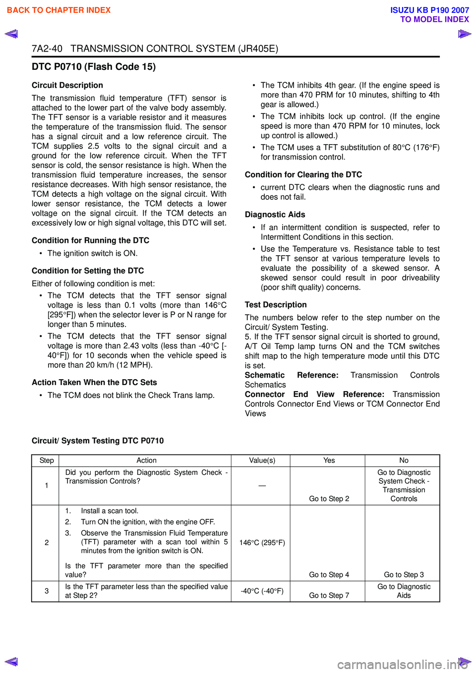
Circuit Description
The transmission fluid temperature (TFT) sensor is
attached to the lower part of the valve body assembly.
The TFT sensor is a variable resistor and it measures
the temperature of the transmission fluid. The sensor
has a signal circuit and a low reference circuit. The
TCM supplies 2.5 volts to the signal circuit and a
ground for the low reference circuit. When the TFT
sensor is cold, the sensor resistance is high. When the
transmission fluid temperature increases, the sensor
resistance decreases. With high sensor resistance, the
TCM detects a high voltage on the signal circuit. With
lower sensor resistance, the TCM detects a lower
voltage on the signal circuit. If the TCM detects an
excessively low or high signal voltage, this DTC will set.
Condition for Running the DTC • The ignition switch is ON.
Condition for Setting the DTC
Either of following condition is met: • The TCM detects that the TFT sensor signal voltage is less than 0.1 volts (more than 146 °C
[295 °F]) when the selector lever is P or N range for
longer than 5 minutes.
• The TCM detects that the TFT sensor signal voltage is more than 2.43 volts (less than -40 °C [-
40 °F]) for 10 seconds when the vehicle speed is
more than 20 km/h (12 MPH).
Action Taken When the DTC Sets • The TCM does not blink the Check Trans lamp. • The TCM inhibits 4th gear. (If the engine speed is
more than 470 PRM for 10 minutes, shifting to 4th
gear is allowed.)
• The TCM inhibits lock up control. (If the engine speed is more than 470 RPM for 10 minutes, lock
up control is allowed.)
• The TCM uses a TFT substitution of 80 °C (176 °F)
for transmission control.
Condition for Clearing the DTC • current DTC clears when the diagnostic runs and does not fail.
Diagnostic Aids • If an intermittent condition is suspected, refer to Intermittent Conditions in this section.
• Use the Temperature vs. Resistance table to test the TFT sensor at various temperature levels to
evaluate the possibility of a skewed sensor. A
skewed sensor could result in poor driveability
(poor shift quality) concerns.
Test Description
The numbers below refer to the step number on the
Circuit/ System Testing.
5. If the TFT sensor signal circuit is shorted to ground,
A/T Oil Temp lamp turns ON and the TCM switches
shift map to the high temperature mode until this DTC
is set.
Schematic Reference: Transmission Controls
Schematics
Connector End View Reference: Transmission
Controls Connector End Views or TCM Connector End
Views
Circuit/ System Testing DTC P0710
Step Action Value(s)Yes No
1 Did you perform the Diagnostic System Check -
Transmission Controls? —
Go to Step 2 Go to Diagnostic
System Check -
Transmission Controls
2 1. Install a scan tool.
2. Turn ON the ignition, with the engine OFF.
3. Observe the Transmission Fluid Temperature (TFT) parameter with a scan tool within 5
minutes from the ignition switch is ON.
Is the TFT parameter more than the specified
value? 146
°C (295 °F)
Go to Step 4 Go to Step 3
3 Is the TFT parameter less than the specified value
at Step 2? -40
°C (-40 °F)
Go to Step 7 Go to Diagnostic
Aids
BACK TO CHAPTER INDEX
TO MODEL INDEX
ISUZU KB P190 2007
Page 4336 of 6020
7A2-52 TRANSMISSION CONTROL SYSTEM (JR405E)
DTC P0731, P0732, P0733 or P0734 (Flash Code 41, 42, 43 or 44)
Circuit Description
The TCM calculates the gear ratio based on the input
shaft speed signal from the input shaft speed (ISS)
sensor and the output speed signal from the output
shaft speed (OSS) sensor. The TCM compares the
known transmission gear ratio to the calculated ratio for
the selected gear ranges. If the TCM detects an
unknown transmission gear ratio two consecutive
driving cycles, this DTC will set.
Condition for Running the DTC • Other than DTCs P0731, P0732, P0733 and P0734 are not set.
• The ignition switch is ON.
• The transmission fluid temperature is more than 60 °C (140 °F).
• The input shaft speed is more than 1000 RPM.
• The vehicle speed is more than 10 km/h (6 MPH).
• The selector lever is forward range for longer than 2 seconds.
• The TCM is not under gearshift control.
Condition for Setting the DTC • The TCM detects that the output shaft speed is more than 500 RPM over the calculated speed
(based on the input shaft speed and the gear ratio)
for 7 seconds after each gearshift has completed.
Action Taken When the DTC Sets • The TCM blinks the Check Trans lamp on the second consecutive driving cycle when the
diagnostic runs and fails.
Condition for Clearing the DTC • The TCM turns OFF the Check Trans lamp when the diagnostic runs and does not fail. • A current DTC clears when the diagnostic runs and
does not fail.
Diagnostic Aids • If an intermittent condition is suspected, refer to Intermittent Conditions in this section.
• Electromagnetic interference in the ISS sensor or OSS sensor circuits may set this DTC.
• An intermittent ISS sensor or OSS sensor signal pulse may set this DTC.
• Ensure the ISS sensor and OSS sensor is tight.
• Use the Clutch, Brake, Solenoid and Pressure Switch Logic table to verify each component works
properly within the selected gear range.
• A transmission mechanical problem will cause this DTC to set.
• Sticking or contamination of shift valves may cause intermittent incorrect gear ratios.
• If multiple incorrect gear ratio codes are set, problem in fluid pressure, low ATF level, plugged
filter or oil pump problem may exist.
Notice: • Each DTC agrees with the following gear positions.
- P0731: 1st gear
- P0732: 2nd gear
- P0733: 3rd gear
- P0734: 4th gear
Schematic Reference: Transmission Controls
Schematics
Connector End View Reference: Transmission
Controls Connector End Views or TCM Connector End
Views
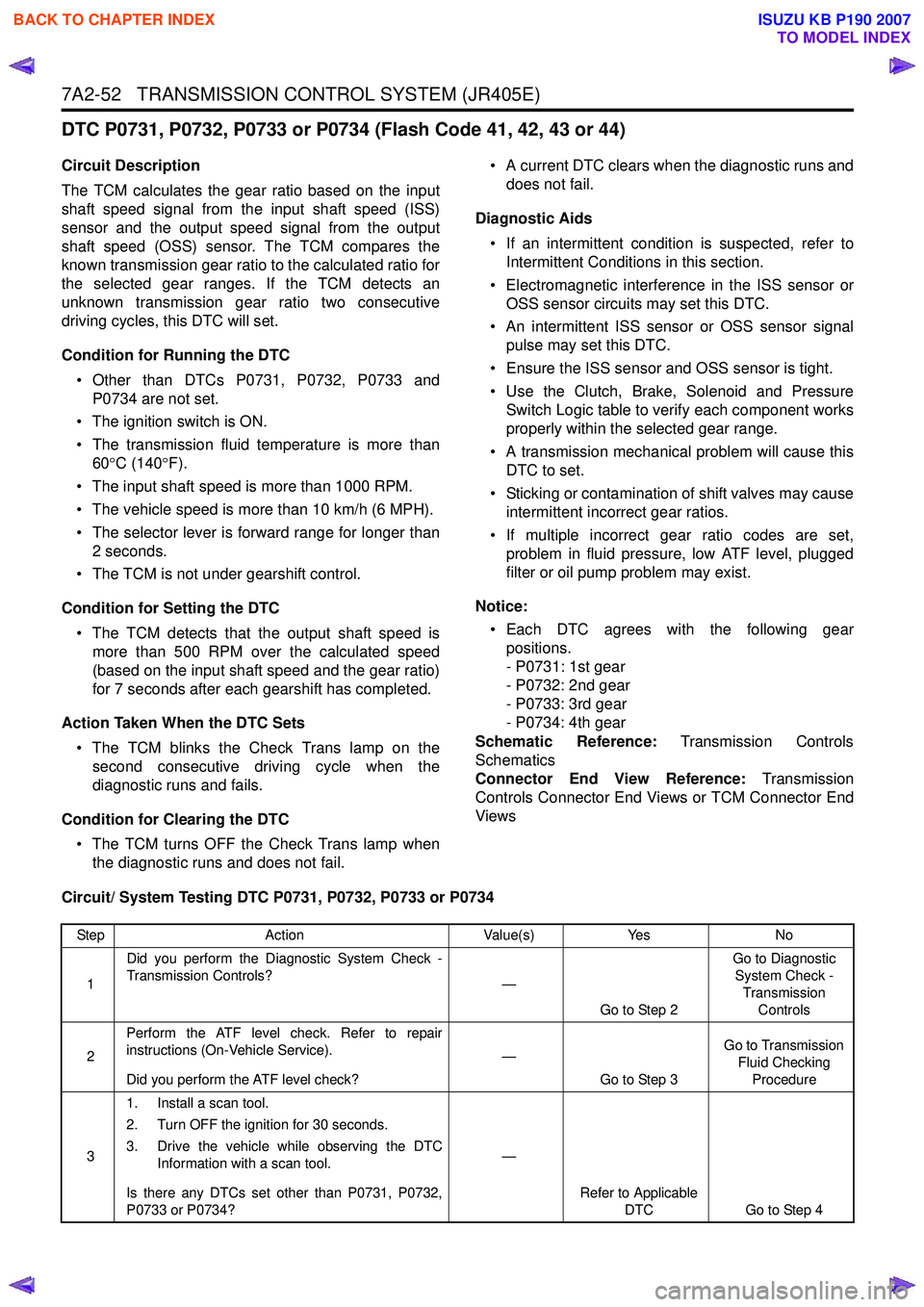
Circuit/ System Testing DTC P0731, P0732, P0733 or P0734
Step Action Value(s)Yes No
1 Did you perform the Diagnostic System Check -
Transmission Controls? —
Go to Step 2 Go to Diagnostic
System Check - Transmission Controls
2 Perform the ATF level check. Refer to repair
instructions (On-Vehicle Service).
Did you perform the ATF level check? —
Go to Step 3 Go to Transmission
Fluid Checking Procedure
3 1. Install a scan tool.
2. Turn OFF the ignition for 30 seconds.
3. Drive the vehicle while observing the DTC Information with a scan tool.
Is there any DTCs set other than P0731, P0732,
P0733 or P0734? —
Refer to Applicable DTC Go to Step 4
BACK TO CHAPTER INDEX
TO MODEL INDEX
ISUZU KB P190 2007