2007 ISUZU KB P190 sensor
[x] Cancel search: sensorPage 2261 of 6020
ENGINE DRIVEABILITY AND EMISSIONS 6E–91
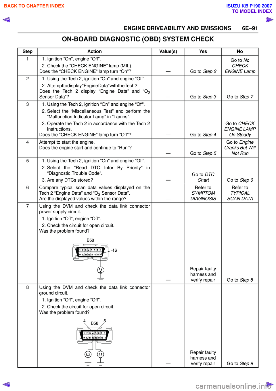
ON-BOARD DIAGNOSTIC (OBD) SYSTEM CHECK
StepAction Value(s) Yes No
1 1. Ignition “On”, engine “Off”. 2. Check the “CHECK ENGINE” lamp (MIL).
Does the “CHECK ENGINE” lamp turn “On”? — Go to Step 2Go to
No
CHECK
ENGINE Lamp
2 1. Using the Tech 2, ignition “On” and engine “Off”. 2 . A t t e m p t t o d i s p l a y “ E n g i n e D a t a ” w i t h t h e T e c h 2 .
Does the Tech 2 display “Engine Data” and “O
2Sensor Data”? — Go to Step 3Go to Step 7
3 1. Using the Tech 2, ignition “On” and engine “Off”. 2. Select the “Miscellaneous Test” and perform the“Malfunction Indicator Lamp” in “Lamps”.
3. Operate the Tech 2 in accordance with the Tech 2 instructions.
Does the “CHECK ENGINE” lamp turn “Off”? — Go to Step 4Go to
CHECK
ENGINE LAMP On Steady
4 Attempt to start the engine. Does the engine start and continue to “Run”? —Go to Step 5Go to
Engine
Cranks But Will Not Run
5 1. Using the Tech 2, ignition “On” and engine “Off”. 2. Select the “Read DTC Infor By Priority” in“Diagnostic Trouble Code”.
3. Are any DTCs stored? —Go to
DTC
Chart Go to Step 6
6 Compare typical scan data values displayed on the Tech 2 “Engine Data” and “O
2 Sensor Data”.
Are the displayed values within the range? —Refer to
SYMPTOM
DIAGNOSIS Refer to
TYPICAL
SCAN DATA
7 Using the DVM and check the data link connector power supply circuit.
1. Ignition “Off”, engine “Off”.
2. Check the circuit for open circuit.
Was the problem found?
—Repair faulty
harness and verify repair Go to Step 8
8 Using the DVM and check the data link connector ground circuit.
1. Ignition “Off”, engine “Off”.
2. Check the circuit for open circuit.
Was the problem found?
—Repair faulty
harness and verify repair Go to Step 9
V
16
B58
5
4B58
BACK TO CHAPTER INDEX
TO MODEL INDEX
ISUZU KB P190 2007
Page 2279 of 6020
ENGINE DRIVEABILITY AND EMISSIONS 6E–109
• The fuel injector(s).
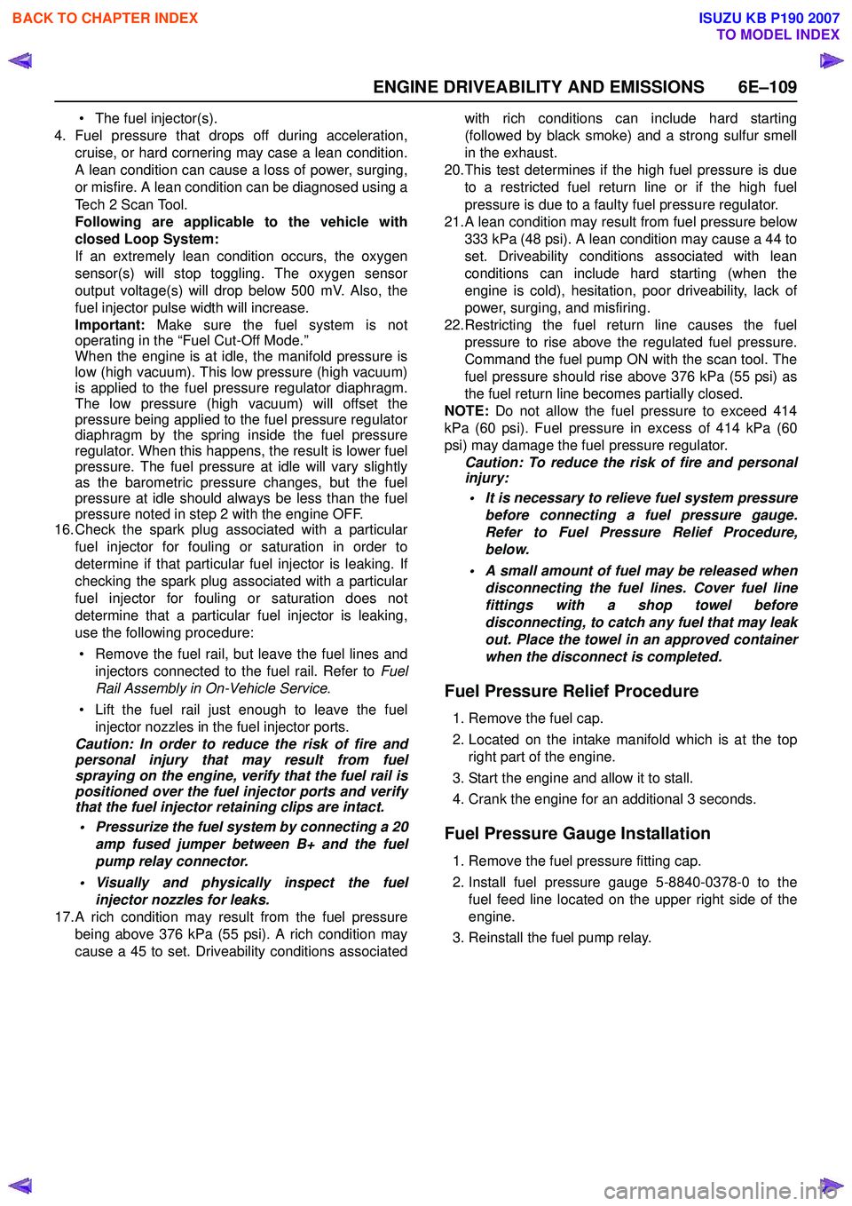
4. Fuel pressure that drops off during acceleration, cruise, or hard cornering may case a lean condition.
A lean condition can cause a loss of power, surging,
or misfire. A lean condition can be diagnosed using a
Tech 2 Scan Tool.
Following are applicable to the vehicle with
closed Loop System:
If an extremely lean condition occurs, the oxygen
sensor(s) will stop toggling. The oxygen sensor
output voltage(s) will drop below 500 mV. Also, the
fuel injector pulse width will increase.
Important: Make sure the fuel system is not
operating in the “Fuel Cut-Off Mode.”
When the engine is at idle, the manifold pressure is
low (high vacuum). This low pressure (high vacuum)
is applied to the fuel pressure regulator diaphragm.
The low pressure (high vacuum) will offset the
pressure being applied to the fuel pressure regulator
diaphragm by the spring inside the fuel pressure
regulator. When this happens, the result is lower fuel
pressure. The fuel pressure at idle will vary slightly
as the barometric pressure changes, but the fuel
pressure at idle should always be less than the fuel
pressure noted in step 2 with the engine OFF.
16.Check the spark plug associated with a particular
fuel injector for fouling or saturation in order to
determine if that particular fuel injector is leaking. If
checking the spark plug associated with a particular
fuel injector for fouling or saturation does not
determine that a particular fuel injector is leaking,
use the following procedure:
• Remove the fuel rail, but leave the fuel lines and injectors connected to the fuel rail. Refer to Fuel
Rail Assembly in On-Vehicle Service .
• Lift the fuel rail just enough to leave the fuel injector nozzles in the fuel injector ports.
Caution: In order to reduce the risk of fire and
personal injury that may result from fuel
spraying on the engine, verify that the fuel rail is
positioned over the fuel injector ports and verify
that the fuel injector retaining clips are intact.
• Pressurize the fuel system by connecting a 20 amp fused jumper between B+ and the fuel
pump relay connector.
• Visually and physically inspect the fuel injector nozzles for leaks.
17.A rich condition may result from the fuel pressure being above 376 kPa (55 psi). A rich condition may
cause a 45 to set. Driveability conditions associated with rich conditions can include hard starting
(followed by black smoke) and a strong sulfur smell
in the exhaust.
20.This test determines if the high fuel pressure is due to a restricted fuel return line or if the high fuel
pressure is due to a faulty fuel pressure regulator.
21.A lean condition may result from fuel pressure below 333 kPa (48 psi). A lean condition may cause a 44 to
set. Driveability conditions associated with lean
conditions can include hard starting (when the
engine is cold), hesitation, poor driveability, lack of
power, surging, and misfiring.
22.Restricting the fuel return line causes the fuel pressure to rise above the regulated fuel pressure.
Command the fuel pump ON with the scan tool. The
fuel pressure should rise above 376 kPa (55 psi) as
the fuel return line becomes partially closed.
NOTE: Do not allow the fuel pressure to exceed 414
kPa (60 psi). Fuel pressure in excess of 414 kPa (60
psi) may damage the fuel pressure regulator. Caution: To reduce the risk of fire and personal
injury:
• It is necessary to relieve fuel system pressure before connecting a fuel pressure gauge.
Refer to Fuel Pressure Relief Procedure,
below.
• A small amount of fuel may be released when disconnecting the fuel lines. Cover fuel line
fittings with a shop towel before
disconnecting, to catch any fuel that may leak
out. Place the towel in an approved container
when the disconnect is completed.
Fuel Pressure Relief Procedure
1. Remove the fuel cap.
2. Located on the intake manifold which is at the top right part of the engine.
3. Start the engine and allow it to stall.
4. Crank the engine for an additional 3 seconds.
Fuel Pressure Gauge Installation
1. Remove the fuel pressure fitting cap.
2. Install fuel pressure gauge 5-8840-0378-0 to the fuel feed line located on the upper right side of the
engine.
3. Reinstall the fuel pump relay.
BACK TO CHAPTER INDEX
TO MODEL INDEX
ISUZU KB P190 2007
Page 2284 of 6020
6E–114 ENGINE DRIVEABILITY AND EMISSIONS
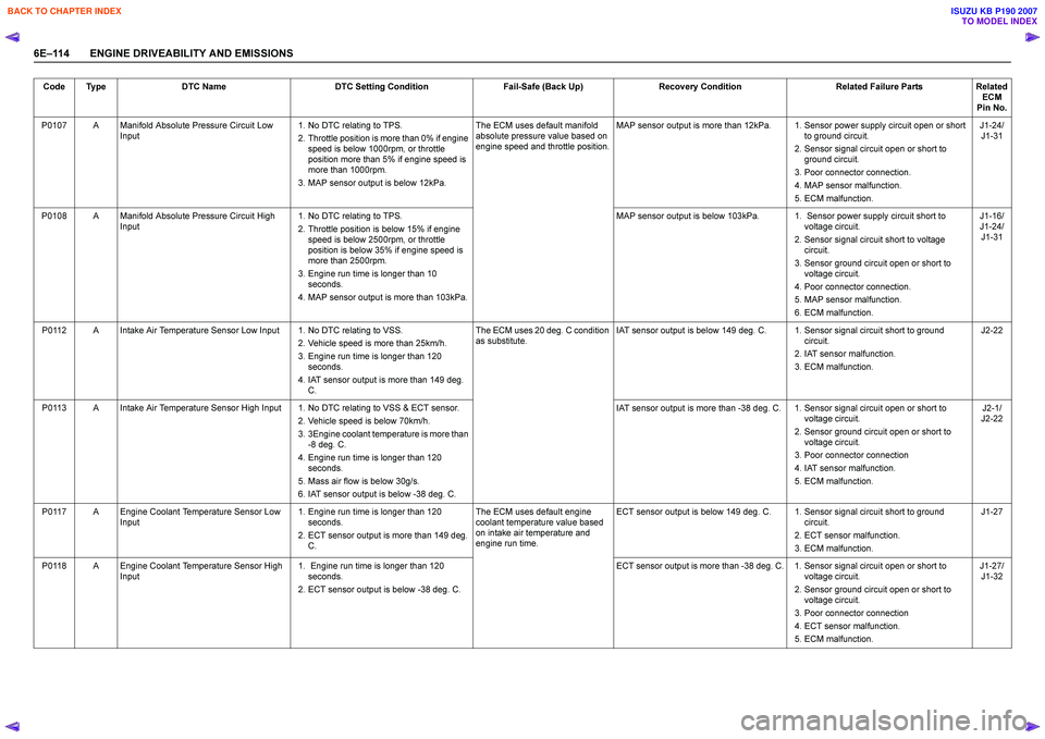
Code TypeDTC Name DTC Setting Condition Fail-Safe (Back Up)Recovery Condition Related Failure PartsRelated
ECM
Pin No.
P0107 A Manifold Absolute Pressure Circuit Low Input 1. No DTC relating to TPS.
2. Throttle position is more than 0% if engine speed is below 1000rpm, or throttle
position more than 5% if engine speed is
more than 1000rpm.
3. MAP sensor output is below 12kPa. The ECM uses default manifold
absolute pressure value based on
engine speed and throttle position. MAP sensor output is more than 12kPa. 1. Sensor power supply circuit open or short
to ground circuit.
2. Sensor signal circuit open or short to ground circuit.
3. Poor connector connection.
4. MAP sensor malfunction.
5. ECM malfunction. J1-24/
J1-31
P0108 A Manifold Absolute Pressure Circuit High Input 1. No DTC relating to TPS.
2. Throttle position is below 15% if engine speed is below 2500rpm, or throttle
position is below 35% if engine speed is
more than 2500rpm.
3. Engine run time is longer than 10 seconds.
4. MAP sensor output is more than 103kPa. MAP sensor output is below 103kPa. 1. Sensor power supply circuit short to
voltage circuit.
2. Sensor signal circuit short to voltage circuit.
3. Sensor ground circuit open or short to voltage circuit.
4. Poor connector connection.
5. MAP sensor malfunction.
6. ECM malfunction. J1-16/
J1-24/ J1-31
P0112 A Intake Air Temperature Sensor Low Input 1. No DTC relating to VSS. 2. Vehicle speed is more than 25km/h.
3. Engine run time is longer than 120 seconds.
4. IAT sensor output is more than 149 deg. C. The ECM uses 20 deg. C condition
as substitute. IAT sensor output is below 149 deg. C. 1. Sensor signal circuit short to ground
circuit.
2. IAT sensor malfunction.
3. ECM malfunction. J2-22
P0113 A Intake Air Temperature Sensor High Input 1. No DTC relating to VSS & ECT sensor. 2. Vehicle speed is below 70km/h.
3. 3Engine coolant temperature is more than -8 deg. C.
4. Engine run time is longer than 120 seconds.
5. Mass air flow is below 30g/s.
6. IAT sensor output is below -38 deg. C. IAT sensor output is more than -38 deg. C. 1. Sensor signal circuit open or short to
voltage circuit.
2. Sensor ground circuit open or short to voltage circuit.
3. Poor connector connection
4. IAT sensor malfunction.
5. ECM malfunction. J2-1/
J2-22
P0117 A Engine Coolant Temperature Sensor Low Input 1. Engine run time is longer than 120
seconds.
2. ECT sensor output is more than 149 deg. C. The ECM uses default engine
coolant temperature value based
on intake air temperature and
engine run time. ECT sensor output is below 149 deg. C. 1. Sensor signal circuit short to ground
circuit.
2. ECT sensor malfunction.
3. ECM malfunction. J1-27
P0118 A Engine Coolant Temperature Sensor High Input 1. Engine run time is longer than 120
seconds.
2. ECT sensor output is below -38 deg. C. ECT sensor output is more than -38 deg. C. 1. Sensor signal circuit open or short to
voltage circuit.
2. Sensor ground circuit open or short to voltage circuit.
3. Poor connector connection
4. ECT sensor malfunction.
5. ECM malfunction. J1-27/
J1-32
BACK TO CHAPTER INDEX
TO MODEL INDEX
ISUZU KB P190 2007
Page 2285 of 6020
ENGINE DRIVEABILITY AND EMISSIONS 6E–11 5
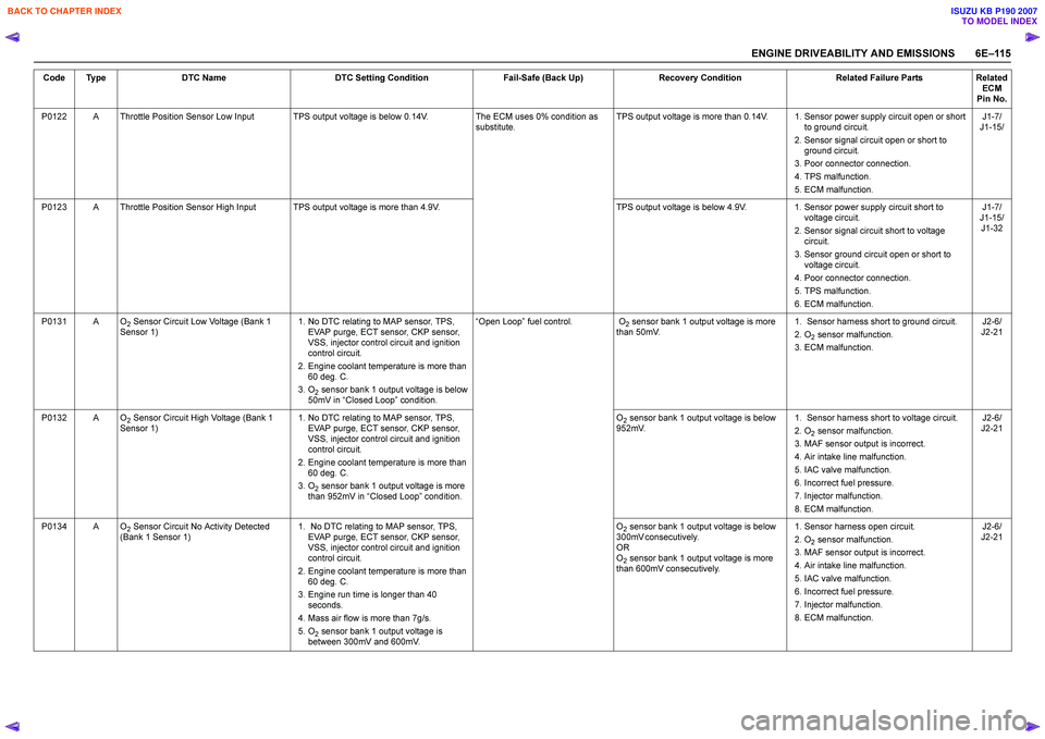
P0122 A Throttle Position Sensor Low Input TPS output voltage is below 0.14V. The ECM uses 0% condition as
substitute. TPS output voltage is more than 0.14V. 1. Sensor power supply circuit open or short
to ground circuit.
2. Sensor signal circuit open or short to ground circuit.
3. Poor connector connection.
4. TPS malfunction.
5. ECM malfunction. J1-7/
J1-15/
P0123 A Throttle Position Sensor High Input TPS output voltage is more than 4.9V. TPS output voltage is below 4.9V.1. Sensor power supply circuit short to
voltage circuit.
2. Sensor signal circuit short to voltage circuit.
3. Sensor ground circuit open or short to voltage circuit.
4. Poor connector connection.
5. TPS malfunction.
6. ECM malfunction. J1-7/
J1-15/ J1-32
P0131 A O
2 Sensor Circuit Low Voltage (Bank 1
Sensor 1) 1. No DTC relating to MAP sensor, TPS,
EVAP purge, ECT sensor, CKP sensor,
VSS, injector control circuit and ignition
control circuit.
2. Engine coolant temperature is more than 60 deg. C.
3. O
2 sensor bank 1 output voltage is below
50mV in “Closed Loop” condition. “Open Loop” fuel control. O
2 sensor bank 1 output voltage is more
than 50mV. 1. Sensor harness short to ground circuit.
2. O
2 sensor malfunction.
3. ECM malfunction. J2-6/
J2-21
P0132 A O
2 Sensor Circuit High Voltage (Bank 1
Sensor 1) 1. No DTC relating to MAP sensor, TPS,
EVAP purge, ECT sensor, CKP sensor,
VSS, injector control circuit and ignition
control circuit.
2. Engine coolant temperature is more than 60 deg. C.
3. O
2 sensor bank 1 output voltage is more
than 952mV in “Closed Loop” condition. O
2 sensor bank 1 output voltage is below
952mV. 1. Sensor harness short to voltage circuit.
2. O
2 sensor malfunction.
3. MAF sensor output is incorrect.
4. Air intake line malfunction.
5. IAC valve malfunction.
6. Incorrect fuel pressure.
7. Injector malfunction.
8. ECM malfunction. J2-6/
J2-21
P0134 A O
2 Sensor Circuit No Activity Detected
(Bank 1 Sensor 1) 1. No DTC relating to MAP sensor, TPS,
EVAP purge, ECT sensor, CKP sensor,
VSS, injector control circuit and ignition
control circuit.
2. Engine coolant temperature is more than 60 deg. C.
3. Engine run time is longer than 40 seconds.
4. Mass air flow is more than 7g/s.
5. O
2 sensor bank 1 output voltage is
between 300mV and 600mV. O
2 sensor bank 1 output voltage is below
3 0 0 m V c o n s e c u t i v e l y .
O R
O2 sensor bank 1 output voltage is more
than 600mV consecutively. 1. Sensor harness open circuit.
2. O
2 sensor malfunction.
3. MAF sensor output is incorrect.
4. Air intake line malfunction.
5. IAC valve malfunction.
6. Incorrect fuel pressure.
7. Injector malfunction.
8. ECM malfunction. J2-6/
J2-21
Code Type
DTC Name DTC Setting Condition Fail-Safe (Back Up)Recovery Condition Related Failure PartsRelated
ECM
Pin No.
BACK TO CHAPTER INDEX
TO MODEL INDEX
ISUZU KB P190 2007
Page 2286 of 6020
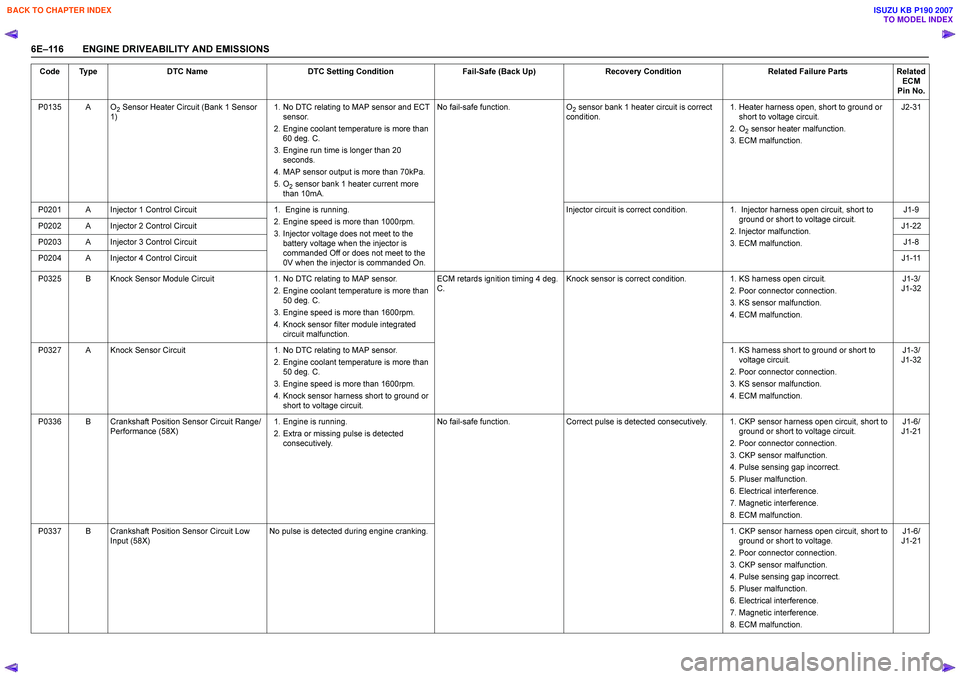
6E–116 ENGINE DRIVEABILITY AND EMISSIONSP0135 A O
2 Sensor Heater Circuit (Bank 1 Sensor
1) 1. No DTC relating to MAP sensor and ECT
sensor.
2. Engine coolant temperature is more than 60 deg. C.
3. Engine run time is longer than 20 seconds.
4. MAP sensor output is more than 70kPa.
5. O
2 sensor bank 1 heater current more
than 10mA. No fail-safe function.
O
2 sensor bank 1 heater circuit is correct
condition. 1. Heater harness open, short to ground or
short to voltage circuit.
2. O
2 sensor heater malfunction.
3. ECM malfunction. J2-31
P0201 A Injector 1 Control Circuit 1. Engine is running. 2. Engine speed is more than 1000rpm.
3. Injector voltage does not meet to the battery voltage when the injector is
commanded Off or does not meet to the
0V when the injector is commanded On. Injector circuit is correct condition.
1. Injector harness open circuit, short to
ground or short to voltage circuit.
2. Injector malfunction.
3. ECM malfunction. J1-9
P0202 A Injector 2 Control Circuit J1-22
P0203 A Injector 3 Control Circuit J1-8
P0204 A Injector 4 Control Circuit J1-11
P0325 B Knock Sensor Module Circuit 1. No DTC relating to MAP sensor.
2. Engine coolant temperature is more than 50 deg. C.
3. Engine speed is more than 1600rpm.
4. Knock sensor filter module integrated circuit malfunction. ECM retards ignition timing 4 deg.
C . Knock sensor is correct condition.
1. KS harness open circuit.
2. Poor connector connection.
3. KS sensor malfunction.
4. ECM malfunction. J1-3/
J1-32
P0327 A Knock Sensor Circuit 1. No DTC relating to MAP sensor.
2. Engine coolant temperature is more than 50 deg. C.
3. Engine speed is more than 1600rpm.
4. Knock sensor harness short to ground or short to voltage circuit. 1. KS harness short to ground or short to
voltage circuit.
2. Poor connector connection.
3. KS sensor malfunction.
4. ECM malfunction. J1-3/
J1-32
P0336 B Crankshaft Position Sensor Circuit Range/ Performance (58X) 1. Engine is running.
2. Extra or missing pulse is detected consecutively. No fail-safe function.
Correct pulse is detected consecutively. 1. CKP sensor harness open circuit, short to
ground or short to voltage circuit.
2. Poor connector connection.
3. CKP sensor malfunction.
4. Pulse sensing gap incorrect.
5. Pluser malfunction.
6. Electrical interference.
7. Magnetic interference.
8. ECM malfunction. J1-6/
J1-21
P0337 B Crankshaft Position Sensor Circuit Low Input (58X) No pulse is detected during engine cranking.
1. CKP sensor harness open circuit, short to
ground or short to voltage.
2. Poor connector connection.
3. CKP sensor malfunction.
4. Pulse sensing gap incorrect.
5. Pluser malfunction.
6. Electrical interference.
7. Magnetic interference.
8. ECM malfunction. J1-6/
J1-21
Code Type
DTC Name DTC Setting Condition Fail-Safe (Back Up)Recovery Condition Related Failure PartsRelated
ECM
Pin No.
BACK TO CHAPTER INDEX
TO MODEL INDEX
ISUZU KB P190 2007
Page 2287 of 6020
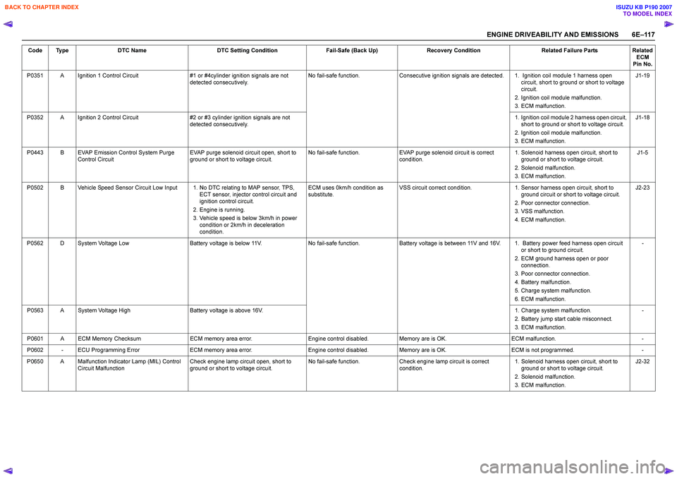
ENGINE DRIVEABILITY AND EMISSIONS 6E–11 7
P0351 A Ignition 1 Control Circuit #1 or #4cylinder ignition signals are not
detected consecutively. No fail-safe function.
Consecutive ignition signals are detected. 1. Ignition coil module 1 harness open
circuit, short to ground or short to voltage
circuit.
2. Ignition coil module malfunction.
3. ECM malfunction. J1-19
P0352 A Ignition 2 Control Circuit #2 or #3 cylinder ignition signals are not
detected consecutively. 1. Ignition coil module 2 harness open circuit,
short to ground or short to voltage circuit.
2. Ignition coil module malfunction.
3. ECM malfunction. J1-18
P0443 B EVAP Emission Control System Purge Control Circuit EVAP purge solenoid circuit open, short to
ground or short to voltage circuit. No fail-safe function.
EVAP purge solenoid circuit is correct
condition. 1. Solenoid harness open circuit, short to
ground or short to voltage circuit.
2. Solenoid malfunction.
3. ECM malfunction. J1-5
P0502 B Vehicle Speed Sensor Circuit Low Input 1. No DTC relating to MAP sensor, TPS, ECT sensor, injector control circuit and
ignition control circuit.
2. Engine is running.
3. Vehicle speed is below 3km/h in power condition or 2km/h in deceleration
condition. ECM uses 0km/h condition as
substitute. VSS circuit correct condition.
1. Sensor harness open circuit, short to
ground circuit or short to voltage circuit.
2. Poor connector connection.
3. VSS malfunction.
4. ECM malfunction. J2-23
P0562 D System Voltage Low Battery voltage is below 11V.No fail-safe function.Battery voltage is between 11V and 16V. 1. Battery power feed harness open circuit
or short to ground circuit.
2. ECM ground harness open or poor connection.
3. Poor connector connection.
4. Battery malfunction.
5. Charge system malfunction.
6. ECM malfunction. -
P0563 A System Voltage High Battery voltage is above 16V. 1. Charge system malfunction.
2. Battery jump start cable misconnect.
3. ECM malfunction. -
P0601 A ECM Memory Checksum ECM memory area error.Engine control disabled.Memory are is OK. ECM malfunction. -
P0602 - ECU Programming Error ECM memory area error.Engine control disabled.Memory are is OK. ECM is not programmed. -
P0650 A Malfunction Indicator Lamp (MIL) Control Circuit Malfunction Check engine lamp circuit open, short to
ground or short to voltage circuit. No fail-safe function.
Check engine lamp circuit is correct
condition. 1. Solenoid harness open circuit, short to
ground or short to voltage circuit.
2. Solenoid malfunction.
3. ECM malfunction. J2-32
Code Type
DTC Name DTC Setting Condition Fail-Safe (Back Up)Recovery Condition Related Failure PartsRelated
ECM
Pin No.
BACK TO CHAPTER INDEX
TO MODEL INDEX
ISUZU KB P190 2007
Page 2288 of 6020
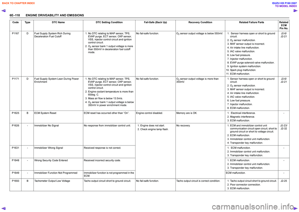
6E–118 ENGINE DRIVEABILITY AND EMISSIONSP1167 D Fuel Supply System Rich During
Deceleration Fuel Cutoff 1. No DTC relating to MAP sensor, TPS,
EVAP purge, ECT sensor, CKP sensor,
VSS, injector control circuit and ignition
control circuit.
2. O
2 sensor bank 1 output voltage is more
than 550mV in deceleration fuel cutoff
mode. No fail-safe function.
O
2 sensor output voltage is below 550mV. 1. Sensor harness open or short to ground
circuit.
2. O
2 sensor malfunction.
3. MAF sensor output is incorrect.
4. Air intake line malfunction.
5. IAC valve malfunction.
6. Low fuel pressure.
7. Injector malfunction.
8. EVAP purge solenoid valve malfunction.
9. Ignition system malfunction.
10. Spark plug malfunction. 11. ECM malfunction. J2-6/
J2-21
P1171 D Fuel Supply System Lean During Power Enrichment 1. No DTC relating to MAP sensor, TPS,
EVAP purge, ECT sensor, CKP sensor,
VSS, injector control circuit and ignition
control circuit.
2. Engine coolant temperature is more than 60deg. C.
3. Mass air flow is below 13.5m/s.
4. O
2 sensor bank 1 output voltage is below
350mV in power enrichment mode. No fail-safe function.
O
2 sensor output voltage is more than
350mV. 1. Sensor harness open or short to ground
circuit.
2. O
2 sensor malfunction.
3. MAF sensor output is incorrect.
4. Air intake line malfunction.
5. IAC valve malfunction.
6. Low fuel pressure.
7. Injector malfunction.
8. ECM malfunction. J2-6/
J2-21
P1625 B ECM System Reset ECM reset has occurred other than “On ”. Engine control disabled. Memory are is OK. 1. Electrical interference.
2. Magnetic interference.
3. ECM malfunction. -
P1626 - Immobilizer No Signal No response from immobilizer control unit. 1. Engine does not start.
2. Check engine lamp flash.No recovery.
1. ECM and immobilizer control unit
communication circuit open circuit, short to
ground circuit or short to voltage circuit.
2. ECM malfunction.
3. Immobilizer control unit malfunction.
4. Transponder key malfunction. J2-23/
J2-32
P1631 - Immobilizer Wrong Signal Received response is not correct. 1. ECM malfunction.
2. Immobilizer control unit malfunction.
3. Transponder key malfunction. -
P1648 - Wrong Security Code Entered Received incorrect security code. 1. ECM malfunction.
2. Immobilizer control unit malfunction.
3. Transponder key malfunction. -
P1649 - Immobilizer Function Not Programmed Immobilizer function is not programmed in the ECM. ECM malfunction.
-
P1693 B Tachometer Output Low Voltage Tacho output circuit short to ground circuit. No fail-safe function. Tacho output circuit is correct condition. 1. Tacho output circuit short to ground circuit.
2. Poor connector connection.
3. ECM malfunction. J2-25
Code Type
DTC Name DTC Setting Condition Fail-Safe (Back Up)Recovery Condition Related Failure PartsRelated
ECM
Pin No.
BACK TO CHAPTER INDEX
TO MODEL INDEX
ISUZU KB P190 2007
Page 2289 of 6020
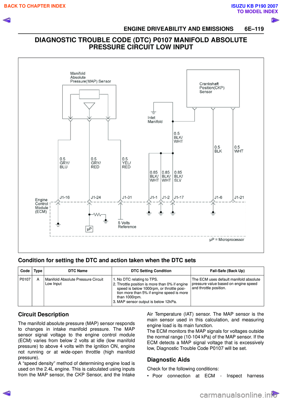
ENGINE DRIVEABILITY AND EMISSIONS 6E–119
DIAGNOSTIC TROUBLE CODE (DTC) P0107 MANIFOLD ABSOLUTE PRESSURE CIRCUIT LOW INPUT
Condition for setting the DTC and action taken when the DTC sets
Circuit Description
The manifold absolute pressure (MAP) sensor responds
to changes in intake manifold pressure. The MAP
sensor signal voltage to the engine control module
(ECM) varies from below 2 volts at idle (low manifold
pressure) to above 4 volts with the ignition ON, engine
not running or at wide-open throttle (high manifold
pressure).
A “speed density” method of determining engine load is
used on the 2.4L engine. This is calculated using inputs
from the MAP sensor, the CKP Sensor, and the Intake Air Temperature (IAT) sensor. The MAP sensor is the
main sensor used in this calculation, and measuring
engine load is its main function.
The ECM monitors the MAP signals for voltages outside
the normal range (10-104 kPa) of the MAP sensor. If the
ECM detects a MAP signal voltage that is excessively
low, Diagnostic Trouble Code P0107 will be set.
Diagnostic Aids
Check for the following conditions:
• Poor connection at ECM - Inspect harness
Code Type DTC Name DTC Setting Condition Fail-Safe (Back Up)
P0107 A Manifold Absolute Pressure Circuit Low Input 1. No DTC relating to TPS.
2. Throttle position is more than 0% if engine speed is below 1000rpm, or throttle posi-
tion more than 5% if engine speed is more
than 1000rpm.
3. MAP sensor output is below 12kPa. The ECM uses default manifold absolute
pressure value based on engine speed
and throttle position.
BACK TO CHAPTER INDEX
TO MODEL INDEX
ISUZU KB P190 2007