2007 ISUZU KB P190 engine
[x] Cancel search: enginePage 1228 of 6020

6E-194 Engine Control System (4JH1)
Step Action Value(s) Yes No
6 Observe the DTC Information with the scan tool.
Are there any DTCs that you have not diagnosed? Go to Diagnostic
Trouble Code (DTC) List System OK
BACK TO CHAPTER INDEX
TO MODEL INDEX
ISUZU KB P190 2007
Page 1229 of 6020
Engine Control System (4JH1) 6E-195
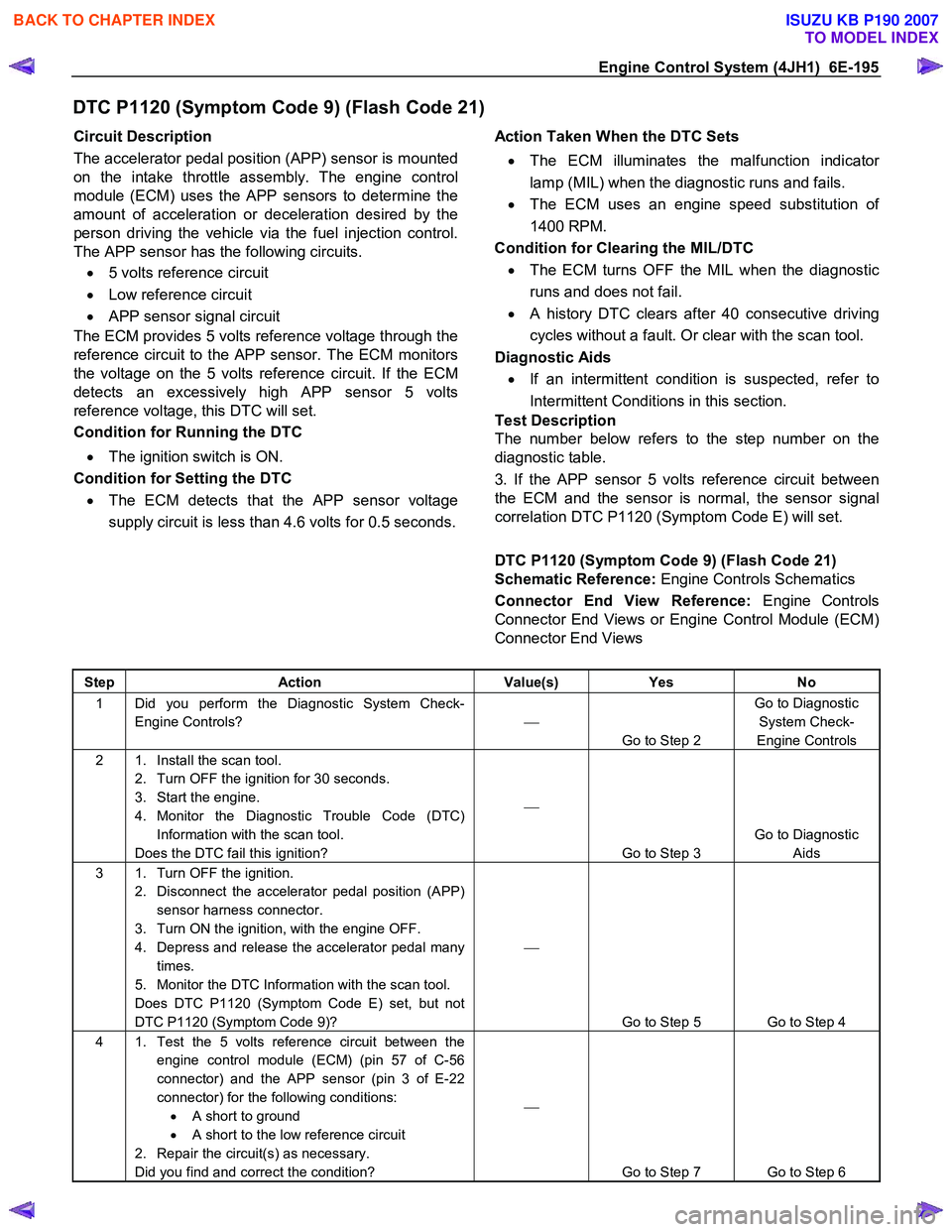
DTC P1120 (Symptom Code 9) (Flash Code 21)
Circuit Description
The accelerator pedal position (APP) sensor is mounted
on the intake throttle assembly. The engine control
module (ECM) uses the APP sensors to determine the
amount of acceleration or deceleration desired by the
person driving the vehicle via the fuel injection control.
The APP sensor has the following circuits.
• 5 volts reference circuit
• Low reference circuit
• APP sensor signal circuit
The ECM provides 5 volts reference voltage through the
reference circuit to the APP sensor. The ECM monitors
the voltage on the 5 volts reference circuit. If the ECM
detects an excessively high APP sensor 5 volts
reference voltage, this DTC will set.
Condition for Running the DTC
• The ignition switch is ON.
Condition for Setting the DTC
• The ECM detects that the APP sensor voltage
supply circuit is less than 4.6 volts for 0.5 seconds.
Action Taken When the DTC Sets
• The ECM illuminates the malfunction indicato
r
lamp (MIL) when the diagnostic runs and fails.
• The ECM uses an engine speed substitution o
f
1400 RPM.
Condition for Clearing the MIL/DTC • The ECM turns OFF the MIL when the diagnostic
runs and does not fail.
• A history DTC clears after 40 consecutive driving
cycles without a fault. Or clear with the scan tool.
Diagnostic Aids • If an intermittent condition is suspected, refer to
Intermittent Conditions in this section.
Test Description
The number below refers to the step number on the
diagnostic table.
3. If the APP sensor 5 volts reference circuit between
the ECM and the sensor is normal, the sensor signal
correlation DTC P1120 (Symptom Code E) will set.
DTC P1120 (Symptom Code 9) (Flash Code 21)
Schematic Reference: Engine Controls Schematics
Connector End View Reference: Engine Controls
Connector End Views or Engine Control Module (ECM)
Connector End Views
Step Action Value(s) Yes No
1 Did you perform the Diagnostic System Check-
Engine Controls?
Go to Step 2 Go to Diagnostic
System Check-
Engine Controls
2 1. Install the scan tool. 2. Turn OFF the ignition for 30 seconds.
3. Start the engine.
4. Monitor the Diagnostic Trouble Code (DTC) Information with the scan tool.
Does the DTC fail this ignition?
Go to Step 3 Go to Diagnostic
Aids
3 1. Turn OFF the ignition. 2. Disconnect the accelerator pedal position (APP) sensor harness connector.
3. Turn ON the ignition, with the engine OFF.
4. Depress and release the accelerator pedal many times.
5. Monitor the DTC Information with the scan tool.
Does DTC P1120 (Symptom Code E) set, but not
DTC P1120 (Symptom Code 9)?
Go to Step 5 Go to Step 4
4 1. Test the 5 volts reference circuit between the engine control module (ECM) (pin 57 of C-56
connector) and the APP sensor (pin 3 of E-22
connector) for the following conditions: • A short to ground
• A short to the low reference circuit
2. Repair the circuit(s) as necessary.
Did you find and correct the condition?
Go to Step 7 Go to Step 6
BACK TO CHAPTER INDEX
TO MODEL INDEX
ISUZU KB P190 2007
Page 1230 of 6020
6E-196 Engine Control System (4JH1)
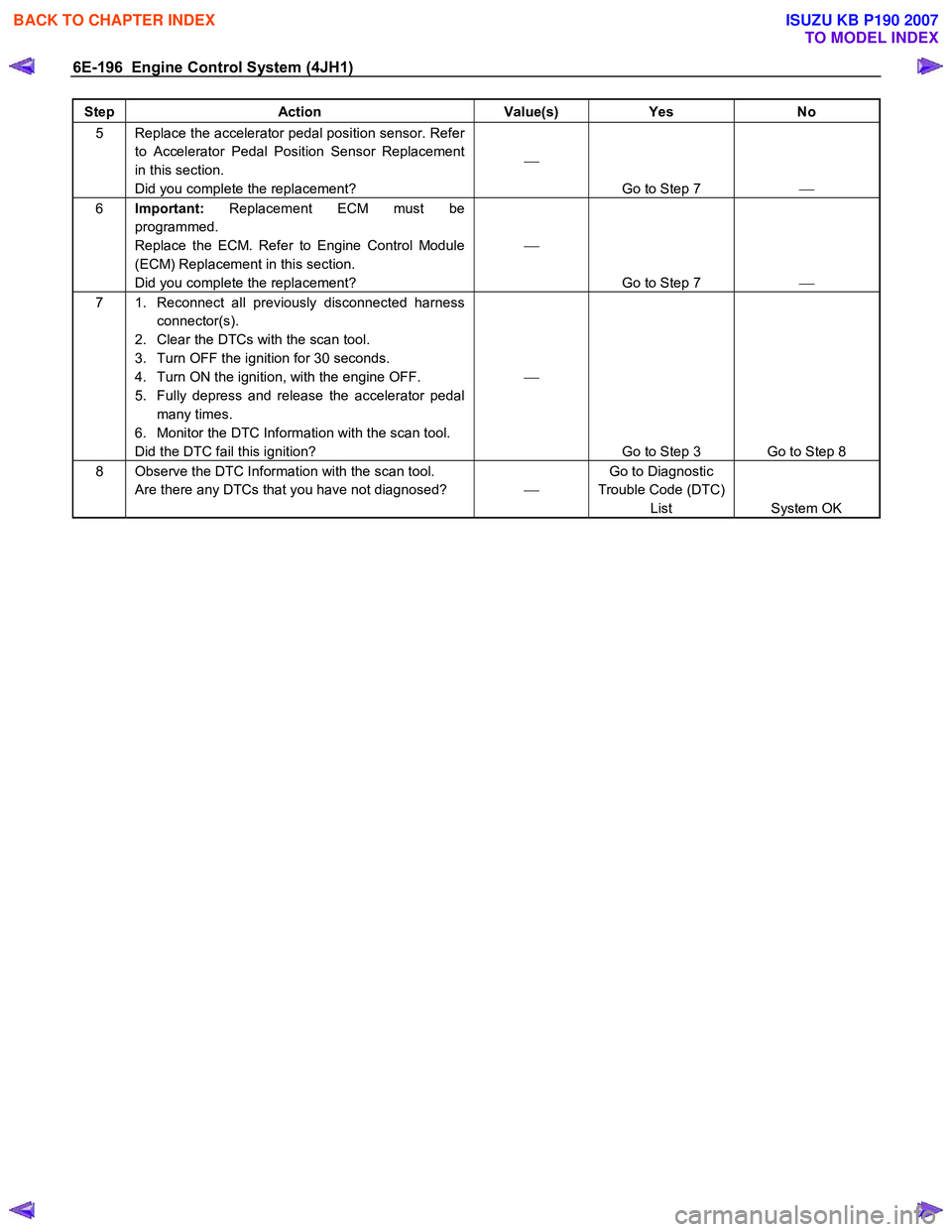
Step Action Value(s) Yes No
5 Replace the accelerator pedal position sensor. Refer
to Accelerator Pedal Position Sensor Replacement
in this section.
Did you complete the replacement?
Go to Step 7
6 Important: Replacement ECM must be
programmed.
Replace the ECM. Refer to Engine Control Module
(ECM) Replacement in this section.
Did you complete the replacement?
Go to Step 7
7 1. Reconnect all previously disconnected harness
connector(s).
2. Clear the DTCs with the scan tool.
3. Turn OFF the ignition for 30 seconds.
4. Turn ON the ignition, with the engine OFF.
5. Fully depress and release the accelerator pedal many times.
6. Monitor the DTC Information with the scan tool.
Did the DTC fail this ignition?
Go to Step 3 Go to Step 8
8 Observe the DTC Information with the scan tool. Are there any DTCs that you have not diagnosed? Go to Diagnostic
Trouble Code (DTC) List System OK
BACK TO CHAPTER INDEX
TO MODEL INDEX
ISUZU KB P190 2007
Page 1231 of 6020
Engine Control System (4JH1) 6E-197
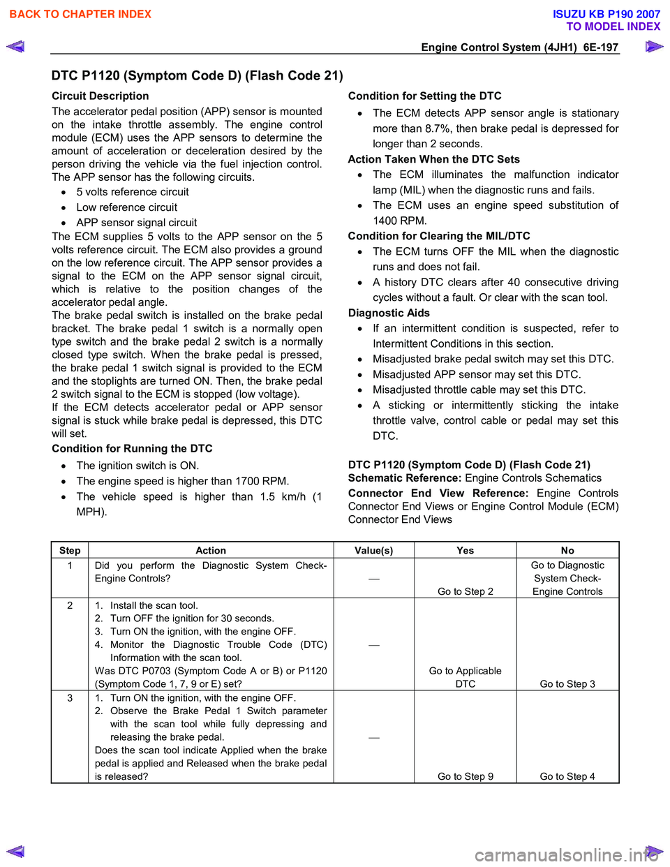
DTC P1120 (Symptom Code D) (Flash Code 21)
Circuit Description
The accelerator pedal position (APP) sensor is mounted
on the intake throttle assembly. The engine control
module (ECM) uses the APP sensors to determine the
amount of acceleration or deceleration desired by the
person driving the vehicle via the fuel injection control.
The APP sensor has the following circuits.
• 5 volts reference circuit
• Low reference circuit
• APP sensor signal circuit
The ECM supplies 5 volts to the APP sensor on the 5
volts reference circuit. The ECM also provides a ground
on the low reference circuit. The APP sensor provides a
signal to the ECM on the APP sensor signal circuit,
which is relative to the position changes of the
accelerator pedal angle.
The brake pedal switch is installed on the brake pedal
bracket. The brake pedal 1 switch is a normally open
type switch and the brake pedal 2 switch is a normally
closed type switch. W hen the brake pedal is pressed,
the brake pedal 1 switch signal is provided to the ECM
and the stoplights are turned ON. Then, the brake pedal
2 switch signal to the ECM is stopped (low voltage).
If the ECM detects accelerator pedal or APP senso
r
signal is stuck while brake pedal is depressed, this DTC
will set.
Condition for Running the DTC
• The ignition switch is ON.
• The engine speed is higher than 1700 RPM.
• The vehicle speed is higher than 1.5 km/h (1
MPH).
Condition for Setting the DTC
• The ECM detects APP sensor angle is stationar
y
more than 8.7%, then brake pedal is depressed fo
r
longer than 2 seconds.
Action Taken When the DTC Sets • The ECM illuminates the malfunction indicato
r
lamp (MIL) when the diagnostic runs and fails.
• The ECM uses an engine speed substitution o
f
1400 RPM.
Condition for Clearing the MIL/DTC • The ECM turns OFF the MIL when the diagnostic
runs and does not fail.
• A history DTC clears after 40 consecutive driving
cycles without a fault. Or clear with the scan tool.
Diagnostic Aids • If an intermittent condition is suspected, refer to
Intermittent Conditions in this section.
• Misadjusted brake pedal switch may set this DTC.
• Misadjusted APP sensor may set this DTC.
• Misadjusted throttle cable may set this DTC.
• A sticking or intermittently sticking the intake
throttle valve, control cable or pedal may set this
DTC.
DTC P1120 (Symptom Code D) (Flash Code 21)
Schematic Reference: Engine Controls Schematics
Connector End View Reference: Engine Controls
Connector End Views or Engine Control Module (ECM)
Connector End Views
Step Action Value(s) Yes No
1 Did you perform the Diagnostic System Check-
Engine Controls?
Go to Step 2 Go to Diagnostic
System Check-
Engine Controls
2 1. Install the scan tool. 2. Turn OFF the ignition for 30 seconds.
3. Turn ON the ignition, with the engine OFF.
4. Monitor the Diagnostic Trouble Code (DTC) Information with the scan tool.
W as DTC P0703 (Symptom Code A or B) or P1120
(Symptom Code 1, 7, 9 or E) set?
Go to Applicable DTC Go to Step 3
3 1. Turn ON the ignition, with the engine OFF. 2. Observe the Brake Pedal 1 Switch parameter with the scan tool while fully depressing and
releasing the brake pedal.
Does the scan tool indicate Applied when the brake
pedal is applied and Released when the brake pedal
is released?
Go to Step 9 Go to Step 4
BACK TO CHAPTER INDEX
TO MODEL INDEX
ISUZU KB P190 2007
Page 1232 of 6020
6E-198 Engine Control System (4JH1)
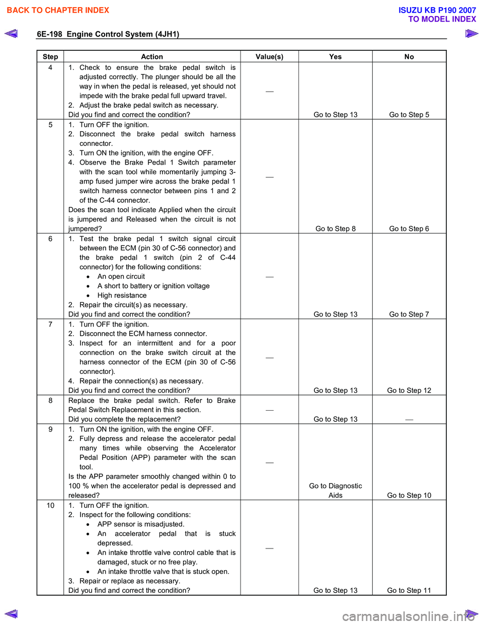
Step Action Value(s) Yes No
4 1. Check to ensure the brake pedal switch is
adjusted correctly. The plunger should be all the
way in when the pedal is released, yet should not
impede with the brake pedal full upward travel.
2. Adjust the brake pedal switch as necessary.
Did you find and correct the condition?
Go to Step 13 Go to Step 5
5 1. Turn OFF the ignition. 2. Disconnect the brake pedal switch harness connector.
3. Turn ON the ignition, with the engine OFF.
4. Observe the Brake Pedal 1 Switch parameter with the scan tool while momentarily jumping 3-
amp fused jumper wire across the brake pedal 1
switch harness connector between pins 1 and 2
of the C-44 connector.
Does the scan tool indicate Applied when the circuit
is jumpered and Released when the circuit is not
jumpered?
Go to Step 8 Go to Step 6
6 1. Test the brake pedal 1 switch signal circuit between the ECM (pin 30 of C-56 connector) and
the brake pedal 1 switch (pin 2 of C-44
connector) for the following conditions: • An open circuit
• A short to battery or ignition voltage
• High resistance
2. Repair the circuit(s) as necessary.
Did you find and correct the condition?
Go to Step 13 Go to Step 7
7 1. Turn OFF the ignition. 2. Disconnect the ECM harness connector.
3. Inspect for an intermittent and for a poor connection on the brake switch circuit at the
harness connector of the ECM (pin 30 of C-56
connector).
4. Repair the connection(s) as necessary.
Did you find and correct the condition?
Go to Step 13 Go to Step 12
8 Replace the brake pedal switch. Refer to Brake Pedal Switch Replacement in this section.
Did you complete the replacement?
Go to Step 13
9 1. Turn ON the ignition, with the engine OFF.
2. Fully depress and release the accelerator pedal many times while observing the Accelerator
Pedal Position (APP) parameter with the scan
tool.
Is the APP parameter smoothly changed within 0 to
100 % when the accelerator pedal is depressed and
released?
Go to Diagnostic Aids Go to Step 10
10 1. Turn OFF the ignition. 2. Inspect for the following conditions: • APP sensor is misadjusted.
• An accelerator pedal that is stuck
depressed.
• An intake throttle valve control cable that is
damaged, stuck or no free play.
• An intake throttle valve that is stuck open.
3. Repair or replace as necessary.
Did you find and correct the condition?
Go to Step 13 Go to Step 11
BACK TO CHAPTER INDEX
TO MODEL INDEX
ISUZU KB P190 2007
Page 1233 of 6020
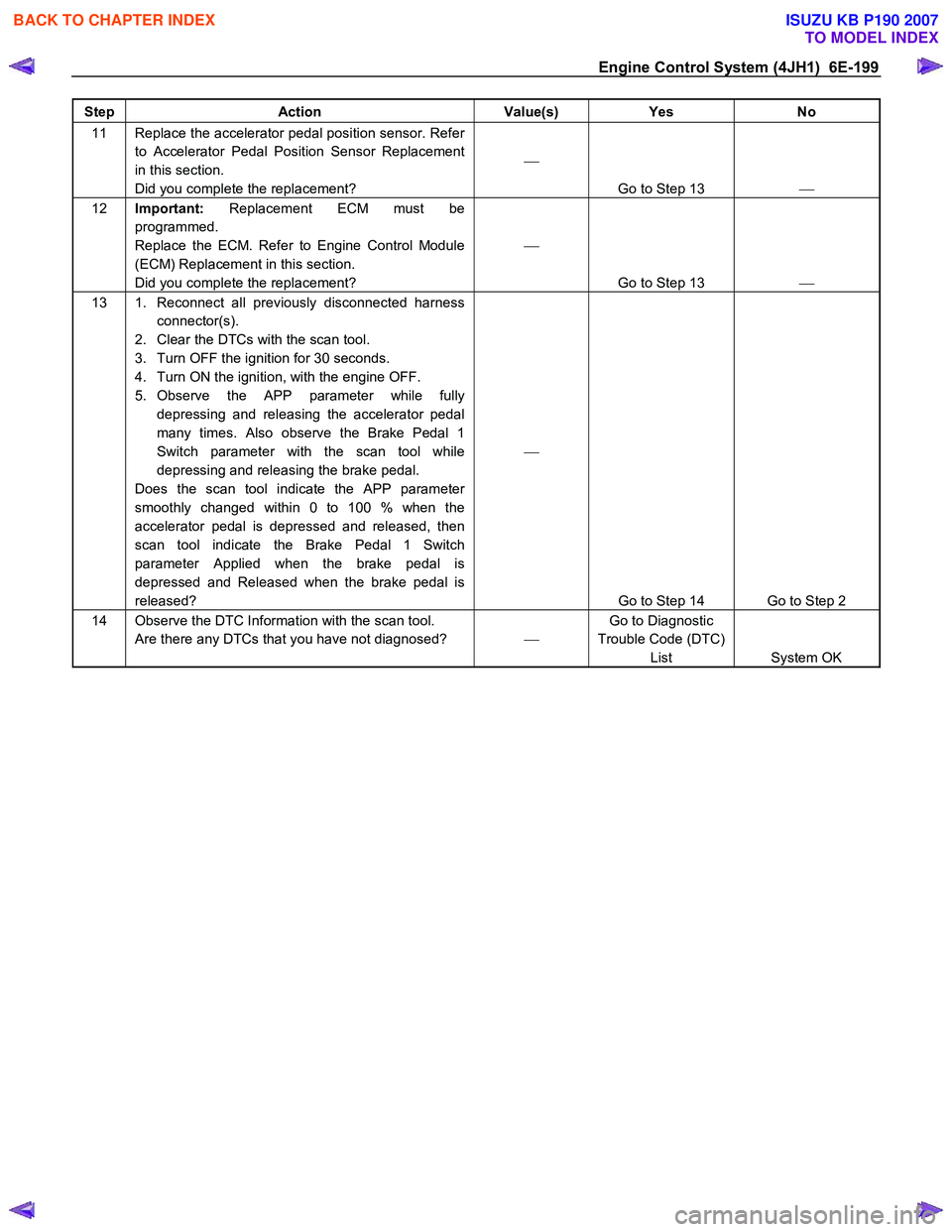
Engine Control System (4JH1) 6E-199
Step Action Value(s) Yes No
11 Replace the accelerator pedal position sensor. Refer
to Accelerator Pedal Position Sensor Replacement
in this section.
Did you complete the replacement?
Go to Step 13
12 Important: Replacement ECM must be
programmed.
Replace the ECM. Refer to Engine Control Module
(ECM) Replacement in this section.
Did you complete the replacement?
Go to Step 13
13 1. Reconnect all previously disconnected harness
connector(s).
2. Clear the DTCs with the scan tool.
3. Turn OFF the ignition for 30 seconds.
4. Turn ON the ignition, with the engine OFF.
5. Observe the APP parameter while fully depressing and releasing the accelerator pedal
many times. Also observe the Brake Pedal 1
Switch parameter with the scan tool while
depressing and releasing the brake pedal.
Does the scan tool indicate the APP parameter
smoothly changed within 0 to 100 % when the
accelerator pedal is depressed and released, then
scan tool indicate the Brake Pedal 1 Switch
parameter Applied when the brake pedal is
depressed and Released when the brake pedal is
released?
Go to Step 14 Go to Step 2
14 Observe the DTC Information with the scan tool. Are there any DTCs that you have not diagnosed? Go to Diagnostic
Trouble Code (DTC) List System OK
BACK TO CHAPTER INDEX
TO MODEL INDEX
ISUZU KB P190 2007
Page 1234 of 6020
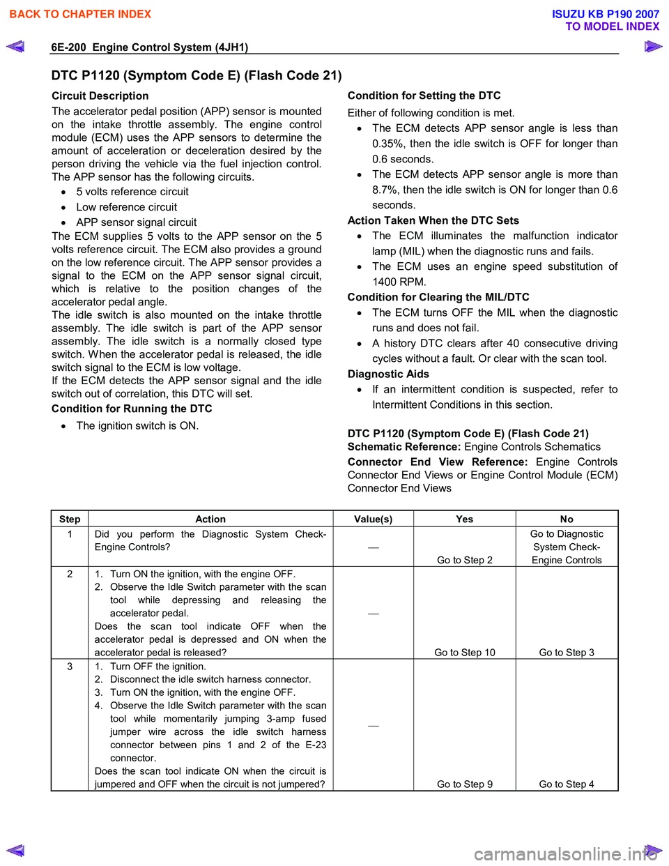
6E-200 Engine Control System (4JH1)
DTC P1120 (Symptom Code E) (Flash Code 21)
Circuit Description
The accelerator pedal position (APP) sensor is mounted
on the intake throttle assembly. The engine control
module (ECM) uses the APP sensors to determine the
amount of acceleration or deceleration desired by the
person driving the vehicle via the fuel injection control.
The APP sensor has the following circuits.
• 5 volts reference circuit
• Low reference circuit
• APP sensor signal circuit
The ECM supplies 5 volts to the APP sensor on the 5
volts reference circuit. The ECM also provides a ground
on the low reference circuit. The APP sensor provides a
signal to the ECM on the APP sensor signal circuit,
which is relative to the position changes of the
accelerator pedal angle.
The idle switch is also mounted on the intake throttle
assembly. The idle switch is part of the APP senso
r
assembly. The idle switch is a normally closed type
switch. W hen the accelerator pedal is released, the idle
switch signal to the ECM is low voltage.
If the ECM detects the
APP sensor signal and the idle
switch out of correlation, this DTC will set.
Condition for Running the DTC
• The ignition switch is ON.
Condition for Setting the DTC
Either of following condition is met. • The ECM detects APP sensor angle is less than
0.35%, then the idle switch is OFF for longer than
0.6 seconds.
• The ECM detects APP sensor angle is more than
8.7%, then the idle switch is ON for longer than 0.6
seconds.
Action Taken When the DTC Sets • The ECM illuminates the malfunction indicato
r
lamp (MIL) when the diagnostic runs and fails.
• The ECM uses an engine speed substitution o
f
1400 RPM.
Condition for Clearing the MIL/DTC • The ECM turns OFF the MIL when the diagnostic
runs and does not fail.
• A history DTC clears after 40 consecutive driving
cycles without a fault. Or clear with the scan tool.
Diagnostic Aids • If an intermittent condition is suspected, refer to
Intermittent Conditions in this section.
DTC P1120 (Symptom Code E) (Flash Code 21)
Schematic Reference: Engine Controls Schematics
Connector End View Reference: Engine Controls
Connector End Views or Engine Control Module (ECM)
Connector End Views
Step Action Value(s) Yes No
1 Did you perform the Diagnostic System Check-
Engine Controls?
Go to Step 2 Go to Diagnostic
System Check-
Engine Controls
2 1. Turn ON the ignition, with the engine OFF. 2. Observe the Idle Switch parameter with the scan tool while depressing and releasing the
accelerator pedal.
Does the scan tool indicate OFF when the
accelerator pedal is depressed and ON when the
accelerator pedal is released?
Go to Step 10 Go to Step 3
3 1. Turn OFF the ignition. 2. Disconnect the idle switch harness connector.
3. Turn ON the ignition, with the engine OFF.
4. Observe the Idle Switch parameter with the scan tool while momentarily jumping 3-amp fused
jumper wire across the idle switch harness
connector between pins 1 and 2 of the E-23
connector.
Does the scan tool indicate ON when the circuit is
jumpered and OFF when the circuit is not jumpered?
Go to Step 9 Go to Step 4
BACK TO CHAPTER INDEX
TO MODEL INDEX
ISUZU KB P190 2007
Page 1235 of 6020
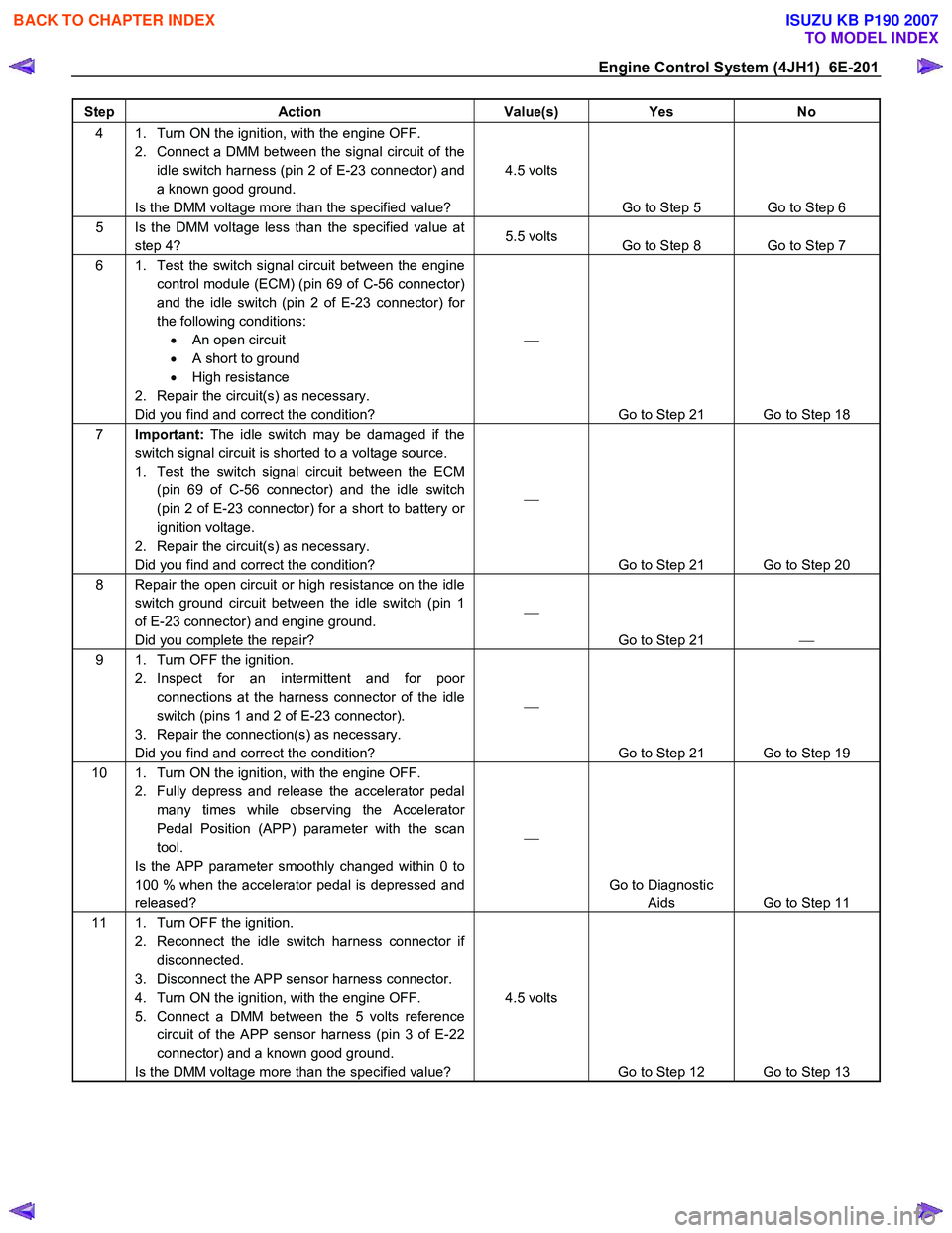
Engine Control System (4JH1) 6E-201
Step Action Value(s) Yes No
4 1. Turn ON the ignition, with the engine OFF.
2. Connect a DMM between the signal circuit of the idle switch harness (pin 2 of E-23 connector) and
a known good ground.
Is the DMM voltage more than the specified value? 4.5 volts
Go to Step 5 Go to Step 6
5 Is the DMM voltage less than the specified value at step 4? 5.5 volts
Go to Step 8 Go to Step 7
6 1. Test the switch signal circuit between the engine
control module (ECM) (pin 69 of C-56 connector)
and the idle switch (pin 2 of E-23 connector) for
the following conditions: • An open circuit
• A short to ground
• High resistance
2. Repair the circuit(s) as necessary.
Did you find and correct the condition?
Go to Step 21 Go to Step 18
7 Important: The idle switch may be damaged if the
switch signal circuit is shorted to a voltage source.
1. Test the switch signal circuit between the ECM (pin 69 of C-56 connector) and the idle switch
(pin 2 of E-23 connector) for a short to battery or
ignition voltage.
2. Repair the circuit(s) as necessary.
Did you find and correct the condition?
Go to Step 21 Go to Step 20
8 Repair the open circuit or high resistance on the idle switch ground circuit between the idle switch (pin 1
of E-23 connector) and engine ground.
Did you complete the repair?
Go to Step 21
9 1. Turn OFF the ignition.
2. Inspect for an intermittent and for poor connections at the harness connector of the idle
switch (pins 1 and 2 of E-23 connector).
3. Repair the connection(s) as necessary.
Did you find and correct the condition?
Go to Step 21 Go to Step 19
10 1. Turn ON the ignition, with the engine OFF. 2. Fully depress and release the accelerator pedal many times while observing the Accelerator
Pedal Position (APP) parameter with the scan
tool.
Is the APP parameter smoothly changed within 0 to
100 % when the accelerator pedal is depressed and
released?
Go to Diagnostic Aids Go to Step 11
11 1. Turn OFF the ignition.
2. Reconnect the idle switch harness connector if disconnected.
3. Disconnect the APP sensor harness connector.
4. Turn ON the ignition, with the engine OFF.
5. Connect a DMM between the 5 volts reference circuit of the APP sensor harness (pin 3 of E-22
connector) and a known good ground.
Is the DMM voltage more than the specified value? 4.5 volts
Go to Step 12 Go to Step 13
BACK TO CHAPTER INDEX
TO MODEL INDEX
ISUZU KB P190 2007