2007 ISUZU KB P190 window
[x] Cancel search: windowPage 5556 of 6020
8A-618 ELECTRICAL-BODY AND CHASSIS
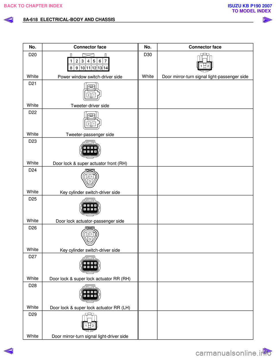
No. Connector face No. Connector face
D20
White
Power window switch-driver side D30
White
Door mirror-turn signal light-passenger side
D21
White
Tweeter-driver side
D22
White
Tweeter-passenger side
D23
White
Door lock & super actuator front (RH)
D24
White
Key cylinder switch-driver side
D25
White
Door lock actuator-passenger side
D26
White
Key cylinder switch-driver side
D27
White
Door lock & super lock actuator RR (RH)
D28
White
Door lock & super lock actuator RR (LH)
D29
White
Door mirror-turn signal light-driver side
BACK TO CHAPTER INDEX
TO MODEL INDEXISUZU KB P190 2007
Page 5665 of 6020
9A-30 SUPPLEMENTAL RESTRAINT SYSTEM
23. Verify that the inside of the vehicle and the area
surrounding the vehicle are clear of all people and
loose or flammable objects.
24. Stretch the driver and passenger deployment harnesses to their full length.
25. Completely cover the windshield area and front door window openings with a drop cloth, blanket o
r
similar item. This reduces the possibility of injury
due to possible fragmentation of the vehicle's
glass or interior.
26. Notify all people in the immediate area that you intend to deploy the air bags. The deployment will
be accompanied by a substantial noise which ma
y
startle the uninformed.
27. Separate the two ends of the driver deployment harness wires.
WARNING: DEPLOYMENT WIRES SHALL REMAIN
SHORTED AND NOT BE CONNECTED TO
A
POWER SOURCE UNTIL THE AIR BAG IS TO BE
DEPLOYED. THE AIR BAG ASSEMBLY WILL
IMMEDIATELY DEPLOY THE AIR BAG WHEN
A
POWER SOURCE IS CONNECTED TO IT.
CONNECTING THE DEPLOYMENT WIRES TO THE
POWER SOURCE SHOULD ALWAYS BE THE
FINAL STEP IN THE AIR BAG ASSEMBLY
DEPLOYMENT PROCEDURE. FAILURE TO
FOLLOW PROCEDURES IN THE ORDER LISTED
COULD RESULT IN PERSONAL INJURY.
NOTE: W hen the air bag deploys, the rapid gas
expansion will create a substantial noise. Notify all
people in the immediate area that you intend to deplo
y
the air bags.
28. Connect the driver deployment harness wires to a power source to immediately deploy the driver ai
r
bag assembly. Recommended application: 12
volts minimum, 2 amps minimum. A vehicle
battery is suggested.
29. Separate the two ends of the passenge
r
deployment harness wires.
WARNING: DEPLOYMENT WIRES SHALL REMAIN
SHORTED AND NOT BE CONNECTED TO
A
POWER SOURCE UNTIL THE AIR BAG IS TO BE
DEPLOYED. THE AIR BAG ASSEMBLY WILL
IMMEDIATELY DEPLOY THE AIR BAG WHEN
A
POWER SOURCE IS CONNECTED TO IT.
CONNECTING THE DEPLOYMENT WIRES TO THE
POWER SOURCE SHOULD ALWAYS BE THE
FINAL STEP IN THE AIR BAG ASSEMBLY
DEPLOYMENT PROCEDURE. FAILURE TO
FOLLOW PROCEDURES IN THE ORDER LISTED
COULD RESULT IN PERSONAL INJURY.
30. Connect the passenger deployment harness wires
to a power source to immediately deploy the
passenger air bag assembly. Recommended
application: 12 volts minimum, 2 amps minimum.
A vehicle battery is suggested.(Driver air bag
assembly) Put on a pair of shop gloves and safet
y
glasses to protect your hands and eyes from
possible irritation and heat when handling the
deployed air bag assembly. After an air bag
assembly has been deployed, the surface of the
air bag may contain a powdery residue. This
powder consists primarily of cornstarch (used to
lubricate the bag as it inflates) and by-products o
f
the chemical reaction. Sodium hydroxide dust
(similar to lye soap) is produced as a by-product o
f
the deployment reaction. The sodium hydroxide
then quickly reacts with atmospheric moisture and
is converted to sodium carbonate and sodium
bicarbonate (baking soda). Therefore, it is unlikel
y
that sodium hydroxide will be present afte
r
deployment (Passenger air bag assembly) The
passenger inflator requires no special precaution
after deployment. 95% of the particulate mission is
potassium chloride (KLC), which is commonly sold
as an edible salt-substitute. Even if water is
applied, post deployment products are relativel
y
pH neutral. Disposing of the inflator by burying it in
a landfill will not produce any hazardous products.
As with any dusty environment, safety goggles,
dust mask and gloves should be worn.
WARNING: SAFETY PRECAUTIONS MUST BE
OBSERVED WHEN HANDLING A DEPLOYED AIR
BAG ASSEMBLY. AFTER DEPLOYMENT, THE
METAL SURFACES OF THE AIR BAG ASSEMBLY
WILL BE VERY HOT. ALLOW THE AIR BAG
ASSEMBLY TO COOL BEFORE HANDLING ANY
METAL PORTION OF IT. DO NOT PLACE THE HOT
DEPLOYED AIR BAG ASSEMBLY NEAR ANY
FLAMMABLE OBJECTS. FAILURE TO FOLLOW
PROCEDURES COULD RESULT IN FIRE OR
PERSONAL INJURY.
After an air bag assembly has been deployed, the
metal canister and surrounding areas of the ai
r
bag assembly will be very hot. Do not touch the
metal areas of the air bag assembly for about 30
minutes after deployment. If the deployed air bag
assembly must be moved before it is cool, wea
r
gloves and handle by the air bag or trim cover.
31. Short the driver deployment harness wires b
y
twisting together one end from each. Repeat this
procedure for the passenger deployment harness.
32. Carefully remove the drop cloth from the vehicle and clean off any fragments or discard the drop
cloth entirely.
33. Disconnect the driver deployment harness and the passenger deployment harness from the vehicle
and discard.
BACK TO CHAPTER INDEX TO MODEL INDEXISUZU KB P190 2007
Page 5759 of 6020
CAB 10-1
SECTION 10
CAB
TABLE OF CONTENTS
PAGE
Windshield ..................................................................................................................... .... 10- 2
Rear Window Assembly .................................................................................................... 10- 6
Front Door Assembly ........................................................................................................ 10- 9
Rear Door Assembly (Crew Cab) ..................................................................................... 10- 19
Instrument Panel ............................................................................................................... 10- 27
Floor Console .................................................................................................................. .. 10- 35
Console Box (Without Floor Console) ............................................................................. 10- 39
Headlining ..................................................................................................................... ..... 10- 40
Interior Trim Panels ........................................................................................................... 10- 45
Fuel Filler Lid Opener Lever/Cable .................................................................................. 10- 56
Quarter Glass (Extend Cab).............................................................................................. 10- 71
Font Seat ...................................................................................................................... ...... 10- 72
Rear Seat (Crew Cab) ........................................................................................................ 10- 74
Jump Seat (Extend Cab) ................................................................................................... 10- 75
Front Seat Belt ................................................................................................................ ... 10- 76
Rear Seat Belt (Crew Cab) ................................................................................................ 10- 80
Rear Seat Belt (Extend Cab) ............................................................................................. 10- 84
Front Wheel Extension (A type) ....................................................................................... 10- 87
Front Wheel Extension (B type) ....................................................................................... 10- 88
Rear Wheel Extension (A type)......................................................................................... 10- 89
Rear Wheel Extension (B type)......................................................................................... 10- 90
Tail Gate Assembly ........................................................................................................... 10 - 91
TO MODEL INDEX
BACK TO MAIN INDEX
ISUZU KB P190 2007
Page 5764 of 6020
10-6 CAB
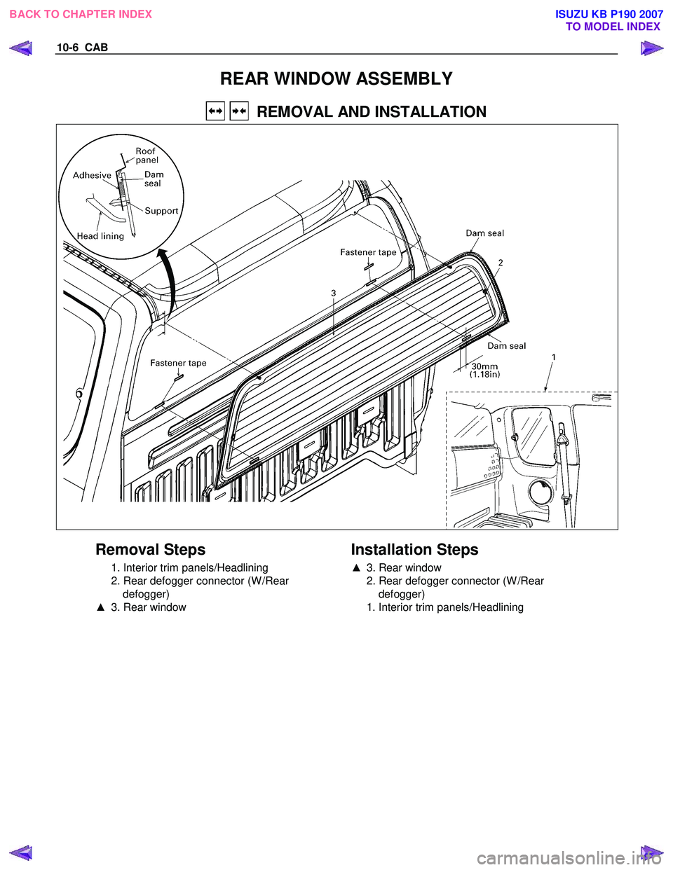
REAR WINDOW ASSEMBLY
REMOVAL AND INSTALLATION
Removal Steps
1. Interior trim panels/Headlining
2. Rear defogger connector (W /Rear defogger)
▲ 3. Rear window
Installation Steps
▲
3. Rear window
2. Rear defogger connector (W /Rear defogger)
1. Interior trim panels/Headlining
BACK TO CHAPTER INDEX TO MODEL INDEX
ISUZU KB P190 2007
Page 5765 of 6020
CAB 10-7
Important Operation - Removal
3. Rear Window
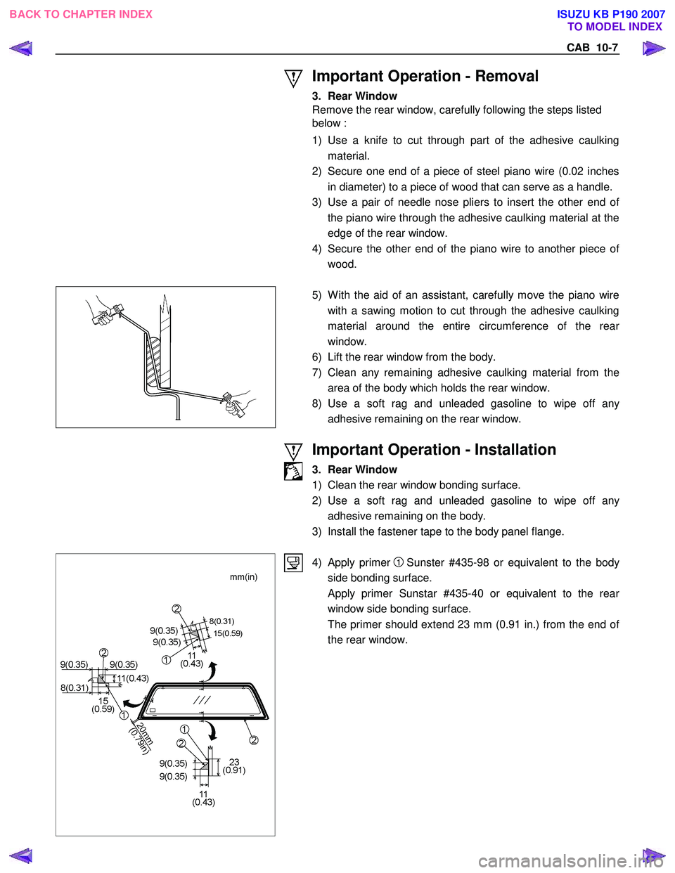
Remove the rear window, carefully following the steps listed
below :
1) Use a knife to cut through part of the adhesive caulking material.
2) Secure one end of a piece of steel piano wire (0.02 inches in diameter) to a piece of wood that can serve as a handle.
3) Use a pair of needle nose pliers to insert the other end o
f
the piano wire through the adhesive caulking material at the
edge of the rear window.
4) Secure the other end of the piano wire to another piece o
f
wood.
5) W ith the aid of an assistant, carefully move the piano wire
with a sawing motion to cut through the adhesive caulking
material around the entire circumference of the rea
r
window.
6) Lift the rear window from the body.
7) Clean any remaining adhesive caulking material from the area of the body which holds the rear window.
8) Use a soft rag and unleaded gasoline to wipe off an
y
adhesive remaining on the rear window.
Important Operation - Installation
3. Rear Window
1) Clean the rear window bonding surface.
2) Use a soft rag and unleaded gasoline to wipe off an
y
adhesive remaining on the body.
3) Install the fastener tape to the body panel flange.
4) Apply primer 1 Sunster #435-98 or equivalent to the body
side bonding surface.
Apply primer Sunstar #435-40 or equivalent to the rea
r
window side bonding surface.
The primer should extend 23 mm (0.91 in.) from the end o
f
the rear window.
BACK TO CHAPTER INDEX TO MODEL INDEX
ISUZU KB P190 2007
Page 5766 of 6020
10-8 CAB
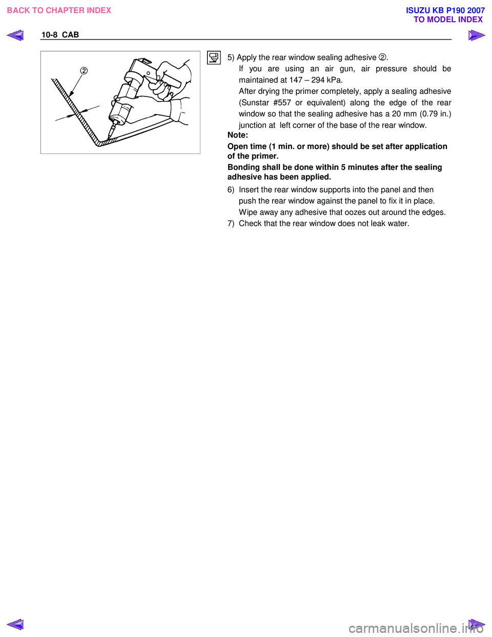
5) Apply the rear window sealing adhesive 2.
If you are using an air gun, air pressure should be maintained at 147 – 294 kPa.
After drying the primer completely, apply a sealing adhesive (Sunstar #557 or equivalent) along the edge of the rea
r
window so that the sealing adhesive has a 20 mm (0.79 in.)
junction at left corner of the base of the rear window.
Note:
Open time (1 min. or more) should be set after application
of the primer.
Bonding shall be done within 5 minutes after the sealing
adhesive has been applied.
6) Insert the rear window supports into the panel and then push the rear window against the panel to fix it in place.
W ipe away any adhesive that oozes out around the edges.
7) Check that the rear window does not leak water.
BACK TO CHAPTER INDEX TO MODEL INDEX
ISUZU KB P190 2007
Page 5769 of 6020
CAB 10-11
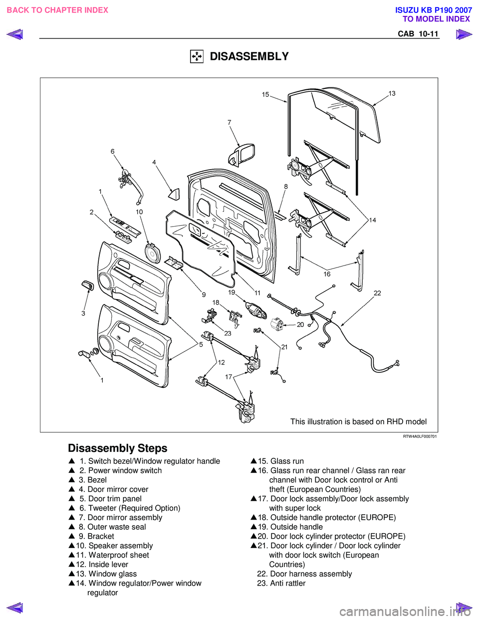
DISASSEMBLY
This illustration is based on RHD model
RTW 4A0LF000701
Disassembly Steps
▲ 1 . Switch bezel/W indow regulator handle
▲ 2. Power window switch
▲ 3. Bezel
▲ 4. Door mirror cover
▲ 5. Door trim panel
▲ 6. Tweeter (Required Option)
▲ 7. Door mirror assembly
▲ 8. Outer waste seal
▲ 9. Bracket
▲ 10. Speaker assembly
▲ 11 . W aterproof sheet
▲ 12. Inside lever
▲ 13. W indow glass
▲ 14. W indow regulator/Power window
regulator
▲
15. Glass run
▲ 16. Glass run rear channel / Glass ran rear
channel with Door lock control or Anti
theft (European Countries)
▲ 17. Door lock assembly/Door lock assembly
with super lock
▲ 18. Outside handle protector (EUROPE)
▲ 19. Outside handle
▲ 20. Door lock cylinder protector (EUROPE)
▲ 21. Door lock cylinder / Door lock cylinder
with door lock switch (European
Countries)
22. Door harness assembly
23. Anti rattler
BACK TO CHAPTER INDEX TO MODEL INDEX
ISUZU KB P190 2007
Page 5770 of 6020
10-12 CAB
RUW 5A0SH002201
Important Operations
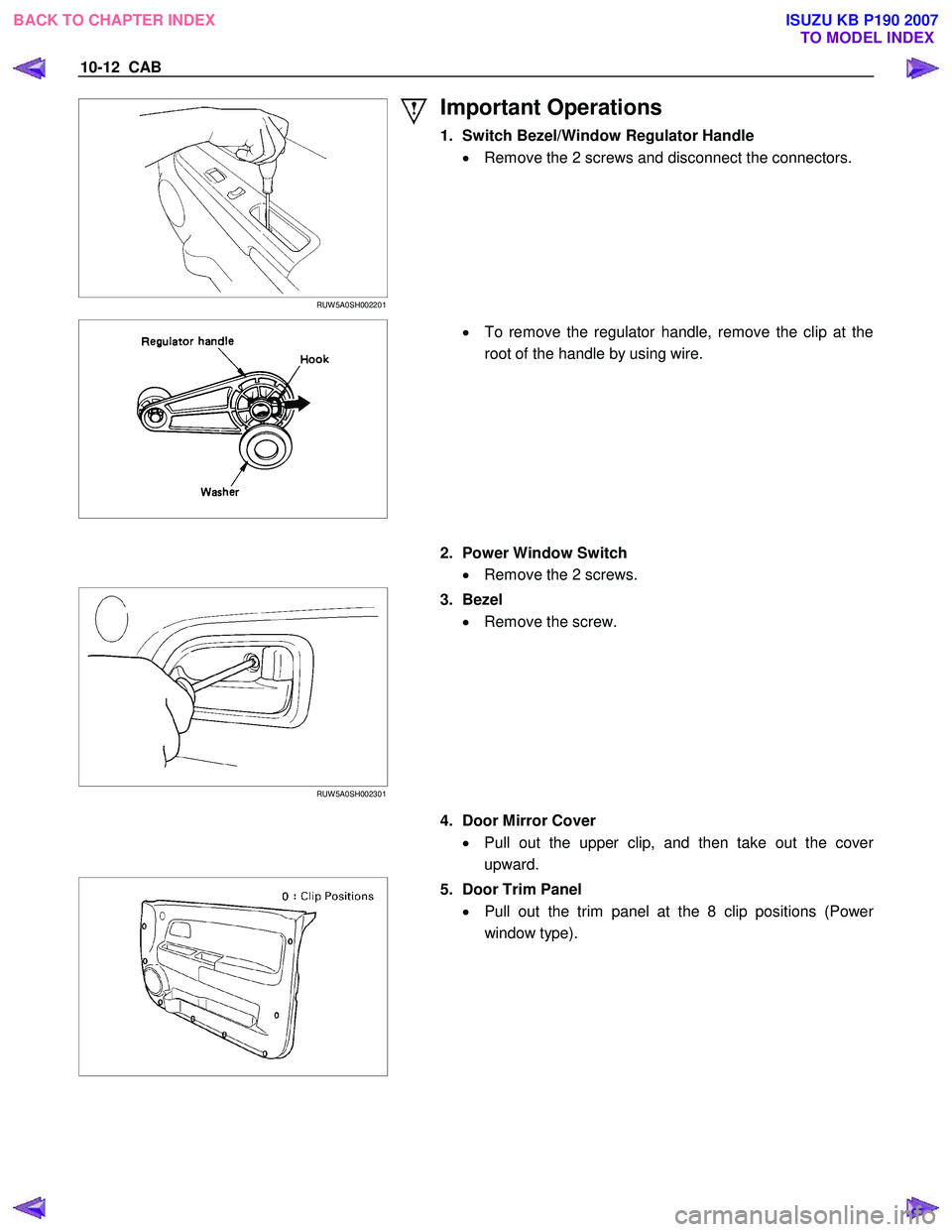
1. Switch Bezel/Window Regulator Handle
• Remove the 2 screws and disconnect the connectors.
•
To remove the regulator handle, remove the clip at the
root of the handle by using wire.
2. Power Window Switch
• Remove the 2 screws.
RUW 5A0SH00230 1
3. Bezel
• Remove the screw.
4. Door Mirror Cover
• Pull out the upper clip, and then take out the cove
r
upward.
5. Door Trim Panel
• Pull out the trim panel at the 8 clip positions (Powe
r
window type).
BACK TO CHAPTER INDEX TO MODEL INDEX
ISUZU KB P190 2007