2007 ISUZU KB P190 window
[x] Cancel search: windowPage 3153 of 6020
Engine Cooling – V6 Engine Page 6B1–18
Topping Up the Cooling System
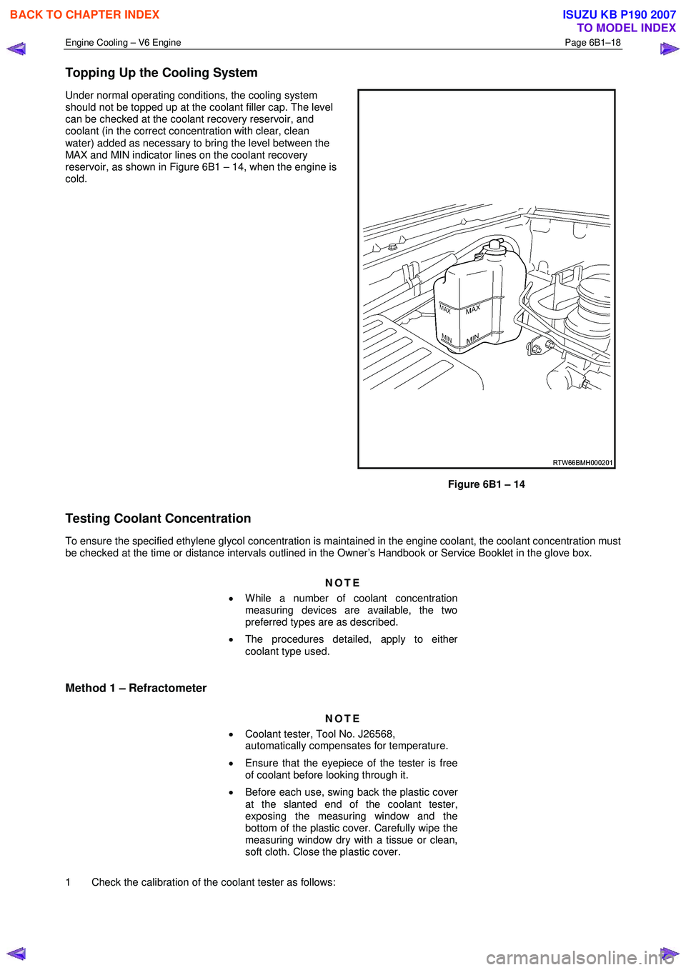
Under normal operating conditions, the cooling system
should not be topped up at the coolant filler cap. The level
can be checked at the coolant recovery reservoir, and
coolant (in the correct concentration with clear, clean
water) added as necessary to bring the level between the
MAX and MIN indicator lines on the coolant recovery
reservoir, as shown in Figure 6B1 – 14, when the engine is
cold.
Figure 6B1 – 14
Testing Coolant Concentration
To ensure the specified ethylene glycol concentration is maintained in the engine coolant, the coolant concentration must
be checked at the time or distance intervals outlined in the Owner’s Handbook or Service Booklet in the glove box.
NOTE
• While a number of coolant concentration
measuring devices are available, the two
preferred types are as described.
• The procedures detailed, apply to either
coolant type used.
Method 1 – Refractometer
NOTE
• Coolant tester, Tool No. J26568,
automatically compensates for temperature.
• Ensure that the eyepiece of the tester is free
of coolant before looking through it.
• Before each use, swing back the plastic cover
at the slanted end of the coolant tester,
exposing the measuring window and the
bottom of the plastic cover. Carefully wipe the
measuring window dry with a tissue or clean,
soft cloth. Close the plastic cover.
1 Check the calibration of the coolant tester as follows:
BACK TO CHAPTER INDEX
TO MODEL INDEX
ISUZU KB P190 2007
Page 3154 of 6020
Engine Cooling – V6 Engine Page 6B1–19
a Place a few drops of distilled water (between 21 and 29° C) onto the measuring window, then close the
plastic cover.
b Point the tester toward any light source, look into the eyepiece and check that the indicated reading is zero. If not, then re-calibrate the tester as detailed at the end of this Test Method, Calibrating the Tester.
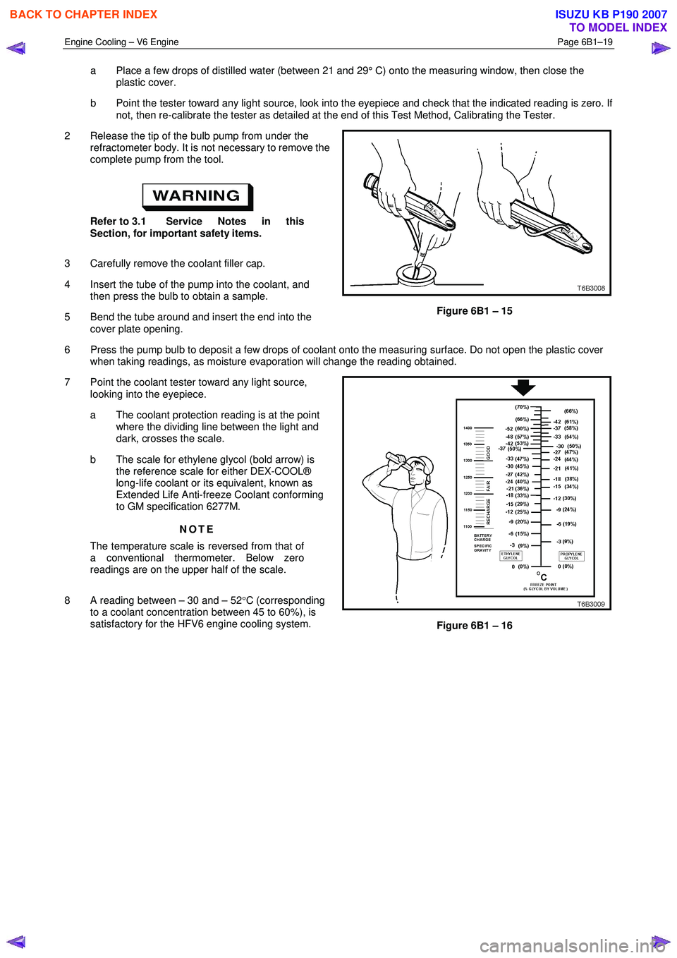
2 Release the tip of the bulb pump from under the refractometer body. It is not necessary to remove the
complete pump from the tool.
Refer to 3.1 Service Notes in this
Section, for important safety items.
3 Carefully remove the coolant filler cap.
4 Insert the tube of the pump into the coolant, and then press the bulb to obtain a sample.
5 Bend the tube around and insert the end into the cover plate opening.
Figure 6B1 – 15
6 Press the pump bulb to deposit a few drops of coolant onto the measuring surface. Do not open the plastic cover when taking readings, as moisture evaporation will change the reading obtained.
7 Point the coolant tester toward any light source, looking into the eyepiece.
a The coolant protection reading is at the point where the dividing line between the light and
dark, crosses the scale.
b The scale for ethylene glycol (bold arrow) is the reference scale for either DEX-COOL®
long-life coolant or its equivalent, known as
Extended Life Anti-freeze Coolant conforming
to GM specification 6277M.
NOTE
The temperature scale is reversed from that of
a conventional thermometer. Below zero
readings are on the upper half of the scale.
8 A reading between – 30 and – 52 °C (corresponding
to a coolant concentration between 45 to 60%), is
satisfactory for the HFV6 engine cooling system.
Figure 6B1 – 16
BACK TO CHAPTER INDEX
TO MODEL INDEX
ISUZU KB P190 2007
Page 3651 of 6020
Battery Page 6D1-3–11
b W ait 15 seconds for the battery to recover.
8 If possible, set the selector to 50% of rapid discharge current (or three times the 20 hour discharge rate).
9 Apply the load test for 10 seconds and record the battery voltage. If one cell is faulty it will gas excessively or overheat. This indicates a faulty battery.
10 Recharge the battery if the voltage is at or below the minimum voltage specified by the HRD manufacturer (or 9.6 V).
11 Replace the battery if the voltage is below the minimum voltage specified by the HRD manufacturer (or below 9.6 V after the battery is charged and the test is repeated). Refer to 4.1 Battery.
12 Connect the battery positive terminal.
13 Connect the battery negative terminal.
Alternate Load Test
If HRD test equipment is not available, test the battery as follows:
1 Read and obey the safety precautions for working with batteries, refer to 2 Safety Precautions.
2 Ensure the state of the battery is at least 65% charged. Refer to 3.3 Hydrometer Test.
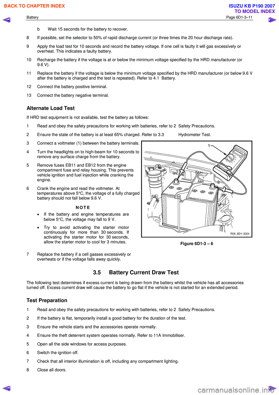
3 Connect a voltmeter (1) between the battery terminals.
4 Turn the headlights on to high-beam for 10 seconds to remove any surface charge from the battery.
5 Remove fuses EB11 and EB12 from the engine compartment fuse and relay housing. This prevents
vehicle ignition and fuel injection while cranking the
engine.
6 Crank the engine and read the voltmeter. At temperatures above 5°C, the voltage of a fully charged
battery should not fall below 9.6 V.
NOTE
• If the battery and engine temperatures are
below 5 °C, the voltage may fall to 9 V.
• Try to avoid activating the starter motor
continuously for more than 30 seconds. If
activating the starter motor for 30 seconds,
allow the starter motor to cool for 3 minutes.
7 Replace the battery if a cell gasses excessively or overheats or if the voltage falls away quickly.
Figure 6D1-3 – 6
3.5 Battery Current Draw Test
The following test determines if excess current is being drawn from the battery whilst the vehicle has all accessories
turned off. Excess current draw will cause the battery to go flat if the vehicle is not started for an extended period.
Test Preparation
1 Read and obey the safety precautions for working with batteries, refer to 2 Safety Precautions.
2 If the battery is flat, temporarily install a good battery for the duration of the test.
3 Ensure the vehicle starts and the accessories operate normally.
4 Ensure the theft deterrent system operates normally. Refer to 11A Immobiliser.
5 Open all the side windows for access purposes.
6 Switch the ignition off.
7 Check that all interior illumination is off, including any compartment lighting.
8 Close all doors.
BACK TO CHAPTER INDEX
TO MODEL INDEX
ISUZU KB P190 2007
Page 3823 of 6020
Automatic Transmission – 4L60E – Electrical Diagnosis Page 7C2–37
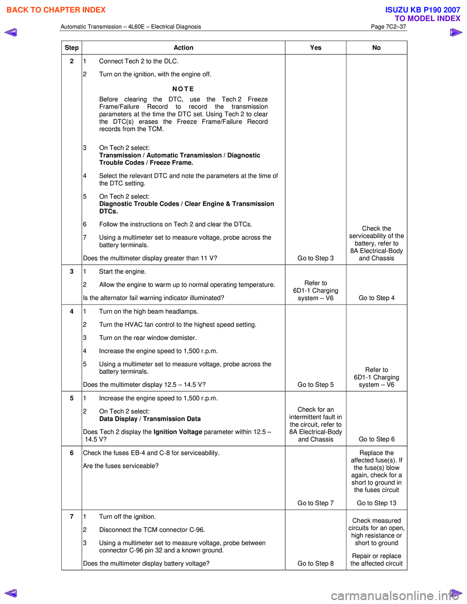
Step Action Yes No
2 1 Connect Tech 2 to the DLC.
2 Turn on the ignition, with the engine off.
NOTE
Before clearing the DTC, use the Tech 2 Freeze
Frame/Failure Record to record the transmission
parameters at the time the DTC set. Using Tech 2 to clear
the DTC(s) erases the Freeze Frame/Failure Record
records from the TCM.
3 On Tech 2 select: Transmission / Automatic Transmission / Diagnostic
Trouble Codes / Freeze Frame.
4 Select the relevant DTC and note the parameters at the time of the DTC setting.
5 On Tech 2 select:
Diagnostic Trouble Codes / Clear Engine & Transmission
DTCs.
6 Follow the instructions on Tech 2 and clear the DTCs.
7 Using a multimeter set to measure voltage, probe across the battery terminals.
Does the multimeter display greater than 11 V? Go to Step 3 Check the
serviceability of the battery, refer to
8A Electrical-Body and Chassis
3 1 Start the engine.
2 Allow the engine to warm up to normal operating temperature.
Is the alternator fail warning indicator illuminated? Refer to
6D1-1 Charging system – V6 Go to Step 4
4 1 Turn on the high beam headlamps.
2 Turn the HVAC fan control to the highest speed setting.
3 Turn on the rear window demister.
4 Increase the engine speed to 1,500 r.p.m.
5 Using a multimeter set to measure voltage, probe across the battery terminals.
Does the multimeter display 12.5 – 14.5 V? Go to Step 5 Refer to
6D1-1 Charging system – V6
5 1 Increase the engine speed to 1,500 r.p.m.
2 On Tech 2 select: Data Display / Transmission Data
Does Tech 2 display the Ignition Voltage parameter within 12.5 –
14.5 V? Check for an
intermittent fault in the circuit, refer to
8A Electrical-Body
and Chassis Go to Step 6
6
Check the fuses EB-4 and C-8 for serviceability.
Are the fuses serviceable?
Go to Step 7 Replace the
affected fuse(s). If the fuse(s) blow
again, check for a short to ground in the fuses circuit
Go to Step 13
7 1 Turn off the ignition.
2 Disconnect the TCM connector C-96.
3 Using a multimeter set to measure voltage, probe between connector C-96 pin 32 and a known ground.
Does the multimeter display battery voltage? Go to Step 8 Check measured
circuits for an open,
high resistance or short to ground
Repair or replace
the affected circuit
BACK TO CHAPTER INDEX
TO MODEL INDEX
ISUZU KB P190 2007
Page 3994 of 6020
![ISUZU KB P190 2007 Workshop Repair Manual 7A2-28 TRANSMISSION CONTROL SYSTEM (AW30–40LE)
Graph display Values and graphs (Max. 3 graphs):
1. Click the icon for graph display. [Graph Parameter]
window opens.
2. Click the fir ISUZU KB P190 2007 Workshop Repair Manual 7A2-28 TRANSMISSION CONTROL SYSTEM (AW30–40LE)
Graph display Values and graphs (Max. 3 graphs):
1. Click the icon for graph display. [Graph Parameter]
window opens.
2. Click the fir](/manual-img/61/57177/w960_57177-3993.png)
7A2-28 TRANSMISSION CONTROL SYSTEM (AW30–40LE)
Graph display Values and graphs (Max. 3 graphs):
1. Click the icon for graph display. [Graph Parameter]
window opens.
2. Click the first graph icon of the window upper part,
and select one parameter from the list of the
window lower part. Selected parameter is
displayed next to the graph icon. Graph division
can be selected in the field on the parameter right
side.
3. Repeat the same procedures with the 2nd and 3rd
icons.
4.
After selecting all parameters to be displayed
(Max. 3 parameters), click [OK] button.
5. Parameter selected is displayed in graph form on
the right of the data parameter on the screen.
6. Graph display can be moved with the navigation
icon.
7. For displaying another parameter by graph, click
the parameter of the list, drug the mouse to the
display screen while pressing the mouse button
and release the mouse button. New parameter is
displayed at the position of the previous
parameter. For displaying the graph display screen
in full size, move the cursor upward on the screen.
W hen the cursor is changed to the magnifying
glass form, click the screen. Graph screen is
displayed on the whole screen.
BACK TO CHAPTER INDEX
TO MODEL INDEX
ISUZU KB P190 2007
Page 4941 of 6020
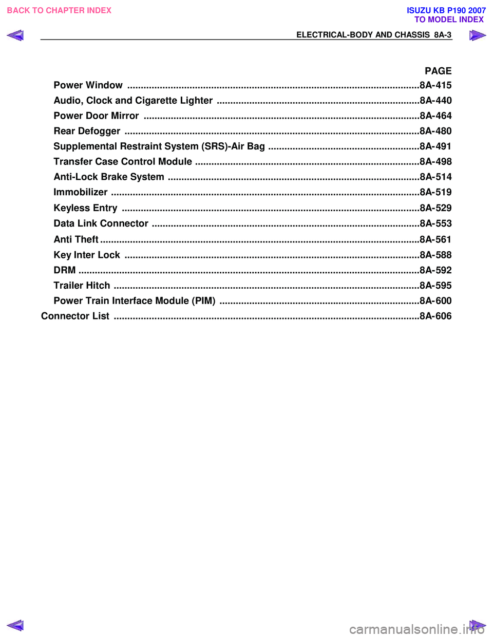
ELECTRICAL-BODY AND CHASSIS 8A-3
PAGE
Power Window ............................................................................................................8A- 41 5
Audio, Clock and Cigarette Lighter ...........................................................................8A- 440
Power Door Mirror ......................................................................................................8A- 464
Rear Defogger .............................................................................................................8A- 480
Supplemental Restraint System (SRS)-Air Bag ........................................................8A- 491
Transfer Case Control Module ...................................................................................8A- 498
Anti-Lock Brake System .............................................................................................8A- 514
Immobilizer ..................................................................................................................8 A- 519
Keyless Entry ..............................................................................................................8A- 529
Data Link Connector ...................................................................................................8A- 553
Anti Theft ..................................................................................................................... .8A- 561
Key Inter Lock .............................................................................................................8A- 588
DRM ........................................................................................................................... ...8A- 592
Trailer Hitch ................................................................................................................. 8A- 595
Power Train Interface Module (PIM) ..........................................................................8A- 600
Connector List ................................................................................................................ .8A- 606
BACK TO CHAPTER INDEX
TO MODEL INDEX
ISUZU KB P190 2007
Page 4971 of 6020
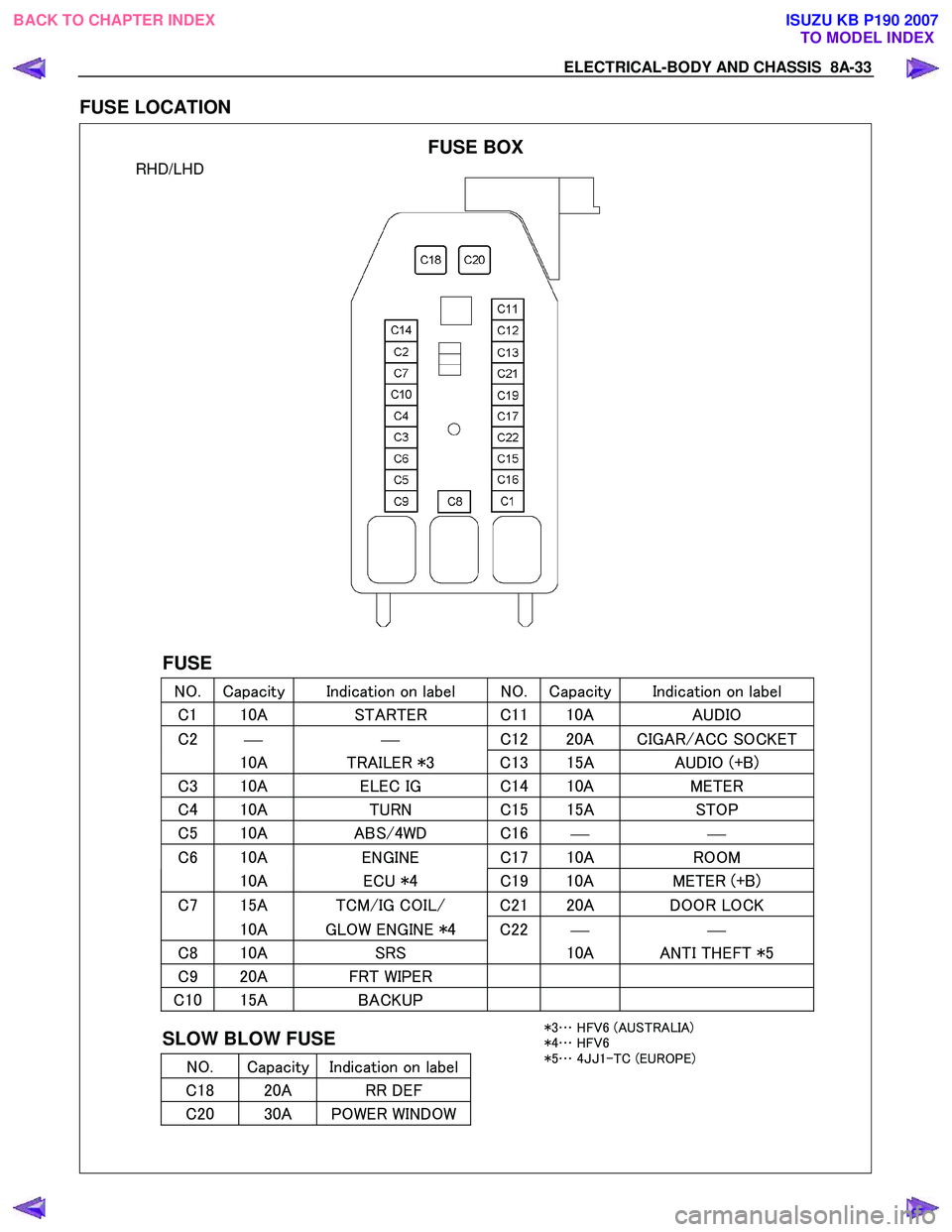
ELECTRICAL-BODY AND CHASSIS 8A-33
FUSE LOCATION
RHD/LHD
FUSE
NO. Capacity Indication on label NO. Capacity Indication on label
C 1 10A STARTER C 1110A AUDIO
C2
C
12 20A CIGAR/ACC SOCKET
10A TRAILER *3 C 13 15A AUDIO (+B)
C3 10A ELEC IG C 14 10A METER
C4 10A TURN C 15 15A STOP
C5 10A ABS/4WD C 16
C6 10A ENGINE C 17 10A ROOM
10A ECU *4 C19 10A METER (+B)
C7 15A TCM/IG COIL/ C2 120A DOOR LOCK
10A GLOW ENGINE *4 C22
C8 10A SRS 10A ANTI THEFT *5
C9 20A FRT WIPER
C10 15A BACKUP
SLOW BLOW FUSE
NO. Capacity Indication on label
C 18 20A RR DEF
C20 30A POWER WINDOW
FUSE BOX
*3 … HFV6 (AUSTRALIA)
*4 … HFV6
*5 … 4JJ 1-TC (EUROPE)
BACK TO CHAPTER INDEX
TO MODEL INDEXISUZU KB P190 2007
Page 5332 of 6020
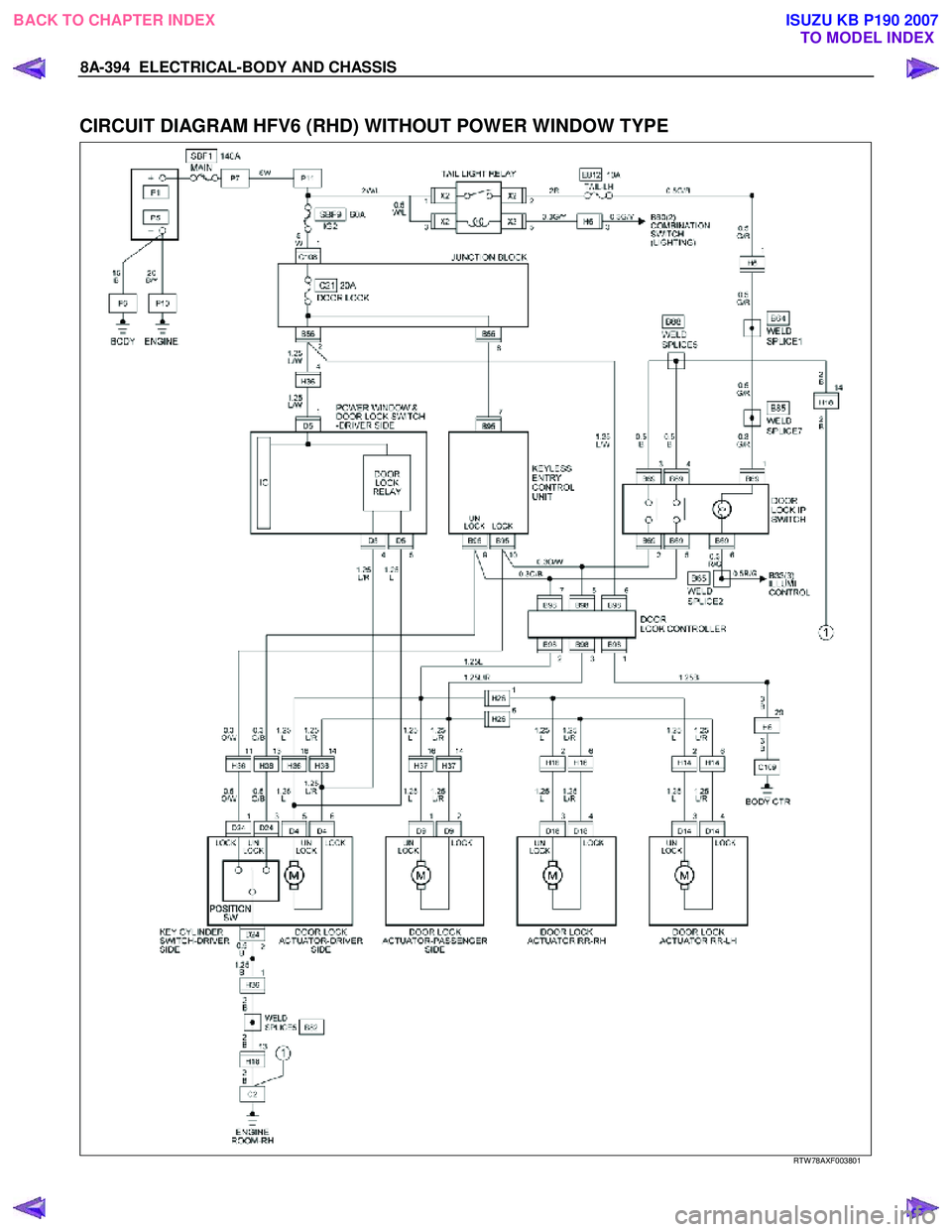
8A-394 ELECTRICAL-BODY AND CHASSIS
CIRCUIT DIAGRAM HFV6 (RHD) WITHOUT POWER WINDOW TYPE
RTW 78AXF003801
BACK TO CHAPTER INDEX
TO MODEL INDEXISUZU KB P190 2007