2007 ISUZU KB P190 brake fluid
[x] Cancel search: brake fluidPage 3843 of 6020
Automatic Transmission – 4L60E – Electrical Diagnosis Page 7C2–57
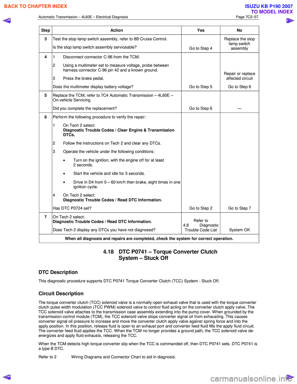
Step Action Yes No
3 Test the stop lamp switch assembly, refer to 8B Cruise Control.
Is the stop lamp switch assembly serviceable? Go to Step 4 Replace the stop
lamp switch assembly
4 1 Disconnect connector C-96 from the TCM.
2 Using a multimeter set to measure voltage, probe between harness connector C-96 pin 42 and a known ground.
3 Press the brake pedal.
Does the multimeter display battery voltage? Go to Step 5 Repair or replace
affected circuit
Go to Step 6
5 Replace the TCM, refer to 7C4 Automatic Transmission – 4L60E –
On-vehicle Servicing.
Did you complete the replacement? Go to Step 6 —
6 Perform the following procedure to verify the repair:
1 On Tech 2 select: Diagnostic Trouble Codes / Clear Engine & Transmission
DTCs.
2 Follow the instructions on Tech 2 and clear any DTCs.
3 Operate the vehicle under the following conditions:
• Turn on the ignition, with the engine off for at least
2 seconds.
• Start the vehicle and idle for 5 seconds.
• Drive in D4 from 0 – 60 km/h then brake, eight times in one
ignition cycle.
4 On Tech 2 select:
Diagnostic Trouble Codes / Read DTC Information.
Has DTC P0724 set? Go to Step 2 Go to Step 7
7 On Tech 2 select:
Diagnostic Trouble Codes / Read DTC Information.
Does Tech 2 display any DTCs you have not diagnosed? Refer to
4.8 Diagnostic Trouble Code List System OK
When all diagnosis and repairs are completed, check the
system for correct operation.
4.18 DTC P0741 – Torque Converter Clutch
System – Stuck Off
DTC Description
This diagnostic procedure supports DTC P0741 Torque Converter Clutch (TCC) System - Stuck Off.
Circuit Description
The torque converter clutch (TCC) solenoid valve is a normally-open exhaust valve that is used with the torque converter
clutch pulse width modulation (TCC PWM) solenoid valve to control fluid acting on the converter clutch apply valve. The
TCC solenoid valve attaches to the transmission case assembly extending into the pump cover. W hen grounded by the
transmission control module (TCM), the TCC solenoid valve stops converter signal oil from exhausting. This causes
converter signal oil pressure to increase and move the converter clutch apply valve against spring force and into the
apply position. In this position, release fluid is open to an exhaust port and converter feed fluid fills the apply fluid circu it.
The converter feed fluid applies the TCC. When the TCM no longer provides a ground path, the TCC solenoid valve de-
energizes and apply fluid exhausts, releasing the TCC.
When the TCM detects high torque converter slip when the TCC is commanded off, then DTC P0741 sets. DTC P0741 is
a type B DTC.
Refer to 2 W iring Diagrams and Connector Chart to aid in diagnosis.
BACK TO CHAPTER INDEX
TO MODEL INDEX
ISUZU KB P190 2007
Page 3847 of 6020
Automatic Transmission – 4L60E – Electrical Diagnosis Page 7C2–61
• The vehicle speed is greater than 15 km/h.
• TCC is commanded off.
Conditions for Setting the DTC
The following conditions occur four times in one ignition cycle:
• The TCM commands the TCC off.
• The TCC slip is -15 – +15 r.p.m. for greater than 3 seconds.
Action Taken When the DTC Sets
•
The TCM requests the ECM to illuminate the MIL during the second consecutive drive trip in which the conditions
for setting the DTC are met.
• The TCM commands maximum line pressure.
• The TCM freezes transmission adaptive functions.
• At the time of the first failure, the TCM records the operating conditions when the conditions for setting the DTC are
met. The TCM stores this information as a Failure Record.
• At the time of the second failure, the ECM records the operating conditions when the conditions for setting the DTC
are met. The ECM stores this information as a Freeze Frame.
• The TCM stores DTC P0742 in TCM history.
Conditions for Clearing the DTC
• The ECM turns off the MIL after the sixth consecutive drive trip in which the TCM does not send a MIL illumination
request.
• Tech 2 can clear the DTC.
• The TCM clears the DTC from TCM history if the vehicle completes 40 warm-up cycles without a non-emission
related diagnostic fault occurring.
• The TCM cancels the default actions when the ignition is off long enough to power down the TCM.
Diagnostic Aids
The TCC fluid hydraulically applies the TCC, possibly causing an engine stall, under the following conditions:
• The TCC is hydraulically stuck in the on position
• The parking brake is applied.
• Any gear range is selected.
• Contamination may cause the TCC apply valve to intermittently stick in the valve body.
• Internal damage in the torque converter may cause no TCC apply.
Test Description
The following numbers refer to the step numbers in the diagnostic table:
2 This step tests the hydraulic state of the TCC. W hen the TCM commands the TCC solenoid valve off, the slip speed should increase.
3 Checks the mechanical components that cause the DTC and their state.
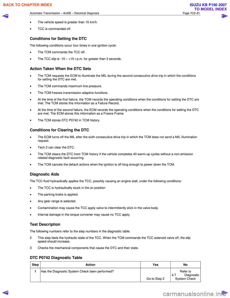
DTC P0742 Diagnostic Table
Step Action Yes No
1 Has the Diagnostic System Check been performed?
Go to Step 2 Refer to
4.7 Diagnostic
System Check
BACK TO CHAPTER INDEX
TO MODEL INDEX
ISUZU KB P190 2007
Page 3918 of 6020
Automatic Transmission – 4L60E – On-vehicle Servicing Page 7C4–5
2 Maintenance Operations
2.1 Transmission Fluid
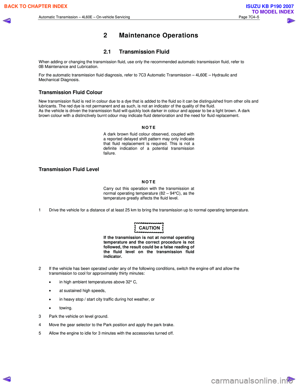
When adding or changing the transmission fluid, use only the recommended automatic transmission fluid, refer to
0B Maintenance and Lubrication.
For the automatic transmission fluid diagnosis, refer to 7C3 Automatic Transmission – 4L60E – Hydraulic and
Mechanical Diagnosis.
Transmission Fluid Colour
New transmission fluid is red in colour due to a dye that is added to the fluid so it can be distinguished from other oils and
lubricants. The red dye is not permanent and as such, is not an indicator of the quality of the fluid.
As the vehicle is driven the transmission fluid will quickly look darker in colour and appear to be a light brown. A dark
brown colour with a distinctively burnt odour may indicate fluid deterioration and the need for fluid replacement.
NOTE
A dark brown fluid colour observed, coupled with
a reported delayed shift pattern may only indicate
that fluid replacement is required. This is not a
definite indication of a potential transmission
failure.
Transmission Fluid Level
NOTE
Carry out this operation with the transmission at
normal operating temperature (82 – 94°C), as the
temperature greatly affects the fluid level.
1 Drive the vehicle for a distance of at least 25 km to bring the transmission up to normal operating temperature.
If the transmission is not at normal operating
temperature and the correct procedure is not
followed, the result could be a false reading of
the fluid level on the transmission fluid
indicator.
2 If the vehicle has been operated under any of the following conditions, switch the engine off and allow the transmission to cool for approximately thirty minutes:
• in high ambient temperatures above 32° C,
• at sustained high speeds,
• in heavy stop / start city traffic during hot weather, or
• towing.
3 Park the vehicle on level ground.
4 Move the gear selector to the Park position and apply the park brake.
5 Allow the engine to idle for 3 minutes with the accessories turned off.
BACK TO CHAPTER INDEX
TO MODEL INDEX
ISUZU KB P190 2007
Page 3990 of 6020
7A2-24 TRANSMISSION CONTROL SYSTEM (AW30–40LE)
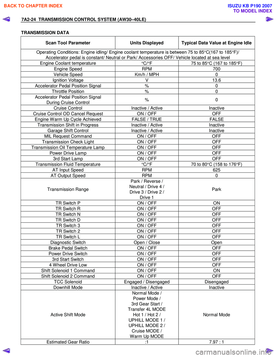
TRANSMISSION DATA
Scan Tool Parameter Units Displayed Typical Data Value at Engine Idle
Operating Conditions: Engine idling/ Engine coolant temperature is between 75 to 85 °C(167 to 185 °F)/
Accelerator pedal is constant/ Neutral or Park/ Accessories OFF/ Vehicle located at sea level
Engine Coolant temperature °C/ °F 75 to 85°C (167 to 185 °F)
Engine Speed RPM 700
Vehicle Speed Km/h / MPH 0
Ignition Voltage V 13.6
Accelerator Pedal Position Signal % 0
Throttle Position % 0
Accelerator Pedal Position Signal
During Cruise Control % 0
Cruise Control
Inactive / Active Inactive
Cruise Control OD Cancel Request ON / OFF OFF
Engine W arm Up Cycle Achieved FALSE / TRUE FALSE
Transmission Shift in Progress Inactive / Active Inactive
Garage Shift Control Inactive / Active Inactive
MIL Request Command ON / OFF OFF
Transmission Check Light ON / OFF OFF
Transmission Oil Temperature Lamp ON / OFF OFF
Power Drive Lamp ON / OFF OFF
3rd Start Lamp ON / OFF OFF
Transmission Fluid Temperature
°C/ °F 70 to 80°C (158 to 176 °F)
AT Input Speed RPM 625
AT Output Speed RPM 0
Transmission Range Park / Reverse /
Neutral / Drive 4 / Drive 3 / Drive 2 / Drive 1 Park
TR Switch P
ON / OFF ON
TR Switch R ON / OFF OFF
TR Switch N ON / OFF OFF
TR Switch D ON / OFF OFF
TR Switch 3 ON / OFF OFF
TR Switch 2 ON / OFF OFF
TR Switch L ON / OFF OFF
Diagnostic Switch Open / Close Open
Brake Pedal Switch ON / OFF OFF
Power Drive Switch ON / OFF OFF
3rd Start Switch ON / OFF OFF
4 W heel Drive Low ON / OFF OFF
Shift Solenoid 1 Command ON / OFF ON
Shift Solenoid 2 Command ON / OFF OFF
TCC Solenoid Engaged / Disengaged Disengaged
Downhill Mode Inactive / Active Inactive
Active Shift Mode Normal Mode /
Power Mode /
3rd Gear Start /
Transfer 4L MODE Hot 1 / Hot 2 /
UPHILL MODE 1 /
UPHILL MODE 2 / Cruise MODE /
W arm Up MODE Normal Mode
Estimated Gear Ratio
:1 7.97 : 1
BACK TO CHAPTER INDEX
TO MODEL INDEX
ISUZU KB P190 2007
Page 4086 of 6020
ON-VEHICLE SERVICE (AW30–40LE) 7A3-1
SECTION 7A3
ON-VEHICLE SERVICE (AW30–40LE)
TABLE OF CONTENTS
Service Precaution .................................................. 7A3-2
Diagnosis ................................................................. 7A3-3
Basic Troubleshooting ........................................ 7A3-3
Manual Shifting Test ........................................... 7A3-9
Stall Test ............................................................... 7A3-9
Time Lag Test ...................................................... 7A3-10
Hydraulic Test ...................................................... 7A3-11
Road Test ............................................................. 7A3-12
Shift Point Chart and Lock-Up Point Chart ..........7A3-16
Shift Point Chart ................................................... 7A3-16
Lock-Up Point Chart ............................................ 7A3-17
Transmission Fluid Level and Condition ..............7A3-18
Inspection ............................................................. 7A3-18
ATF Replacement ................................................... 7A3-19
Inspection ............................................................. 7A3-19
Neutral Start Switch (Mode Switch) ......................7A3-20
Inspection ............................................................. 7A3-20
Removal ................................................................ 7A3-20
Installation ............................................................. 7A3-20
Brake Signal ............................................................ 7A3-21
Inspection ............................................................. 7A3-21
Input and Output Revolution Sensor ....................7A3-22
Inspection ............................................................. 7A3-22
Power and 3rd Start switch ....................................7A3-22
Inspection ............................................................. 7A3-22
Solenoid .................................................................... 7A3-23
Inspection ............................................................. 7A3-23
ATF Temperature Sensor ......................................7A3-24
Inspection ............................................................. 7A3-24
Select Lever ....................................................... 7A3-25 Remove or Disconnect .......................................7A3-26
Install or Connect ................................................ 7A3-26
Shift Cable .......................................................... 7A3-28 Remove or Disconnect .......................................7A3-28
Install or Connect ................................................ 7A3-29
Torque Specifications ......................................... 7A3-30
Transmission Control Module (TCM) ...................7A3-31
Removal ............................................................... 7A3-31
Installation ............................................................ 7A3-31
Shift Solenoid and Lock-Up Solenoid ..................7A3-32
Removal ............................................................... 7A3-32
Installation ............................................................ 7A3-33
Valve Body Assembly and Pressure Control Solenoid ................................................. 7A3-34
Removal ............................................................... 7A3-34
Installation ............................................................ 7A3-36
Rear Oil Seal (Adapter Housing, 4 ×4) ................. 7A3-37
Removal ............................................................... 7A3-37
Installation ............................................................ 7A3-37
Rear Oil Seal (Extension Housing, 4 ×2) .............. 7A3-38
Removal ............................................................... 7A3-38
Installation ............................................................ 7A3-38
Transmission Assembly .........................................7A3-39
Transmission and Associated Parts .................7A3-39
Removal ............................................................... 7A3-40
Installation ............................................................ 7A3-44
Major Components .............................................. 7A3-49
BACK TO CHAPTER INDEX
TO MODEL INDEX
ISUZU KB P190 2007
Page 4095 of 6020
7A3-10 ON-VEHICLE SERVICE (AW30–40LE)
Measure Stall Speed
1. Chock the four wheels.
2. Mount an engine tachometer.
3. Fully apply the parking brake.
4. Step down strongly on the brake pedal with your left foot. (Keep the state until the test is completed)
5. Start the engine.
6. Turn off the A/C.
7. Select into the “D" position. Step all the way down on the accelerator pedal with your right foot. Quickl
y
record the highest speed as soon as the engine
speed gets stabilized.
8. Select into the “N” position and maintain the engine
idling condition more than 1 minute.
Stall speed: 2300 ±
±±
±
200 rpm *
* Ambient temperature to be between roughly 10 °C
(50 °F) and 40 °C (104 °F).
Evaluation
1. If the engine speed is the same for both positions
but lower than the specified value:
• Engine output is insufficient.
• Stator one-way clutch is not operating properly.
NOTE: If more than 600 rpm below the specified value,
the torque converter could be faulty.
2. If the stall speed in “D" position is higher than
specified:
• Line pressure too low
• Forward clutch slipping
• No.2 one-way clutch not operating properly
3. If the stall speed in “R" position is higher than
specified:
• Line pressure too low
• Direct clutch slipping
• No.3 brake slipping
4. If the stall speed in the “R" and “D" positions are
higher than specified:
• Line pressure too low
• Improper fluid level
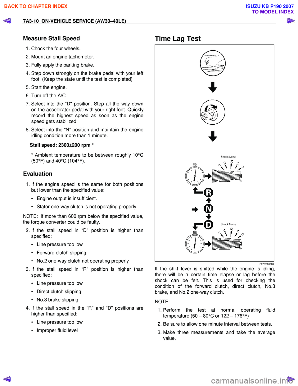
Time Lag Test
F07RY00003
If the shift lever is shifted while the engine is idling,
there will be a certain time elapse or lag before the
shock can be felt. This is used for checking the
condition of the forward clutch, direct clutch, No.3
brake, and No.2 one-way clutch.
NOTE:
1. Perform the test at normal operating fluid
temperature (50 – 80 °C or 122 – 176 °F)
2. Be sure to allow one minute interval between tests.
3. Make three measurements and take the average value.
BACK TO CHAPTER INDEX
TO MODEL INDEX
ISUZU KB P190 2007
Page 4096 of 6020
ON-VEHICLE SERVICE (AW30–40LE) 7A3-11
Measure Time Lag
1. Fully apply the parking brake.
2. Start the engine. Check idling speed (A/C OFF).
3. Operate the select lever from “N" to “D" position.
Using a stopwatch, measure the time it takes from
shifting the lever until the shock is felt.
Time lag: Less than 0.7 seconds
4. In same manner, measure the time lag for “N" →
“R".
Time lag: Less than 1.2 seconds
Evaluation
1. If “N" → “D" time lag is longer than specified:
• Line pressure too low
• Forward clutch malfunction
• No.2 one-way clutch not operating properly
2. If “N" → “R" time lag is longer than specified:
• Line pressure too low
• Direct clutch malfunction
• First and Reverse brake malfunction
3. If both time lag is longer than specified:
• Line pressure too low
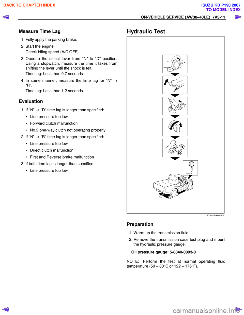
Hydraulic Test
RTW 67ALH000201
Preparation
1. W arm up the transmission fluid.
2. Remove the transmission case test plug and mount the hydraulic pressure gauge.
Oil pressure gauge: 5-8840-0093-0
NOTE: Perform the test at normal operating fluid
temperature (50 – 80 °C or 122 – 176 °F).
BACK TO CHAPTER INDEX
TO MODEL INDEX
ISUZU KB P190 2007
Page 4097 of 6020
7A3-12 ON-VEHICLE SERVICE (AW30–40LE)
Measure Line Pressure
1. Fully apply the parking brake and chock the four
wheels.
2. Start the engine and check idling rpm.
3. Select into “D" position, step down strongly on the brake pedal with your left foot and while
manipulating the accelerator pedal with the right
foot, measure the line pressures at the engine
speeds specified in the table.
4. In the same manner, perform the test in “R" position.
Line pressure kPa (kg/cm
2/psi) Engine
speed “D" position “R" position
Idling 349 – 408
(3.6 – 4.2 /51 – 59) 577 – 675
(5.9 – 6.9/84 – 98)
Stall 1,206 – 1,353
(12.3–13.8/175–196) 1,646 – 1,979
(16.8–20.2/239–287)
Evaluation
1. If the measured values at all positions are higher
than specified:
• Pressure control solenoid defective
• Primary regulator valve defective
2. If the measured values at all positions are lowe
r
than specified:
• Primary regulator valve defective
• Oil pump defective
• Pressure control solenoid defective
3. If pressure is low in “D" position only:
• “D" position circuit fluid leakage
4. If pressure is low in “R" position only:
• “R" position circuit fluid leakage
Road Test
NOTE: Perform the test at normal operating fluid
temperature (50 – 80 °C or 122 – 176 °F).
“D" Position Test in “NORMAL", and
“POWER" Pattern
Select into the “D" position and hold the accelerator
pedal constant at the 50% and 100% throttle valve
opening positions.
Push in one of the pattern selector buttons and check
the following:
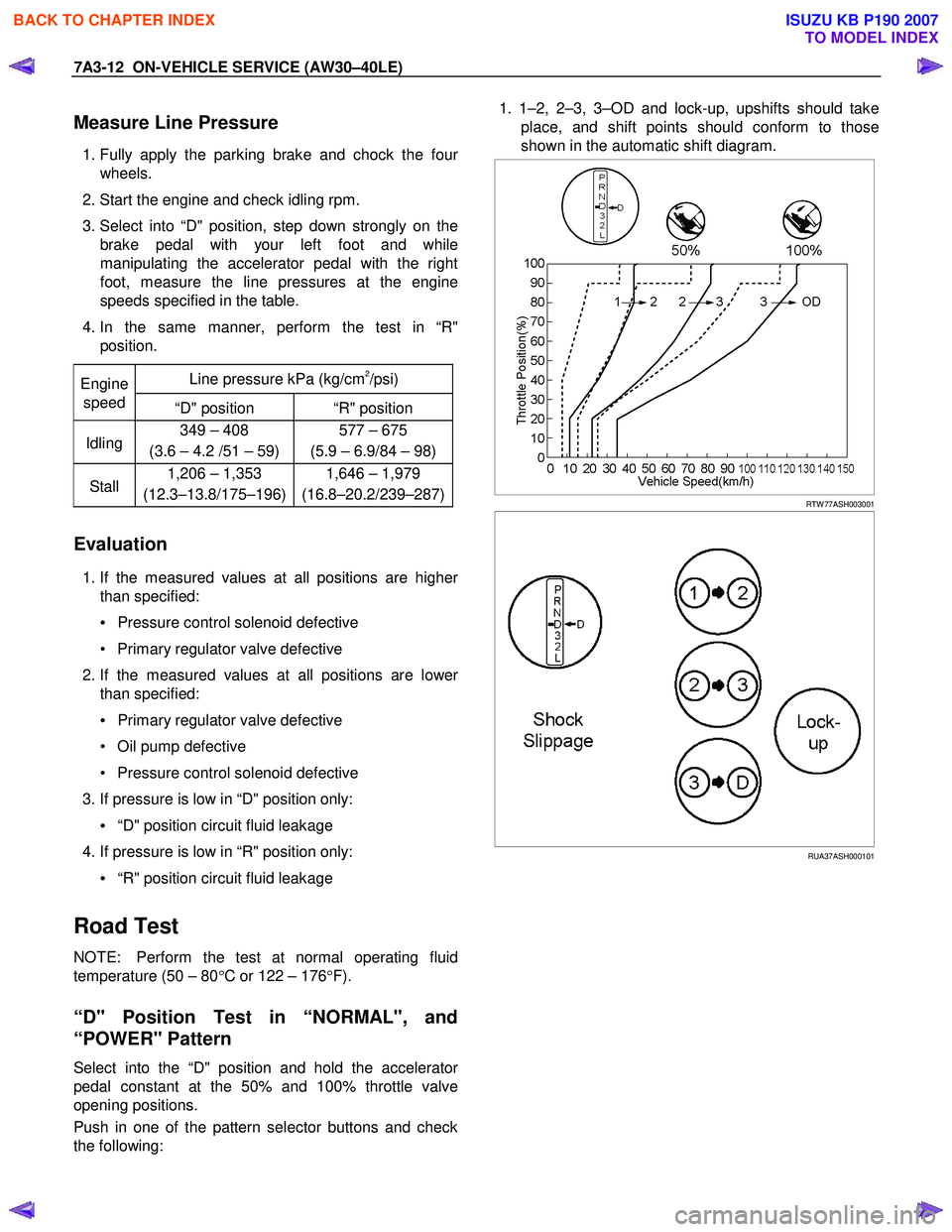
1. 1–2, 2–3, 3–OD and lock-up, upshifts should take
place, and shift points should conform to those
shown in the automatic shift diagram.
RTW 77ASH003001
RUA37ASH000101
BACK TO CHAPTER INDEX
TO MODEL INDEX
ISUZU KB P190 2007