2007 ISUZU KB P190 brake fluid
[x] Cancel search: brake fluidPage 757 of 6020

5C-58 BRAKES
RTW 75CSH002301
2. Primary Piston
Lubricate the piston cup on the primary piston assemblies with
brake fluid (1).
Note:
Be sure to use a new piston.
3. Guide Assembly
Lubricate the O-ring of guide assembly with brake fluid (2) and
the cup of guide assembly with rubber grease (3) (0.2 ~ 0.3g).
RTW 75CSH002001
4. Cylinder Body
Install the secondary piston and the primary piston to the
cylinder body.
Note:
The secondary piston long hole and the cylinder body stoppe
r
bolt hole must be aligned at installation.
5. Stopper Bolt and Gasket
Install the stopper bolt to the cylinder body (the piston long hole
must be aligned with the cylinder body installation hole).
Tighten the bolts to the specified torque.
Torque N ⋅m (kgf ⋅m/lb ⋅in)
2 - 3 (0.2 - 0.3 / 17 - 26)
6. Snap Ring
Press down on the primary piston and install the snap ring to
the cylinder body groove.
Note:
Be sure to use new snap ring.
7. Grommet
1. Install the grommets to the reservoir tank.
Note:
Be sure to use are new grommets.
2. Install the reservoir tank to the cylinder body.
8. Reservoir Tank
9. Pin
BACK TO CHAPTER INDEX
TO MODEL INDEX
ISUZU KB P190 2007
Page 760 of 6020

BRAKES 5C-61
RTW 75CSH002701
Important Operation-Removal
1. Brake pipe
W hen hurdling, be careful not to spill brake fluid over the
painted surfaces, as damage to the paint finish will result.
2. Master Cylinder Fixing Nut
3. Bracket
4. Master Cylinder Assembly
NOTE:
W hen removing the master cylinder from the vacuum booster,
be sure to get rid of the internal negative pressure of the
vacuum booster (by, for instance, disconnecting the vacuum
hose) in advance.
If any negative pressure remains in the vacuum booster, the
piston may possibly come out when the master cylinder is
being removed, letting the brake fluid run out.
W hile removing the master cylinder, do not hold the piston as it
can be easily pulled out.
Inspection and Repair
Vacuum Hose (The built in check valve)
360R300002
1) Inspect the check valve, which is installed inside the
vacuum hose.
2) Blow air into the hose from the booster side as shown in the illustration. The air should pass freely through the
hose.
3) Blow air into the hose from the engine side. The check valve should close to block the passage of air.
The vacuum hose and built-in check valve must be
replaced as a set if either is found to be defective.
Important Operation-Installation
10. Vacuum Booster Assembly
Note:
•
Adjustment of push rod of vacuum booster is not carried
out. W hen vacuum booster is damaged it exchanges for a
new article. (Push rod is adjusted)
• Measurement of primary piston position by the side o
f
master cylinder is unnecessary.
9. Spacer
8. Gasket
7. Vacuum Booster Fixing Nut
6. Snap Pin
Install the vacuum booster assembly to the dash panel and
pedal mounting bracket.
BACK TO CHAPTER INDEX
TO MODEL INDEX
ISUZU KB P190 2007
Page 2110 of 6020
6B-6 ENGINE COOLING
Draining and Refilling Cooling
System
Before draining the cooling system, inspect the system and
perform any necessary service to ensure that it is clean, does
not leak and is in proper working order. The engine coolant
level should be between the "MIN" and "MAX" lines of reserve
tank when the engine is cold. If low, check for leakage and add
engine coolant up to the "MAX" line. There should not be any
excessive deposit of rust or scales around the radiator cap or
radiator filler hole, and the engine coolant should also be free
from oil.
Replace the engine coolant if excessively dirty.
1. Completely drain the cooling system by opening the drain
plug at the bottom of the radiator.
2. Remove the radiator cap.
WARNING: TO AVOID THE DANGER OF BEING BURNED,
DO NOT REMOVE THE CAP WHILE THE ENGINE AND
RADIATOR ARE STILL HOT. SCALDING FLUID AND
STEAM CAN BE BLOWN OUT UNDER PRESSURE.
3. Disconnect all hoses from the engine coolant reserve tank.
Scrub and clean the inside of the reserve tank with soap and water. Flush it well with clean water, then drain it. Install
the reserve tank and hoses.
4. Refill the cooling system with the engine coolant using a solution that is at least 50 percent antifreeze.
5. Fill the radiator to the base of the filler neck.
Fill the engine coolant reserve tank to "MAX" line when the engine is cold.
6. Block the drive wheels and firmly apply the parking brake and place the shift lever in the "NEUTRAL" position.
7. Remove the radiator cap. Start the engine and warm it up at 2,500 - 3,000 rpm for about 30 minutes.
8. W hen the air comes out from the radiator filler neck and the engine coolant level has gone down, replenish with the
engine coolant. Repeat this procedure until the engine
coolant level does not go down. Then stop the engine and
install the radiator cap. Let the engine cool down.
9. After the engine has cooled, replenish with engine coolant up to the "MAX" line of the reserve tank.
10. Start the engine. W ith the engine running at 3,000 rpm, make sure there is no running water sound from the heate
r
core (behind the center console).
11. If the running water sound is heard, repeat steps 8 to 10.
BACK TO CHAPTER INDEX
TO MODEL INDEX
ISUZU KB P190 2007
Page 2142 of 6020
ENGINE ELECTRICAL 6D1-5
Battery fluid is a highly corrosive acid.
Should battery fluid come in contact with your eyes, skin,
fabric, or a painted surface, immediately and thoroughly rinse
the affected area with clean tap water.
Never allow metal tools or jumper cables to come in contact
with the positive battery terminal, or any other metal surface of
the vahicle. This will protect against a short circuit.
Always keep batteries out of reach of young children.
Jump Starting Procedure
1. Set the vehicle parking brake and place the shift lever in the
"NEUTRAL" position.
Turn "OFF" the ignition.
Turn "OFF" all lights and any other accessory requiring electrical power.
2. Look at the built-in hydrometer.
If the indication area of the built-in hydrometer is completel
y
clear, do not try to jump start.
3.
Attach the end of one jumper cable to the positive terminal
of the booster battery.
Attach the other end of the same cable to the positive
terminal of the discharged battery.
Do not allow the vehicles to touch each other. This will cause a ground connection, effectively neutralizing the
charging procedure.
Be sure that the booster battery has a 12 volt rating.
4.
Attach one end of the remaining cable to the negative
terminal of the booster battery.
Attach the other end of the same cable to a solid engine ground (such as the air conditioning compressor bracket o
r
the generator mounting bracket) of the vehicle with the
discharged battery.
The ground connection must be at least 450 mm (18 in.) from the battery of the vehicle whose battery is being
charged.
WARNING: NEVER ATTACH THE END OF THE JUMPER
CABLE DIRECTLY TO THE NEGATIVE TERMINAL OF THE
DEAD BATTERY.
5. Start the engine of the vehicle with the good battery.
Make sure that all unnecessary electrical accessories have been turned "OFF".
6. Start the engine of the vehicle with the dead battery.
7. To remove the jumper cables, follow the above directions in reverse order.
Be sure to first disconnect the negative cable from the vehicle with the discharged battery.
BACK TO CHAPTER INDEX
TO MODEL INDEX
ISUZU KB P190 2007
Page 2519 of 6020
Engine Mechanical – V6 Page 6A1–40
Cause Correction
W orn valve guides and or valve stems. Inspect and repair valves and valve guides as required,
refer to 3.22 Cylinder Head Assembly.
W orn or damaged valve stem oil seal. Replace valve stem oil seals as required, refer to 3.22
Cylinder Head Assembly.
Piston rings broken, worn or not seated correctly. Allowing adequate time for the piston rings to seat correctly,
replace piston rings as required, refer to 4.5 Pistons, Pins,
Rings, Connecting Rods and Big-end Bearings.
Piston rings incorrectly installed or not matched to cylinder
bore oversize. Replace piston rings as required, refer to 4.5 Pistons, Pins,
Rings, Connecting Rods and Big-end Bearings.
2.18 Engine Oil Leak Diagnosis
Introduction
It is important to correctly identify the source of an engine oil leak. For example, a power steering fluid leak or spillage
during servicing can travel across the valley area of the engine and run-out the weep hole, which is located at the back of
the cylinder block. Failure to correctly identify the source of an engine oil leak can lead to unnecessary replacement of
engine components.
Most fluid leaks can be repaired by repairing or replacing the faulty component or resealing the gasket surface. However,
once a leak is identified it is important to determine and repair the cause as well as the leak itself.
Locating and Identifying the Leak
Inspect the leaking fluid and determine whether it is engine oil, transmission fluid, power steering fluid, brake fluid or
some other fluid. If unsure of the source of the leaking lubricant, a quick check of fluid levels should indicate where the
fluid is coming from, as one or more fluid level should be low.
Visual Inspection
Once the type of leaking fluid has been determined, a visual inspection of the affected system should be performed.
W hen performing the visual inspection:
1 Bring the vehicle to the normal operating temperature.
2 Park the vehicle over a large sheet of paper or other clean surface.
3 Leave the vehicle idling for 2-3 minutes, then check for dripping fluid.
4 If required, identify the type of fluid leaking and the approximate location of the leak.
5 Visually inspect the suspected area. A small mirror may assist viewing areas that are difficult to see normally.
6 Check for leaks at all sealing surfaces and fittings.
7 Check for any cracked or damaged components.
8 If the leak cannot be located, completely clean the entire engine and surrounding components, drive the vehicle at normal operating temperature for several kilometres and then repeat Steps 3 to 8.
9 If the leak still cannot be located, proceed with either the Powder Method or Black Light and Dye Method as outlined below.
Powder Method
1 Completely clean the entire engine and surrounding components.
2 Apply an aerosol type powder (e.g. foot powder) to the suspected area.
3 Operate the vehicle at normal operating temperature and at varying speeds for several kilometres.
4 Identify the source of the leak from the discoloration of the powder around the suspect components.
5 If required, use a small mirror to assist in viewing areas that are difficult to see normally.
6 Refer to Possible Causes for Engine Oil Leaks in this Section, and repair or replace components as required.
Black Light and Dye Method
A black light and die kit Tool No. J28428-E or a commercially available equivalent is available to technicians to aid in
engine oil leak diagnosis. W hen using a black light and die kit for the first time, it is recommended the technician read the
manufacturers instructions prior to using the kit.
1 Add the specified amount of dye, as per manufacturers instructions, into the engine or suspected source of the oil leak.
2 Operate the vehicle at normal operating temperature and at varying speeds for several kilometres.
BACK TO CHAPTER INDEX
TO MODEL INDEX
ISUZU KB P190 2007
Page 2825 of 6020

Engine Mechanical – V6 Page 6A1–48
Page 6A1–48
2.18 Engine Oil Leak Diagnosis
Introduction
It is important to correctly identify the source of an engine oil leak. For example, a power steering fluid leak or spillage
during servicing can travel across the va lley area of the engine and run-out the weep hole, which is located at the back of
the cylinder block. Failure to correctly identify the source of an engine oil leak can lead to unnecessary replacement of
engine components.
Most fluid leaks can be repaired by repairi ng or replacing the faulty component or resealing the gasket surface. However,
once a leak is identified it is im portant to determine and repair the c ause as well as the leak itself.
Locating and Identifying the Leak
Inspect the leaking fluid and determine whet her it is engine oil, transmission fluid, power steering fluid, brake fluid or
some other fluid. If unsure of the source of the leaking lubricant, a quick check of fluid levels should indicate where the
fluid is coming from, as one or more fluid level should be low.
Visual Inspection
Once the type of leaking fluid has been determined, a visual inspection of the affected system should be performed.
When performing the visual inspection:
1 Bring the vehicle to the normal operating temperature.
2 Park the vehicle over a large s heet of paper or other clean surface.
3 Leave the vehicle idling for 2-3 minut es, then check for dripping fluid.
4 If required, identify the type of fluid leak ing and the approximate location of the leak.
5 Visually inspect the suspected area. A small mirror may assist viewing areas that are difficult to see normally.
6 Check for leaks at all sealing surfaces and fittings.
7 Check for any cracked or damaged components.
8 If the leak cannot be located, completely clean the entire engine and surrounding components, drive the vehicle at
normal operating temperature for several k ilometres and then repeat Steps 3 to 8.
9 If the leak still cannot be located, proceed with either the Powder Method or Black Light and Dye Method as
outlined below.
Powder Method
1 Completely clean the entir e engine and surrounding components.
2 Apply an aerosol type powder (e.g. f oot powder) to the suspected area.
3 Operate the vehicle at normal operating temperature and at varying speeds for several kilometres.
4 Identify the source of the leak from the discoloration of the powder around the suspect components.
5 If required, use a small mirror to assist in vi ewing areas that are difficult to see normally.
6 Refer to Possible Causes for Engine Oil Leaks in this Section, and repair or replace components as required.
Black Light and Dye Method
A black light and die kit Tool No. J28428-E or a commercially av ailable equivalent is available to technicians to aid in
engine oil leak diagnosis. When using a black light and die kit fo r the first time, it is recommended the technician read the
manufacturers instructions prior to using the kit.
1 Add the specified amount of dye, as per manufacturers instructions, into the engine or suspected source of the oil
leak.
2 Operate the vehicle at normal operating temperature and at varying speeds for several kilometres.
3 With the vehicle parked on a flat leve l surface, aim the black light at the suspected component/s. The dyed fluid will
appear as a yellow path leading to the oil leak source
4 Refer to Possible Causes for Engine Oil Leaks in this Section, and repair or replace components as required.
BACK TO CHAPTER INDEX
TO MODEL INDEX
ISUZU KB P190 2007
Page 3797 of 6020
Automatic Transmission – 4L60E – Electrical Diagnosis Page 7C2–11
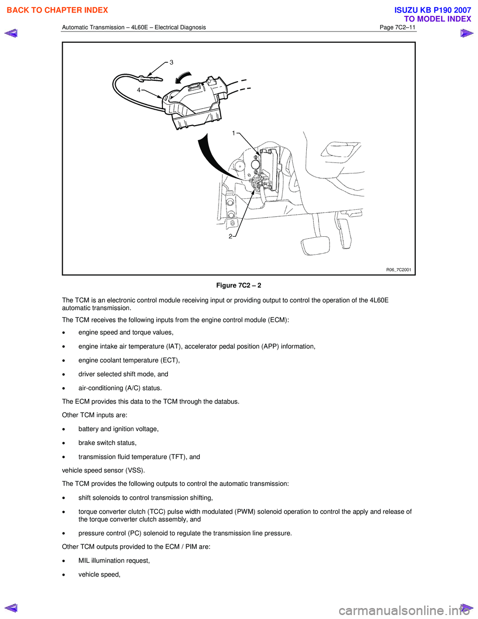
Figure 7C2 – 2
The TCM is an electronic control module receiving input or providing output to control the operation of the 4L60E
automatic transmission.
The TCM receives the following inputs from the engine control module (ECM):
• engine speed and torque values,
• engine intake air temperature (IAT), accelerator pedal position (APP) information,
• engine coolant temperature (ECT),
• driver selected shift mode, and
• air-conditioning (A/C) status.
The ECM provides this data to the TCM through the databus.
Other TCM inputs are:
• battery and ignition voltage,
• brake switch status,
• transmission fluid temperature (TFT), and
vehicle speed sensor (VSS).
The TCM provides the following outputs to control the automatic transmission:
• shift solenoids to control transmission shifting,
• torque converter clutch (TCC) pulse width modulated (PW M) solenoid operation to control the apply and release of
the torque converter clutch assembly, and
• pressure control (PC) solenoid to regulate the transmission line pressure.
Other TCM outputs provided to the ECM / PIM are:
• MIL illumination request,
• vehicle speed,
BACK TO CHAPTER INDEX
TO MODEL INDEX
ISUZU KB P190 2007
Page 3818 of 6020
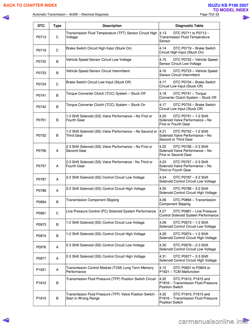
Automatic Transmission – 4L60E – Electrical Diagnosis Page 7C2–32
DTC Type Description Diagnostic Table
P0713 C Transmission Fluid Temperature (TFT) Sensor Circuit High
Voltage 4.13 DTC P0711 to P0713 –
Transmission Fluid Temperature
Sensor
P0719 C Brake Switch Circuit High Input (Stuck On) 4.14 DTC P0719 – Brake Switch
Circuit High Input (Stuck On)
P0722 B Vehicle Speed Sensor Circuit Low Voltage 4.15 DTC P0722 – Vehicle Speed
Sensor Circuit Low Voltage
P0723 B Vehicle Speed Sensor Circuit Intermittent 4.16 DTC P0723 – Vehicle Speed
Sensor Circuit Intermittent
P0724 C Brake Switch Circuit Low Input (Stuck Off) 4.17 DTC P0724 – Brake Switch
Circuit Low Input (Stuck Off)
P0741 B Torque Converter Clutch (TCC) System – Stuck Off 4.18 DTC P0741 – Torque
Converter Clutch System – Stuck Off
P0742 B Torque Converter Clutch (TCC) System – Stuck On 4.17 DTC P0724 – Brake Switch
Circuit Low Input (Stuck Off)
P0751 B 1-2 Shift Solenoid (SS) Valve Performance – No First or
Fourth Gear 4.20 DTC P0751 – 1-2 Shift
Solenoid Valve Performance – No
First or Fourth Gear
P0752 B 1-2 Shift Solenoid (SS) Valve Performance – No Second or
Third Gear 4.21 DTC P0752 – 1-2 Shift
Solenoid Valve Performance – No
Second or Third Gear
P0756 A 2-3 Shift Solenoid (SS) Valve Performance – No First or
Second Gear 4.22 DTC P0756 – 2-3 Shift
Solenoid Valve Performance – No
First or Second Gear
P0757 A 2-3 Shift Solenoid (SS) Valve Performance - No Third or
Fourth Gear 4.23 DTC P0757 – 2-3 Shift
Solenoid Valve Performance – No
Third or Fourth Gear
P0787 A 3-2 Shift Solenoid (SS) Control Circuit Low Voltage 4.24 DTC P0787 – 3-2 Shift
Solenoid Control Circuit Low Voltage
P0788 A 3-2 Shift Solenoid (SS) Control Circuit High Voltage 4.25 DTC P0788 – 3-2 Shift
Solenoid Control Circuit High Voltage
P0894 B Transmission Component Slipping 4.26 DTC P0894 – Transmission
Component Slipping
P0961 C Line Pressure Control (PC) Solenoid System Performance 4.27 DTC P0961 – Line Pressure
Control Solenoid System Performance
P0973 B 1-2 Shift Solenoid (SS) Control Circuit Low Voltage 4.28 DTC P0973 – 1-2 Shift
Solenoid Control Circuit Low Voltage
P0974 B 1-2 Shift Solenoid (SS) Control Circuit High Voltage 4.29 DTC P0974 – 1-2 Shift
Solenoid Control Circuit High Voltage
P0976 A 2-3 Shift Solenoid (SS) Control Circuit Low Voltage 4.30 DTC P0976 – 2-3 Shift
Solenoid Control Circuit Low Voltage
P0977 A 2-3 Shift Solenoid (SS) Control Circuit High Voltage 4.31 DTC P0977 – 2-3 Shift
Solenoid Control Circuit High Voltage
P1621 A Transmission Control Module (TCM) Long Term Memory
Performance 4.12 DTC P0601 to P0604 or
P1621 – TCM Malfunction
P1810 B Transmission Fluid Pressure (TFP) Position Switch Circuit 4.32 DTC P1810, P1815 and
P1816 – Transmission Fluid Pressure
Position Switch
P1815 B Transmission Fluid Pressure (TFP) Valve Position Switch -
Start in W rong Range 4.32 DTC P1810, P1815 and
P1816 – Transmission Fluid Pressure
Position Switch
BACK TO CHAPTER INDEX
TO MODEL INDEX
ISUZU KB P190 2007