2007 ISUZU KB P190 automatic transmission fluid
[x] Cancel search: automatic transmission fluidPage 3818 of 6020
Automatic Transmission – 4L60E – Electrical Diagnosis Page 7C2–32
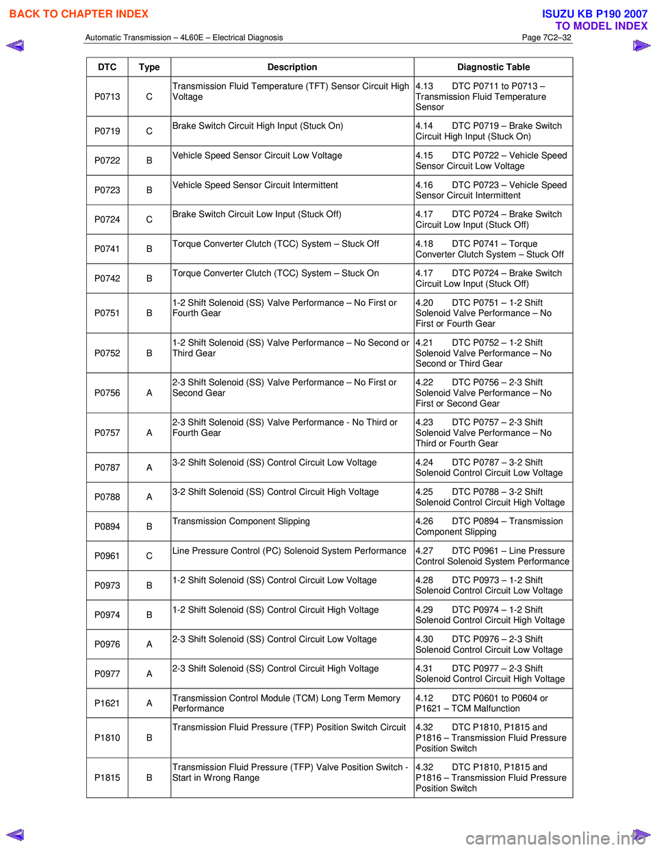
DTC Type Description Diagnostic Table
P0713 C Transmission Fluid Temperature (TFT) Sensor Circuit High
Voltage 4.13 DTC P0711 to P0713 –
Transmission Fluid Temperature
Sensor
P0719 C Brake Switch Circuit High Input (Stuck On) 4.14 DTC P0719 – Brake Switch
Circuit High Input (Stuck On)
P0722 B Vehicle Speed Sensor Circuit Low Voltage 4.15 DTC P0722 – Vehicle Speed
Sensor Circuit Low Voltage
P0723 B Vehicle Speed Sensor Circuit Intermittent 4.16 DTC P0723 – Vehicle Speed
Sensor Circuit Intermittent
P0724 C Brake Switch Circuit Low Input (Stuck Off) 4.17 DTC P0724 – Brake Switch
Circuit Low Input (Stuck Off)
P0741 B Torque Converter Clutch (TCC) System – Stuck Off 4.18 DTC P0741 – Torque
Converter Clutch System – Stuck Off
P0742 B Torque Converter Clutch (TCC) System – Stuck On 4.17 DTC P0724 – Brake Switch
Circuit Low Input (Stuck Off)
P0751 B 1-2 Shift Solenoid (SS) Valve Performance – No First or
Fourth Gear 4.20 DTC P0751 – 1-2 Shift
Solenoid Valve Performance – No
First or Fourth Gear
P0752 B 1-2 Shift Solenoid (SS) Valve Performance – No Second or
Third Gear 4.21 DTC P0752 – 1-2 Shift
Solenoid Valve Performance – No
Second or Third Gear
P0756 A 2-3 Shift Solenoid (SS) Valve Performance – No First or
Second Gear 4.22 DTC P0756 – 2-3 Shift
Solenoid Valve Performance – No
First or Second Gear
P0757 A 2-3 Shift Solenoid (SS) Valve Performance - No Third or
Fourth Gear 4.23 DTC P0757 – 2-3 Shift
Solenoid Valve Performance – No
Third or Fourth Gear
P0787 A 3-2 Shift Solenoid (SS) Control Circuit Low Voltage 4.24 DTC P0787 – 3-2 Shift
Solenoid Control Circuit Low Voltage
P0788 A 3-2 Shift Solenoid (SS) Control Circuit High Voltage 4.25 DTC P0788 – 3-2 Shift
Solenoid Control Circuit High Voltage
P0894 B Transmission Component Slipping 4.26 DTC P0894 – Transmission
Component Slipping
P0961 C Line Pressure Control (PC) Solenoid System Performance 4.27 DTC P0961 – Line Pressure
Control Solenoid System Performance
P0973 B 1-2 Shift Solenoid (SS) Control Circuit Low Voltage 4.28 DTC P0973 – 1-2 Shift
Solenoid Control Circuit Low Voltage
P0974 B 1-2 Shift Solenoid (SS) Control Circuit High Voltage 4.29 DTC P0974 – 1-2 Shift
Solenoid Control Circuit High Voltage
P0976 A 2-3 Shift Solenoid (SS) Control Circuit Low Voltage 4.30 DTC P0976 – 2-3 Shift
Solenoid Control Circuit Low Voltage
P0977 A 2-3 Shift Solenoid (SS) Control Circuit High Voltage 4.31 DTC P0977 – 2-3 Shift
Solenoid Control Circuit High Voltage
P1621 A Transmission Control Module (TCM) Long Term Memory
Performance 4.12 DTC P0601 to P0604 or
P1621 – TCM Malfunction
P1810 B Transmission Fluid Pressure (TFP) Position Switch Circuit 4.32 DTC P1810, P1815 and
P1816 – Transmission Fluid Pressure
Position Switch
P1815 B Transmission Fluid Pressure (TFP) Valve Position Switch -
Start in W rong Range 4.32 DTC P1810, P1815 and
P1816 – Transmission Fluid Pressure
Position Switch
BACK TO CHAPTER INDEX
TO MODEL INDEX
ISUZU KB P190 2007
Page 3819 of 6020
Automatic Transmission – 4L60E – Electrical Diagnosis Page 7C2–33
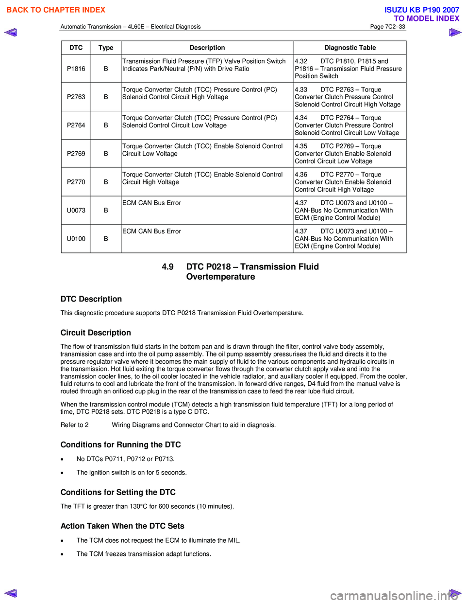
DTC Type Description Diagnostic Table
P1816 B Transmission Fluid Pressure (TFP) Valve Position Switch
Indicates Park/Neutral (P/N) with Drive Ratio 4.32 DTC P1810, P1815 and
P1816 – Transmission Fluid Pressure
Position Switch
P2763 B Torque Converter Clutch (TCC) Pressure Control (PC)
Solenoid Control Circuit High Voltage 4.33 DTC P2763 – Torque
Converter Clutch Pressure Control
Solenoid Control Circuit High Voltage
P2764 B Torque Converter Clutch (TCC) Pressure Control (PC)
Solenoid Control Circuit Low Voltage 4.34 DTC P2764 – Torque
Converter Clutch Pressure Control
Solenoid Control Circuit Low Voltage
P2769 B Torque Converter Clutch (TCC) Enable Solenoid Control
Circuit Low Voltage 4.35 DTC P2769 – Torque
Converter Clutch Enable Solenoid
Control Circuit Low Voltage
P2770 B Torque Converter Clutch (TCC) Enable Solenoid Control
Circuit High Voltage 4.36 DTC P2770 – Torque
Converter Clutch Enable Solenoid
Control Circuit High Voltage
U0073 B ECM CAN Bus Error
4.37 DTC U0073 and U0100 –
CAN-Bus No Communication With
ECM (Engine Control Module)
U0100 B ECM CAN Bus Error
4.37 DTC U0073 and U0100 –
CAN-Bus No Communication With
ECM (Engine Control Module)
4.9 DTC P0218 – Transmission Fluid Overtemperature
DTC Description
This diagnostic procedure supports DTC P0218 Transmission Fluid Overtemperature.
Circuit Description
The flow of transmission fluid starts in the bottom pan and is drawn through the filter, control valve body assembly,
transmission case and into the oil pump assembly. The oil pump assembly pressurises the fluid and directs it to the
pressure regulator valve where it becomes the main supply of fluid to the various components and hydraulic circuits in
the transmission. Hot fluid exiting the torque converter flows through the converter clutch apply valve and into the
transmission cooler lines, to the oil cooler located in the vehicle radiator, and auxiliary cooler if equipped. From the cooler ,
fluid returns to cool and lubricate the front of the transmission. In forward drive ranges, D4 fluid from the manual valve is
routed through an orificed cup plug in the rear of the transmission case to feed the rear lube fluid circuit.
When the transmission control module (TCM) detects a high transmission fluid temperature (TFT) for a long period of
time, DTC P0218 sets. DTC P0218 is a type C DTC.
Refer to 2 W iring Diagrams and Connector Chart to aid in diagnosis.
Conditions for Running the DTC
• No DTCs P0711, P0712 or P0713.
• The ignition switch is on for 5 seconds.
Conditions for Setting the DTC
The TFT is greater than 130°C for 600 seconds (10 minutes).
Action Taken When the DTC Sets
•
The TCM does not request the ECM to illuminate the MIL.
• The TCM freezes transmission adapt functions.
BACK TO CHAPTER INDEX
TO MODEL INDEX
ISUZU KB P190 2007
Page 3820 of 6020
Automatic Transmission – 4L60E – Electrical Diagnosis Page 7C2–34
• The TCM records the operating conditions when the conditions for setting the DTC are met. The TCM stores this
information as Failure Records.
• The TCM stores DTC P0218 in TCM history.
Conditions for Clearing the DTC
• Tech 2 can clear the DTC.
• The TCM clears the DTC from TCM history if the vehicle completes 40 warm-up cycles without a non-emission
related diagnostic fault occurring.
• The TCM cancels the DTC default actions when the fault no longer exists and the DTC passes.
Diagnostic Aids
• Tech 2’s Transmission Fluid Temp. should rise steadily to a normal operating temperature, then stabilise.
• Ask about the customer's driving habits, trailer towing, etc. Trailer towing should occur in D3.
• Refer to Symptoms - Automatic Transmission in 7C3 Automatic Transmission – 4L60E – Hydraulic and Mechanical
Diagnosis.
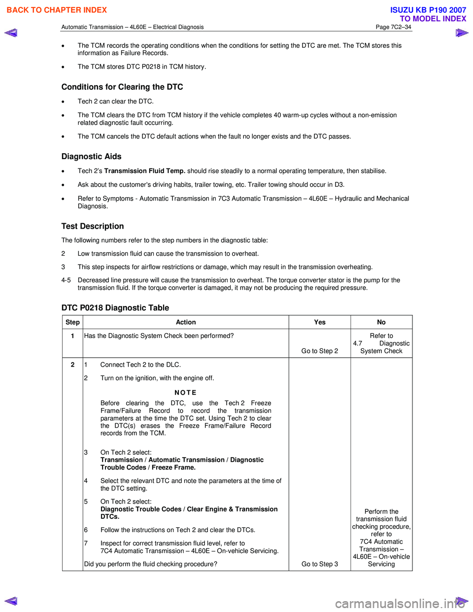
Test Description
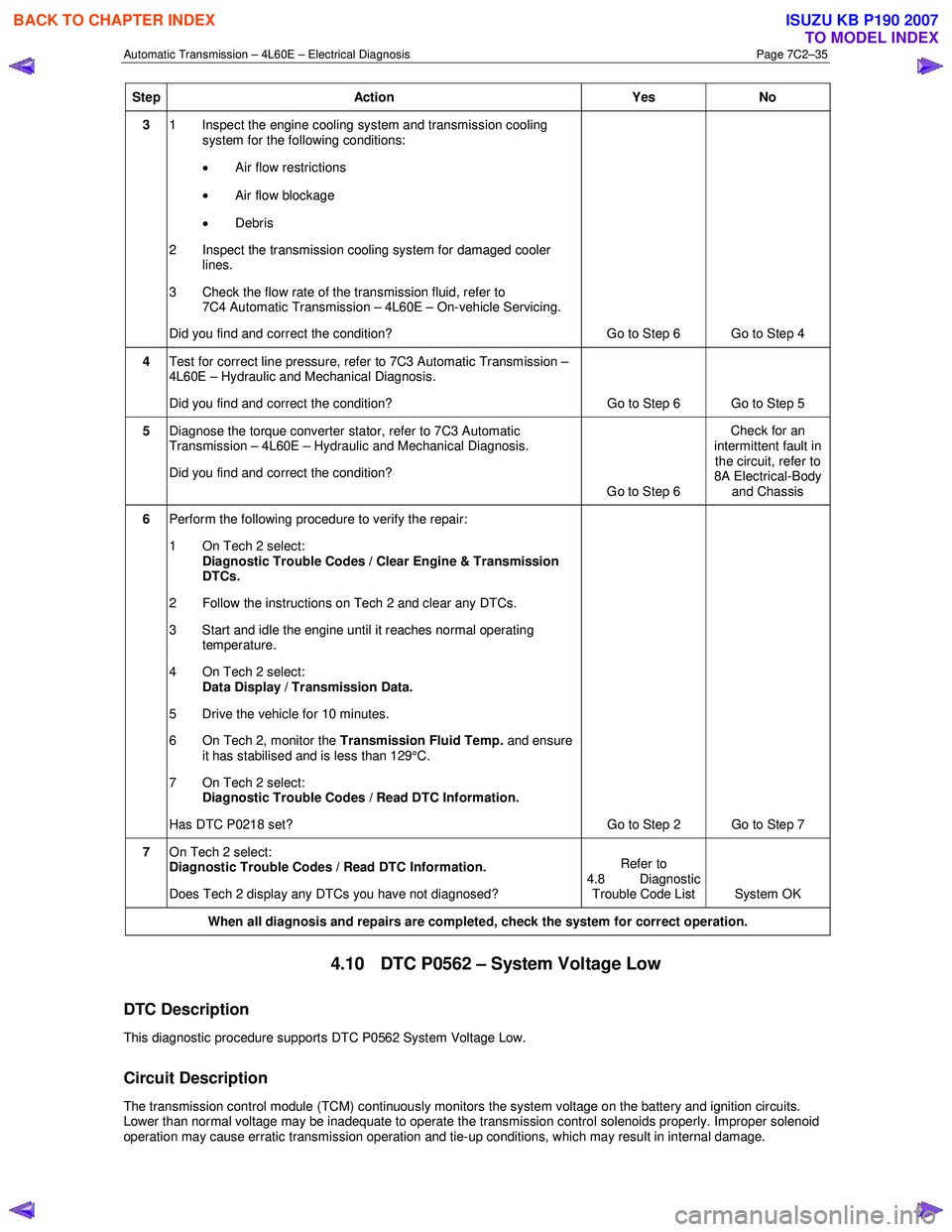
The following numbers refer to the step numbers in the diagnostic table:
2 Low transmission fluid can cause the transmission to overheat.
3 This step inspects for airflow restrictions or damage, which may result in the transmission overheating.
4-5 Decreased line pressure will cause the transmission to overheat. The torque converter stator is the pump for the transmission fluid. If the torque converter is damaged, it may not be producing the required pressure.
DTC P0218 Diagnostic Table
Step Action Yes No
1 Has the Diagnostic System Check been performed?
Go to Step 2 Refer to
4.7 Diagnostic System Check
2 1 Connect Tech 2 to the DLC.
2 Turn on the ignition, with the engine off.
NOTE
Before clearing the DTC, use the Tech 2 Freeze
Frame/Failure Record to record the transmission
parameters at the time the DTC set. Using Tech 2 to clear
the DTC(s) erases the Freeze Frame/Failure Record
records from the TCM.
3 On Tech 2 select: Transmission / Automatic Transmission / Diagnostic
Trouble Codes / Freeze Frame.
4 Select the relevant DTC and note the parameters at the time of the DTC setting.
5 On Tech 2 select:
Diagnostic Trouble Codes / Clear Engine & Transmission
DTCs.
6 Follow the instructions on Tech 2 and clear the DTCs.
7 Inspect for correct transmission fluid level, refer to 7C4 Automatic Transmission – 4L60E – On-vehicle Servicing.
Did you perform the fluid checking procedure? Go to Step 3 Perform the
transmission fluid
checking procedure, refer to
7C4 Automatic
Transmission –
4L60E – On-vehicle Servicing
BACK TO CHAPTER INDEX
TO MODEL INDEX
ISUZU KB P190 2007
Page 3821 of 6020
Automatic Transmission – 4L60E – Electrical Diagnosis Page 7C2–35
Step Action Yes No
3 1 Inspect the engine cooling system and transmission cooling
system for the following conditions:
• Air flow restrictions
• Air flow blockage
• Debris
2 Inspect the transmission cooling system for damaged cooler lines.
3 Check the flow rate of the transmission fluid, refer to 7C4 Automatic Transmission – 4L60E – On-vehicle Servicing.
Did you find and correct the condition? Go to Step 6 Go to Step 4
4 Test for correct line pressure, refer to 7C3 Automatic Transmission –
4L60E – Hydraulic and Mechanical Diagnosis.
Did you find and correct the condition? Go to Step 6 Go to Step 5
5 Diagnose the torque converter stator, refer to 7C3 Automatic
Transmission – 4L60E – Hydraulic and Mechanical Diagnosis.
Did you find and correct the condition? Go to Step 6 Check for an
intermittent fault in the circuit, refer to
8A Electrical-Body
and Chassis
6 Perform the following procedure to verify the repair:
1 On Tech 2 select: Diagnostic Trouble Codes / Clear Engine & Transmission
DTCs.
2 Follow the instructions on Tech 2 and clear any DTCs.
3 Start and idle the engine until it reaches normal operating temperature.
4 On Tech 2 select: Data Display / Transmission Data.
5 Drive the vehicle for 10 minutes.
6 On Tech 2, monitor the Transmission Fluid Temp. and ensure
it has stabilised and is less than 129°C.
7 On Tech 2 select:
Diagnostic Trouble Codes / Read DTC Information.
Has DTC P0218 set? Go to Step 2 Go to Step 7
7 On Tech 2 select:
Diagnostic Trouble Codes / Read DTC Information.
Does Tech 2 display any DTCs you have not diagnosed? Refer to
4.8 Diagnostic Trouble Code List System OK
When all diagnosis and repairs are completed, check the
system for correct operation.
4.10 DTC P0562 – System Voltage Low
DTC Description
This diagnostic procedure supports DTC P0562 System Voltage Low.
Circuit Description
The transmission control module (TCM) continuously monitors the system voltage on the battery and ignition circuits.
Lower than normal voltage may be inadequate to operate the transmission control solenoids properly. Improper solenoid
operation may cause erratic transmission operation and tie-up conditions, which may result in internal damage.
BACK TO CHAPTER INDEX
TO MODEL INDEX
ISUZU KB P190 2007
Page 3829 of 6020
Automatic Transmission – 4L60E – Electrical Diagnosis Page 7C2–43
Step Action Yes No
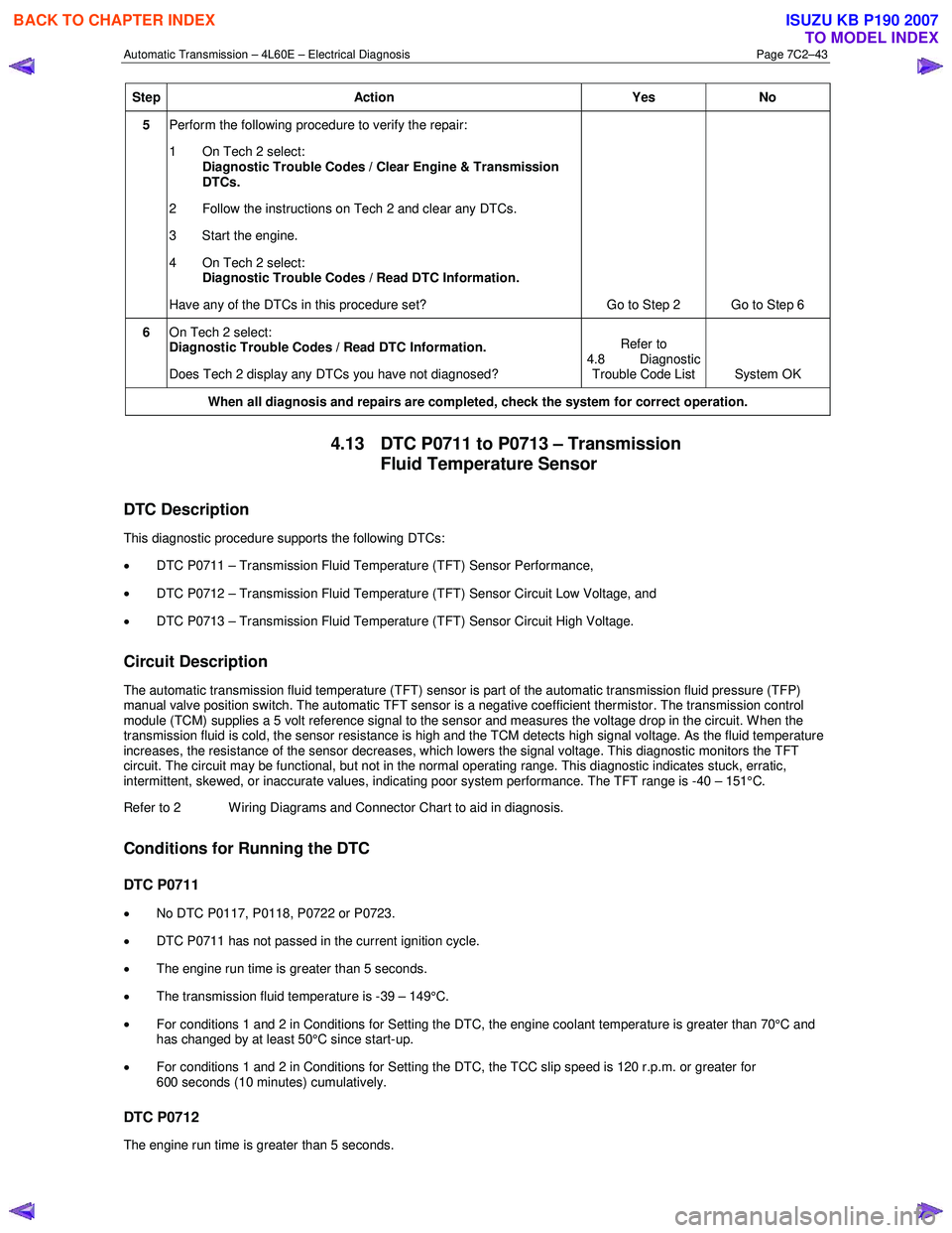
5 Perform the following procedure to verify the repair:
1 On Tech 2 select: Diagnostic Trouble Codes / Clear Engine & Transmission
DTCs.
2 Follow the instructions on Tech 2 and clear any DTCs.
3 Start the engine.
4 On Tech 2 select:
Diagnostic Trouble Codes / Read DTC Information.
Have any of the DTCs in this procedure set? Go to Step 2 Go to Step 6
6 On Tech 2 select:
Diagnostic Trouble Codes / Read DTC Information.
Does Tech 2 display any DTCs you have not diagnosed? Refer to
4.8 Diagnostic Trouble Code List System OK
When all diagnosis and repairs are completed, check the
system for correct operation.
4.13 DTC P0711 to P0713 – Transmission
Fluid Temperature Sensor
DTC Description
This diagnostic procedure supports the following DTCs:
• DTC P0711 – Transmission Fluid Temperature (TFT) Sensor Performance,
• DTC P0712 – Transmission Fluid Temperature (TFT) Sensor Circuit Low Voltage, and
• DTC P0713 – Transmission Fluid Temperature (TFT) Sensor Circuit High Voltage.
Circuit Description
The automatic transmission fluid temperature (TFT) sensor is part of the automatic transmission fluid pressure (TFP)
manual valve position switch. The automatic TFT sensor is a negative coefficient thermistor. The transmission control
module (TCM) supplies a 5 volt reference signal to the sensor and measures the voltage drop in the circuit. W hen the
transmission fluid is cold, the sensor resistance is high and the TCM detects high signal voltage. As the fluid temperature
increases, the resistance of the sensor decreases, which lowers the signal voltage. This diagnostic monitors the TFT
circuit. The circuit may be functional, but not in the normal operating range. This diagnostic indicates stuck, erratic,
intermittent, skewed, or inaccurate values, indicating poor system performance. The TFT range is -40 – 151°C.
Refer to 2 W iring Diagrams and Connector Chart to aid in diagnosis.
Conditions for Running the DTC
DTC P0711
• No DTC P0117, P0118, P0722 or P0723.
• DTC P0711 has not passed in the current ignition cycle.
• The engine run time is greater than 5 seconds.
• The transmission fluid temperature is -39 – 149°C.
• For conditions 1 and 2 in Conditions for Setting the DTC, the engine coolant temperature is greater than 70°C and
has changed by at least 50°C since start-up.
• For conditions 1 and 2 in Conditions for Setting the DTC, the TCC slip speed is 120 r.p.m. or greater for
600 seconds (10 minutes) cumulatively.
DTC P0712
The engine run time is greater than 5 seconds.
BACK TO CHAPTER INDEX
TO MODEL INDEX
ISUZU KB P190 2007
Page 3830 of 6020
Automatic Transmission – 4L60E – Electrical Diagnosis Page 7C2–44
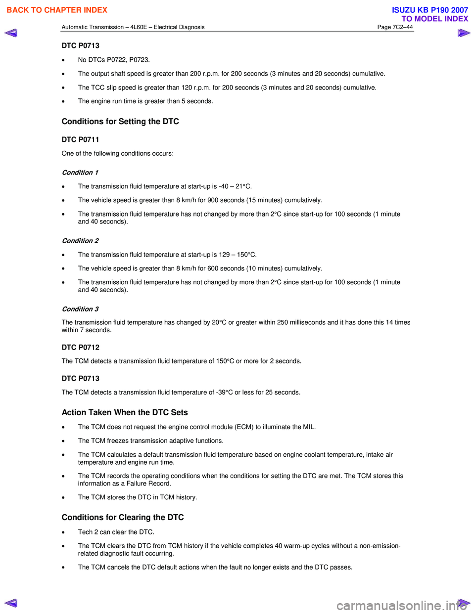
DTC P0713
•
No DTCs P0722, P0723.
• The output shaft speed is greater than 200 r.p.m. for 200 seconds (3 minutes and 20 seconds) cumulative.
• The TCC slip speed is greater than 120 r.p.m. for 200 seconds (3 minutes and 20 seconds) cumulative.
• The engine run time is greater than 5 seconds.
Conditions for Setting the DTC
DTC P0711
One of the following conditions occurs:
Condition 1
•
The transmission fluid temperature at start-up is -40 – 21°C.
• The vehicle speed is greater than 8 km/h for 900 seconds (15 minutes) cumulatively.
• The transmission fluid temperature has not changed by more than 2°C since start-up for 100 seconds (1 minute
and 40 seconds).
Condition 2
• The transmission fluid temperature at start-up is 129 – 150°C.
• The vehicle speed is greater than 8 km/h for 600 seconds (10 minutes) cumulatively.
• The transmission fluid temperature has not changed by more than 2°C since start-up for 100 seconds (1 minute
and 40 seconds).
Condition 3
The transmission fluid temperature has changed by 20°C or greater within 250 milliseconds and it has done this 14 times
within 7 seconds.
DTC P0712
The TCM detects a transmission fluid temperature of 150°C or more for 2 seconds.
DTC P0713
The TCM detects a transmission fluid temperature of -39°C or less for 25 seconds.
Action Taken When the DTC Sets
• The TCM does not request the engine control module (ECM) to illuminate the MIL.
• The TCM freezes transmission adaptive functions.
• The TCM calculates a default transmission fluid temperature based on engine coolant temperature, intake air
temperature and engine run time.
• The TCM records the operating conditions when the conditions for setting the DTC are met. The TCM stores this
information as a Failure Record.
• The TCM stores the DTC in TCM history.
Conditions for Clearing the DTC
•
Tech 2 can clear the DTC.
• The TCM clears the DTC from TCM history if the vehicle completes 40 warm-up cycles without a non-emission-
related diagnostic fault occurring.
• The TCM cancels the DTC default actions when the fault no longer exists and the DTC passes.
BACK TO CHAPTER INDEX
TO MODEL INDEX
ISUZU KB P190 2007
Page 3831 of 6020
Automatic Transmission – 4L60E – Electrical Diagnosis Page 7C2–45
Diagnostic Aids
• Tech 2 displays the transmission fluid temperature in degrees. After the transmission is operating, the fluid
temperature should rise steadily to a normal operating temperature, then stabilise.
• Verify the customer's driving habits, trailer towing, etc. Trailer towing should occur in D3.
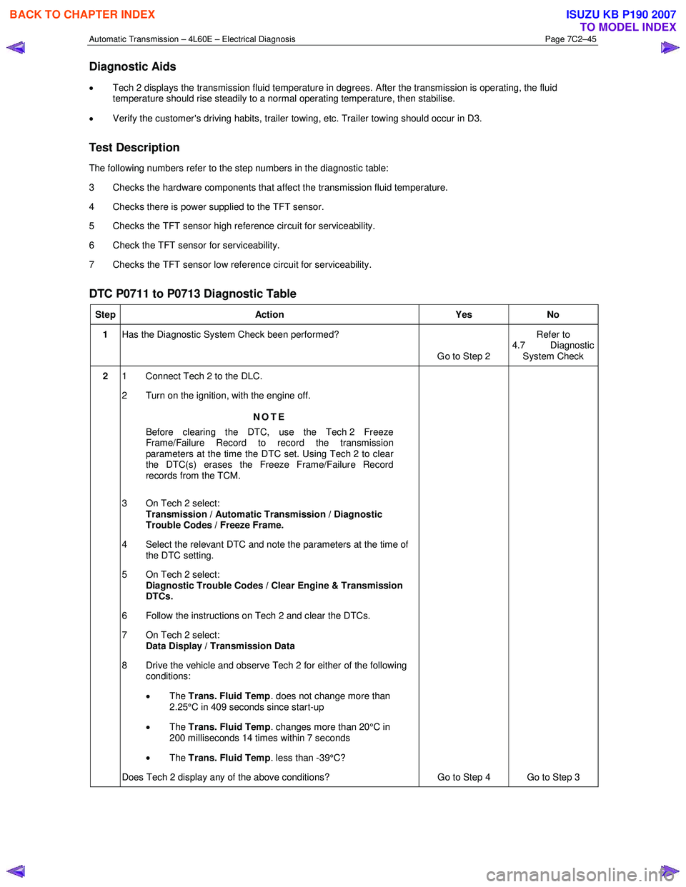
Test Description
The following numbers refer to the step numbers in the diagnostic table:
3 Checks the hardware components that affect the transmission fluid temperature.
4 Checks there is power supplied to the TFT sensor.
5 Checks the TFT sensor high reference circuit for serviceability.
6 Check the TFT sensor for serviceability.
7 Checks the TFT sensor low reference circuit for serviceability.
DTC P0711 to P0713 Diagnostic Table
Step Action Yes No
1 Has the Diagnostic System Check been performed?
Go to Step 2 Refer to
4.7 Diagnostic System Check
2 1 Connect Tech 2 to the DLC.
2 Turn on the ignition, with the engine off.
NOTE
Before clearing the DTC, use the Tech 2 Freeze
Frame/Failure Record to record the transmission
parameters at the time the DTC set. Using Tech 2 to clear
the DTC(s) erases the Freeze Frame/Failure Record
records from the TCM.
3 On Tech 2 select: Transmission / Automatic Transmission / Diagnostic
Trouble Codes / Freeze Frame.
4 Select the relevant DTC and note the parameters at the time of the DTC setting.
5 On Tech 2 select:
Diagnostic Trouble Codes / Clear Engine & Transmission
DTCs.
6 Follow the instructions on Tech 2 and clear the DTCs.
7 On Tech 2 select: Data Display / Transmission Data
8 Drive the vehicle and observe Tech 2 for either of the following conditions:
• The Trans. Fluid Temp . does not change more than
2.25°C in 409 seconds since start-up
• The Trans. Fluid Temp . changes more than 20°C in
200 milliseconds 14 times within 7 seconds
• The Trans. Fluid Temp . less than -39°C?
Does Tech 2 display any of the above conditions? Go to Step 4 Go to Step 3
BACK TO CHAPTER INDEX
TO MODEL INDEX
ISUZU KB P190 2007
Page 3832 of 6020
Automatic Transmission – 4L60E – Electrical Diagnosis Page 7C2–46
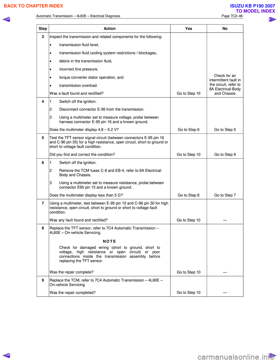
Step Action Yes No
3 Inspect the transmission and related components for the following:
• transmission fluid level,
• transmission fluid cooling system restrictions / blockages,
• debris in the transmission fluid,
• incorrect line pressure,
• torque converter stator operation, and
• transmission overload.
W as a fault found and rectified? Go to Step 10 Check for an
intermittent fault in
the circuit, refer to
8A Electrical-Body and Chassis
4 1 Switch off the ignition.
2 Disconnect connector E-95 from the transmission.
3 Using a multimeter set to measure voltage, probe between harness connector E-95 pin 16 and a known ground.
Does the multimeter display 4.8 – 5.2 V? Go to Step 6 Go to Step 5
5 Test the TFT sensor signal circuit (between connectors E-95 pin 16
and C-96 pin 35) for a high resistance, open circuit, short to ground or
short to voltage fault condition.
Did you find and correct the condition? Go to Step 10 Go to Step 9
6 1 Switch off the ignition.
2 Remove the TCM fuses C-8 and EB-4, refer to 8A Electrical- Body and Chassis.
3 Using a multimeter set to measure resistance, probe between connector E95 pin 15 and a known ground.
Does the multimeter display less than 5 Ω? Go to Step 8 Go to Step 7
7 Using a multimeter, test between E-95 pin 15 and C-96 pin 30 for high
resistance, open circuit, short to ground or short to voltage fault
condition.
W as any fault found and rectified? Go to Step 10 —
8 Replace the TFT sensor, refer to 7C4 Automatic Transmission –
4L60E – On-vehicle Servicing.
NOTE
Check for damaged wiring (short to ground, short to
voltage, high resistance or open circuit) or poor
connections inside the transmission assembly before
replacing the TFT sensor.
Was the repair complete? Go to Step 10 —
9 Replace the TCM, refer to 7C4 Automatic Transmission – 4L60E –
On-vehicle Servicing
Was the repair completed? Go to Step 10
—
BACK TO CHAPTER INDEX
TO MODEL INDEX
ISUZU KB P190 2007