2007 ISUZU KB P190 automatic transmission fluid
[x] Cancel search: automatic transmission fluidPage 3776 of 6020
Automatic Transmission – 4L60E – General Information Page 7C1–16
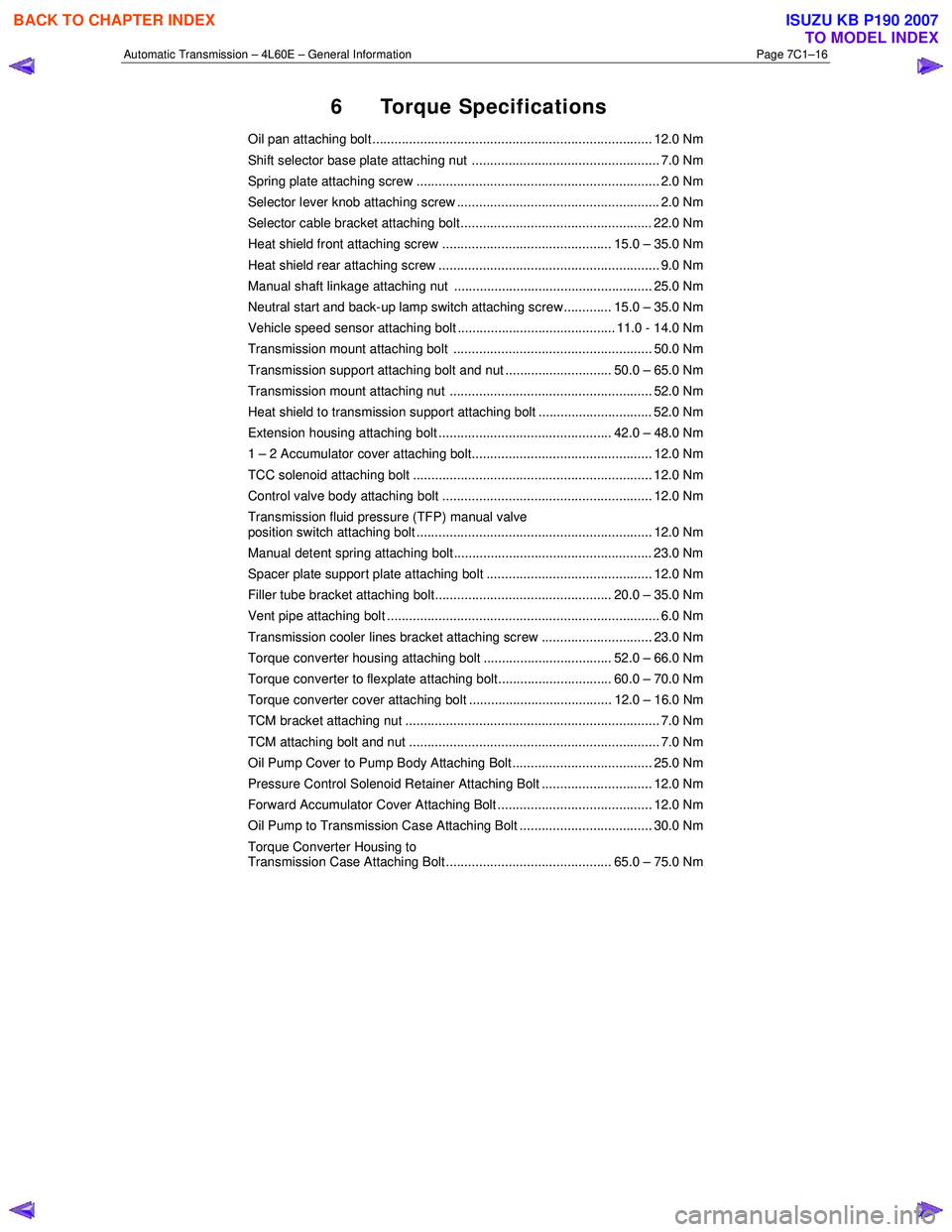
6 Torque Specifications
Oil pan attaching bolt ............................................................................ 12.0 Nm
Shift selector base plate attaching nut ................................................... 7.0 Nm
Spring plate attaching screw .................................................................. 2.0 Nm
Selector lever knob attaching screw ....................................................... 2.0 Nm
Selector cable bracket attaching bolt.................................................... 22.0 Nm
Heat shield front attaching screw .............................................. 15.0 – 35.0 Nm
Heat shield rear attaching screw ............................................................ 9.0 Nm
Manual shaft linkage attaching nut ...................................................... 25.0 Nm
Neutral start and back-up lamp switch attaching screw............. 15.0 – 35.0 Nm
Vehicle speed sensor attaching bolt ........................................... 11.0 - 14.0 Nm
Transmission mount attaching bolt ...................................................... 50.0 Nm
Transmission support attaching bolt and nut ............................. 50.0 – 65.0 Nm
Transmission mount attaching nut ....................................................... 52.0 Nm
Heat shield to transmission support attaching bolt ............................... 52.0 Nm
Extension housing attaching bolt ............................................... 42.0 – 48.0 Nm
1 – 2 Accumulator cover attaching bolt................................................. 12.0 Nm
TCC solenoid attaching bolt ................................................................. 12.0 Nm
Control valve body attaching bolt ......................................................... 12.0 Nm
Transmission fluid pressure (TFP) manual valve
position switch attaching bolt ................................................................ 12.0 Nm
Manual detent spring attaching bolt ...................................................... 23.0 Nm
Spacer plate support plate attaching bolt ............................................. 12.0 Nm
Filler tube bracket attaching bolt................................................ 20.0 – 35.0 Nm
Vent pipe attaching bolt .......................................................................... 6.0 Nm
Transmission cooler lines bracket attaching screw .............................. 23.0 Nm
Torque converter housing attaching bolt ................................... 52.0 – 66.0 Nm
Torque converter to flexplate attaching bolt............................... 60.0 – 70.0 Nm
Torque converter cover attaching bolt ....................................... 12.0 – 16.0 Nm
TCM bracket attaching nut ..................................................................... 7.0 Nm
TCM attaching bolt and nut .................................................................... 7.0 Nm
Oil Pump Cover to Pump Body Attaching Bolt...................................... 25.0 Nm
Pressure Control Solenoid Retainer Attaching Bolt .............................. 12.0 Nm
Forward Accumulator Cover Attaching Bolt .......................................... 12.0 Nm
Oil Pump to Transmission Case Attaching Bolt .................................... 30.0 Nm
Torque Converter Housing to
Transmission Case Attaching Bolt............................................. 65.0 – 75.0 Nm
BACK TO CHAPTER INDEX
TO MODEL INDEX
ISUZU KB P190 2007
Page 3777 of 6020
Automatic Transmission – 4L60E – General Information Page 7C1–17
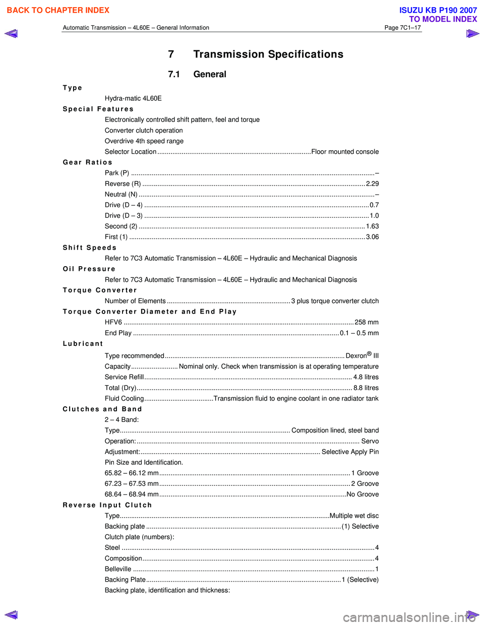
7 Transmission Specifications
7.1 General
Type
Hydra-matic 4L60E
Special Features
Electronically controlled shift pattern, feel and torque
Converter clutch operation
Overdrive 4th speed range
Selector Location ..................................................................................Floor mounted console
Gear Ratios Park (P) ....................................................................................................................... ........... –
Reverse (R) .................................................................................................................... ... 2.29
Neutral (N) .............................................................................................................................. –
Drive (D – 4) .................................................................................................................. ...... 0.7
Drive (D – 3) .................................................................................................................. ...... 1.0
Second (2) ......................................................................................................................... 1.63
First (1) ...................................................................................................................... ........ 3.06
Shift Speeds Refer to 7C3 Automatic Transmission – 4L60E – Hydraulic and Mechanical Diagnosis
Oil Pressure
Refer to 7C3 Automatic Transmission – 4L60E – Hydraulic and Mechanical Diagnosis
Torque Converter
Number of Elements .................................................................. 3 plus torque converter clutch
Torque Converter Diameter and End Play
HFV6 ........................................................................................................................... 258 mm
End Play .............................................................................................................. 0.1 – 0.5 mm
Lubricant
Type recommended ................................................................................................ Dexron
® III
Capacity......................... Nominal only. Check when transmission is at operating temperature
Service Refill ............................................................................................................... 4. 8 litres
Total (Dry)................................................................................................................... 8 .8 litres
Fluid Cooling.....................................Transmission fluid to engine coolant in one radiator tank
Clutches and Band 2 – 4 Band:
Type........................................................................................... Composition lined, steel band
Operation: ..................................................................................................................... .. Servo
Adjustment: ................................................................................................ Selective Apply Pin
Pin Size and Identification.
65.82 – 66.12 mm ...................................................................................................... 1 Groove
67.23 – 67.53 mm ...................................................................................................... 2 Groove
68.64 – 68.94 mm ....................................................................................................No Groove
Reverse Input Clutch Type................................................................................................................Multiple we t disc
Backing plate ........................................................................................................ (1) Select ive
Clutch plate (numbers):
Steel ....................................................................................................................................... 4
Composition............................................................................................................................ 4
Belleville ..................................................................................................................... ............ 1
Backing Plate ........................................................................................................ 1 (Selecti ve)
Backing plate, identification and thickness:
BACK TO CHAPTER INDEX
TO MODEL INDEX
ISUZU KB P190 2007
Page 3784 of 6020
Automatic Transmission – 4L60E – General Information Page 7C1–24
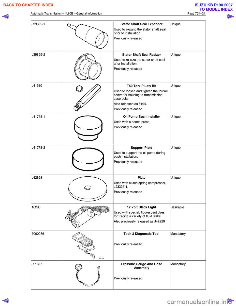
J39855-1
Stator Shaft Seal Expander
Used to expand the stator shaft seal
prior to installation.
Previously released Unique
J39855-2
Stator Shaft Seal Resizer
Used to re-size the stator shaft seal
after installation.
Previously released Unique
J41510
T50 Torx Plus
Bit
Used to loosen and tighten the torque
converter housing to transmission
case bolts.
Also released as 6194.
Previously released Unique
J41778-1
Oil Pump Bush Installer
Used with a bench press.
Previously released Unique
J41778-2
Support Plate
Used to support the oil pump during
bush installation.
Previously released Unique
J42628
Plate
Used with clutch spring compressor,
J23327-1.
Previously released Unique
16296 12 Volt Black Light
Used with special, fluorescent dyes
for tracing a variety of fluid leaks.
Also previously released as J42220 Desirable
70000861
Tech 2 Diagnostic Tool
Previously released Mandatory
J21867
Pressure Gauge And Hose
Assembly
Previously released Mandatory
BACK TO CHAPTER INDEX
TO MODEL INDEX
ISUZU KB P190 2007
Page 3785 of 6020
Automatic Transmission – 4L60E – General Information Page 7C1–25
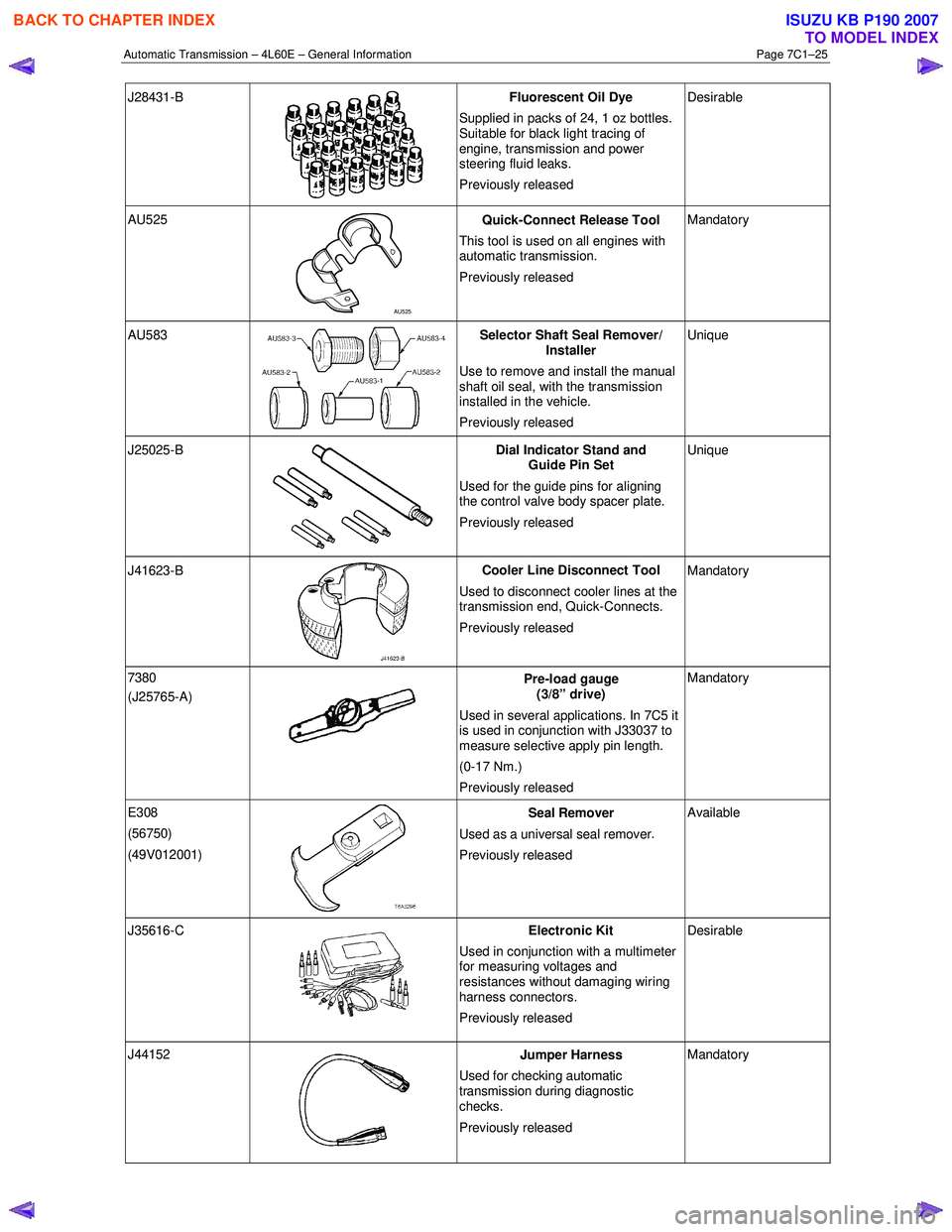
J28431-B
Fluorescent Oil Dye
Supplied in packs of 24, 1 oz bottles.
Suitable for black light tracing of
engine, transmission and power
steering fluid leaks.
Previously released Desirable
AU525
AU525 Quick-Connect Release Tool
This tool is used on all engines with
automatic transmission.
Previously released Mandatory
AU583 Selector Shaft Seal Remover/
Installer
Use to remove and install the manual
shaft oil seal, with the transmission
installed in the vehicle.
Previously released Unique
J25025-B
Dial Indicator Stand and
Guide Pin Set
Used for the guide pins for aligning
the control valve body spacer plate.
Previously released Unique
J41623-B
Cooler Line Disconnect Tool
Used to disconnect cooler lines at the
transmission end, Quick-Connects.
Previously released Mandatory
7380
(J25765-A)
Pre-load gauge
(3/8” drive)
Used in several applications. In 7C5 it
is used in conjunction with J33037 to
measure selective apply pin length.
(0-17 Nm.)
Previously released Mandatory
E308
(56750)
(49V012001)
Seal Remover
Used as a universal seal remover .
Previously released Available
J35616-C
Electronic Kit
Used in conjunction with a multimeter
for measuring voltages and
resistances without damaging wiring
harness connectors.
Previously released Desirable
J44152
Jumper Harness
Used for checking automatic
transmission during diagnostic
checks.
Previously released Mandatory
BACK TO CHAPTER INDEX
TO MODEL INDEX
ISUZU KB P190 2007
Page 3788 of 6020
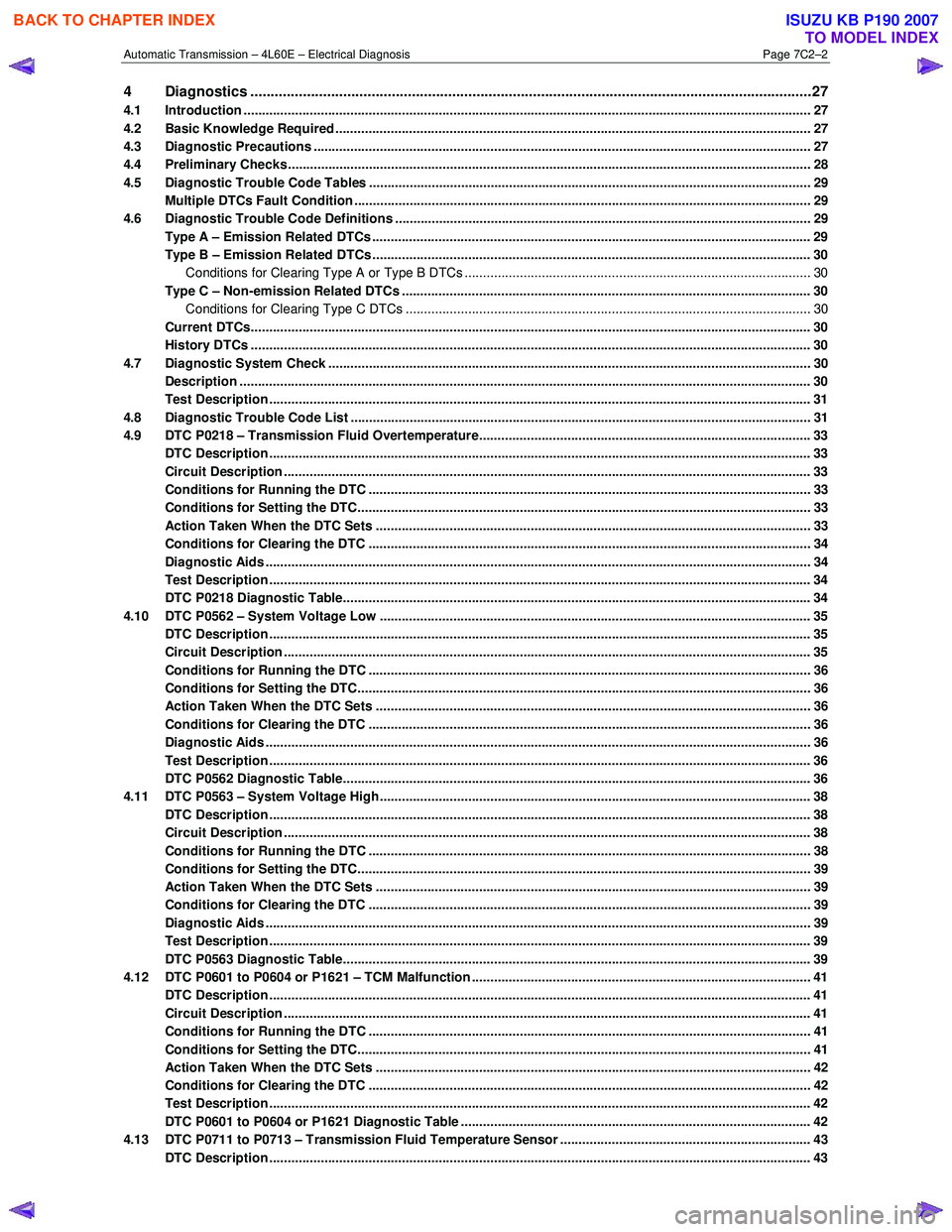
Automatic Transmission – 4L60E – Electrical Diagnosis Page 7C2–2
4 Diagnostics ...........................................................................................................................................27
4.1 Introduction ................................................................................................................... ....................................... 27
4.2 Basic Knowledge Required ....................................................................................................... .......................... 27
4.3 Diagnostic Precautions ....................................................................................................................................... 27
4.4 Preliminary Checks.............................................................................................................................................. 28
4.5 Diagnostic Trouble Code Tables ................................................................................................. ....................... 29
Multiple DTCs Fault Condition ............................................................................................................................ 29
4.6 Diagnostic Trouble Code Definitions ............................................................................................ ..................... 29
Type A – Emission Related DTCs ....................................................................................................................... 29
Type B – Emission Related DTCs ....................................................................................................................... 30
Conditions for Clearing Type A or Type B DTCs .................................................................................. ............ 30
Type C – Non-emission Related DTCs ............................................................................................................... 30
Conditions for Clearing Type C DTCs .............................................................................................................. 30
Current DTCs........................................................................................................................................................ 30
History DTCs ........................................................................................................................................................ 30
4.7 Diagnostic System Check ........................................................................................................ ........................... 30
Description ........................................................................................................................................................... 30
Test Description ................................................................................................................................................... 31
4.8 Diagnostic Trouble Code List ................................................................................................... .......................... 31
4.9 DTC P0218 – Transmission Fluid Overtemperature................................................................................. ......... 33
DTC Description ................................................................................................................................................... 33
Circuit Description ............................................................................................................................................... 33
Conditions for Running the DTC ................................................................................................. ....................... 33
Conditions for Setting the DTC........................................................................................................................... 33
Action Taken When the DTC Sets ................................................................................................. ..................... 33
Conditions for Clearing the DTC ........................................................................................................................ 34
Diagnostic Aids .................................................................................................................................................... 34
Test Description ................................................................................................................................................... 34
DTC P0218 Diagnostic Table..................................................................................................... .......................... 34
4.10 DTC P0562 – System Voltage Low ................................................................................................. .................... 35
DTC Description ................................................................................................................................................... 35
Circuit Description ............................................................................................................................................... 35
Conditions for Running the DTC ................................................................................................. ....................... 36
Conditions for Setting the DTC........................................................................................................................... 36
Action Taken When the DTC Sets ................................................................................................. ..................... 36
Conditions for Clearing the DTC ........................................................................................................................ 36
Diagnostic Aids .................................................................................................................................................... 36
Test Description ................................................................................................................................................... 36
DTC P0562 Diagnostic Table..................................................................................................... .......................... 36
4.11 DTC P0563 – System Voltage High................................................................................................ ..................... 38
DTC Description ................................................................................................................................................... 38
Circuit Description ............................................................................................................................................... 38
Conditions for Running the DTC ................................................................................................. ....................... 38
Conditions for Setting the DTC........................................................................................................................... 39
Action Taken When the DTC Sets ................................................................................................. ..................... 39
Conditions for Clearing the DTC ........................................................................................................................ 39
Diagnostic Aids .................................................................................................................................................... 39
Test Description ................................................................................................................................................... 39
DTC P0563 Diagnostic Table..................................................................................................... .......................... 39
4.12 DTC P0601 to P0604 or P1621 – TCM Malfunction .................................................................................. .......... 41
DTC Description ................................................................................................................................................... 41
Circuit Description ............................................................................................................................................... 41
Conditions for Running the DTC ................................................................................................. ....................... 41
Conditions for Setting the DTC........................................................................................................................... 41
Action Taken When the DTC Sets ................................................................................................. ..................... 42
Conditions for Clearing the DTC ........................................................................................................................ 42
Test Description ................................................................................................................................................... 42
DTC P0601 to P0604 or P1621 Diagnostic Table ................................................................................... ............ 42
4.13 DTC P0711 to P0713 – Transmission Fluid Temperature Sensor .................................................................... 4 3
DTC Description ................................................................................................................................................... 43
BACK TO CHAPTER INDEX
TO MODEL INDEX
ISUZU KB P190 2007
Page 3792 of 6020
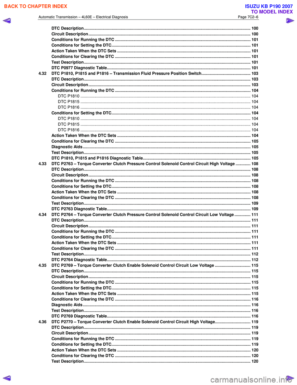
Automatic Transmission – 4L60E – Electrical Diagnosis Page 7C2–6
DTC Description ................................................................................................................................................. 100
Circuit Description ............................................................................................................................................. 100
Conditions for Running the DTC ................................................................................................. ..................... 101
Conditions for Setting the DTC......................................................................................................................... 101
Action Taken When the DTC Sets ................................................................................................. ................... 101
Conditions for Clearing the DTC ...................................................................................................................... 101
Test Description ................................................................................................................................................. 101
DTC P0977 Diagnostic Table..................................................................................................... ........................ 101
4.32 DTC P1810, P1815 and P1816 – Transmission Fluid Pressure Position Switch........................................... 103
DTC Description ................................................................................................................................................. 103
Circuit Description ............................................................................................................................................. 103
Conditions for Running the DTC ................................................................................................. ..................... 104
DTC P1810 .................................................................................................................................................... 104
DTC P1815 .................................................................................................................................................... 104
DTC P1816 .................................................................................................................................................... 104
Conditions for Setting the DTC................................................................................................. ........................ 104
DTC P1810 .................................................................................................................................................... 104
DTC P1815 .................................................................................................................................................... 104
DTC P1816 .................................................................................................................................................... 104
Action Taken When the DTC Sets ................................................................................................. ................... 104
Conditions for Clearing the DTC ...................................................................................................................... 105
Diagnostic Aids .................................................................................................................................................. 105
Test Description ................................................................................................................................................. 105
DTC P1810, P1815 and P1816 Diagnostic Table.................................................................................... .......... 105
4.33 DTC P2763 – Torque Converter Clutch Pressure Control Solenoid Control Circuit High Voltage ............. 108
DTC Description ................................................................................................................................................. 108
Circuit Description ............................................................................................................................................. 108
Conditions for Running the DTC ................................................................................................. ..................... 108
Conditions for Setting the DTC......................................................................................................................... 108
Action Taken When the DTC Sets ................................................................................................. ................... 108
Conditions for Clearing the DTC ...................................................................................................................... 108
Test Description ................................................................................................................................................. 109
DTC P2763 Diagnostic Table..................................................................................................... ........................ 109
4.34 DTC P2764 – Torque Converter Clutch Pressure Control Solenoid Control Circuit Low Voltage .............. 111
DTC Description ................................................................................................................................................. 111
Circuit Description ............................................................................................................................................. 111
Conditions for Running the DTC ................................................................................................. ..................... 111
Conditions for Setting the DTC......................................................................................................................... 111
Action Taken When the DTC Sets ................................................................................................. ................... 111
Conditions for Clearing the DTC ...................................................................................................................... 111
Test Description ................................................................................................................................................. 112
DTC P2764 Diagnostic Table..................................................................................................... ........................ 112
4.35 DTC P2769 – Torque Converter Clutch Enable Solenoid Control Circuit Low Voltage ............................... 115
DTC Description ................................................................................................................................................. 115
Circuit Description ............................................................................................................................................. 115
Conditions for Running the DTC ................................................................................................. ..................... 115
Conditions for Setting the DTC......................................................................................................................... 115
Action Taken When the DTC Sets ................................................................................................. ................... 115
Conditions for Clearing the DTC ...................................................................................................................... 116
Diagnostic Aids .................................................................................................................................................. 116
Test Description ................................................................................................................................................. 116
DTC P2769 Diagnostic Table..................................................................................................... ........................ 116
4.36 DTC P2770 – Torque Converter Clutch Enable Solenoid Control Circuit High Voltage............................... 119
DTC Description ................................................................................................................................................. 119
Circuit Description ............................................................................................................................................. 119
Conditions for Running the DTC ................................................................................................. ..................... 119
Conditions for Setting the DTC......................................................................................................................... 119
Action Taken When the DTC Sets ................................................................................................. ................... 120
Conditions for Clearing the DTC ...................................................................................................................... 120
Test Description ................................................................................................................................................. 120
BACK TO CHAPTER INDEX
TO MODEL INDEX
ISUZU KB P190 2007
Page 3793 of 6020
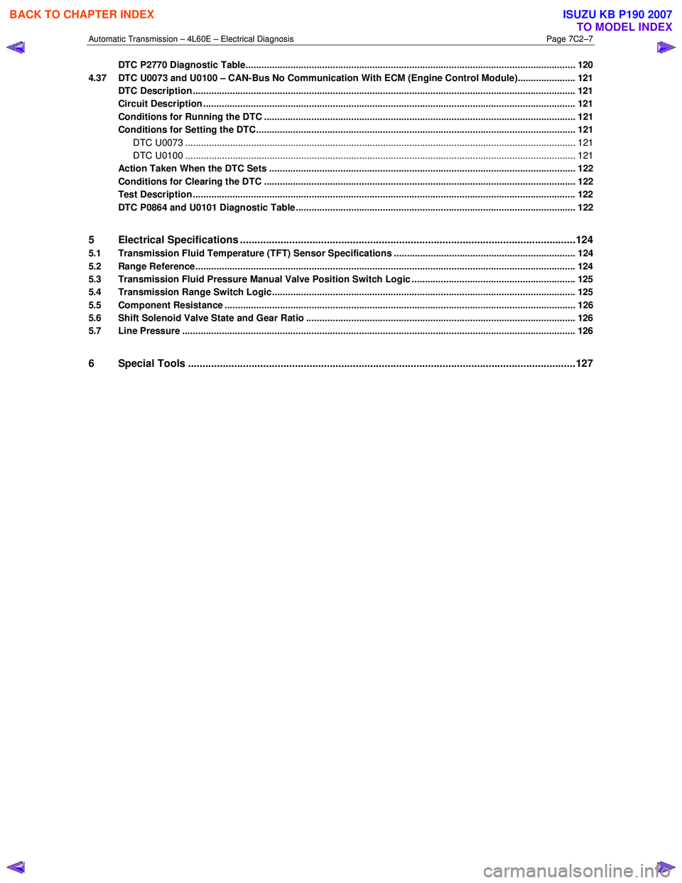
Automatic Transmission – 4L60E – Electrical Diagnosis Page 7C2–7
DTC P2770 Diagnostic Table............................................................................................................................. 120
4.37 DTC U0073 and U0100 – CAN-Bus No Communication With ECM (Engine Control Module)...................... 121
DTC Description ................................................................................................................................................. 121
Circuit Description ............................................................................................................................................. 121
Conditions for Running the DTC ................................................................................................. ..................... 121
Conditions for Setting the DTC......................................................................................................................... 121
DTC U0073 .................................................................................................................................................... 121
DTC U0100 .................................................................................................................................................... 121
Action Taken When the DTC Sets ................................................................................................. ................... 122
Conditions for Clearing the DTC ...................................................................................................................... 122
Test Description ................................................................................................................................................. 122
DTC P0864 and U0101 Diagnostic Table........................................................................................... ............... 122
5 Electrical Specifications ....................................................................................................................124
5.1 Transmission Fluid Temperature (TFT) Sensor Specifications ..................................................................... 124
5.2 Range Reference................................................................................................................................................ 124
5.3 Transmission Fluid Pressure Manual Valve Position Switch Logic .............................................................. 125
5.4 Transmission Range Switch Logic................................................................................................................... 125
5.5 Component Resistance ..................................................................................................................................... 126
5.6 Shift Solenoid Valve State and Gear Ratio ...................................................................................................... 126
5.7 Line Pressure ..................................................................................................................................................... 126
6 Special Tools ......................................................................................................................................127
BACK TO CHAPTER INDEX
TO MODEL INDEX
ISUZU KB P190 2007
Page 3794 of 6020
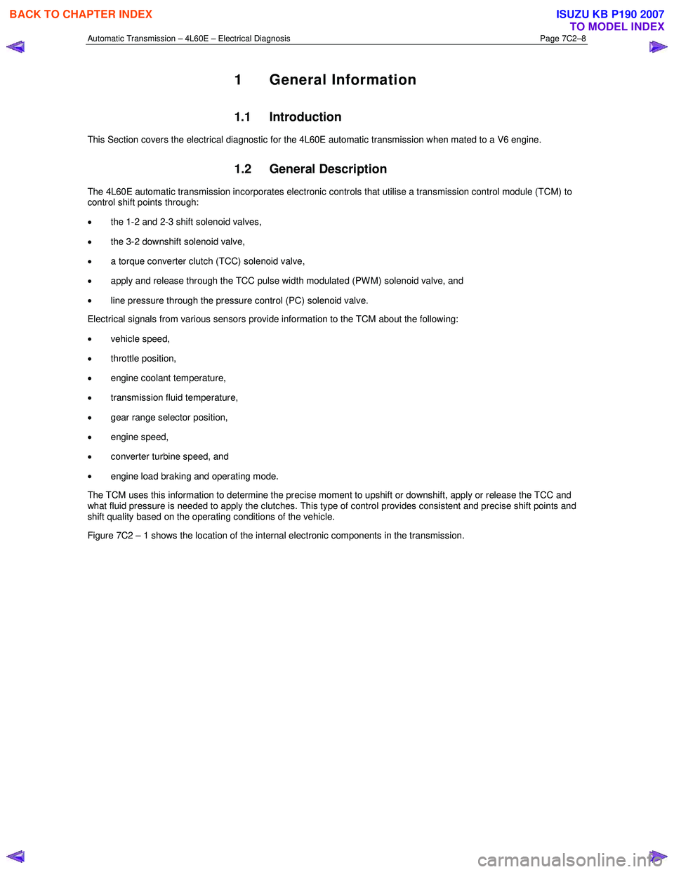
Automatic Transmission – 4L60E – Electrical Diagnosis Page 7C2–8
1 General Information
1.1 Introduction
This Section covers the electrical diagnostic for the 4L60E automatic transmission when mated to a V6 engine.
1.2 General Description
The 4L60E automatic transmission incorporates electronic controls that utilise a transmission control module (TCM) to
control shift points through:
• the 1-2 and 2-3 shift solenoid valves,
• the 3-2 downshift solenoid valve,
• a torque converter clutch (TCC) solenoid valve,
• apply and release through the TCC pulse width modulated (PW M) solenoid valve, and
• line pressure through the pressure control (PC) solenoid valve.
Electrical signals from various sensors provide information to the TCM about the following:
• vehicle speed,
• throttle position,
• engine coolant temperature,
• transmission fluid temperature,
• gear range selector position,
• engine speed,
• converter turbine speed, and
• engine load braking and operating mode.
The TCM uses this information to determine the precise moment to upshift or downshift, apply or release the TCC and
what fluid pressure is needed to apply the clutches. This type of control provides consistent and precise shift points and
shift quality based on the operating conditions of the vehicle.
Figure 7C2 – 1 shows the location of the internal electronic components in the transmission.
BACK TO CHAPTER INDEX
TO MODEL INDEX
ISUZU KB P190 2007