2007 ISUZU KB P190 service
[x] Cancel search: servicePage 3379 of 6020
Engine Management – V6 – Diagnostics Page 6C1-2–101
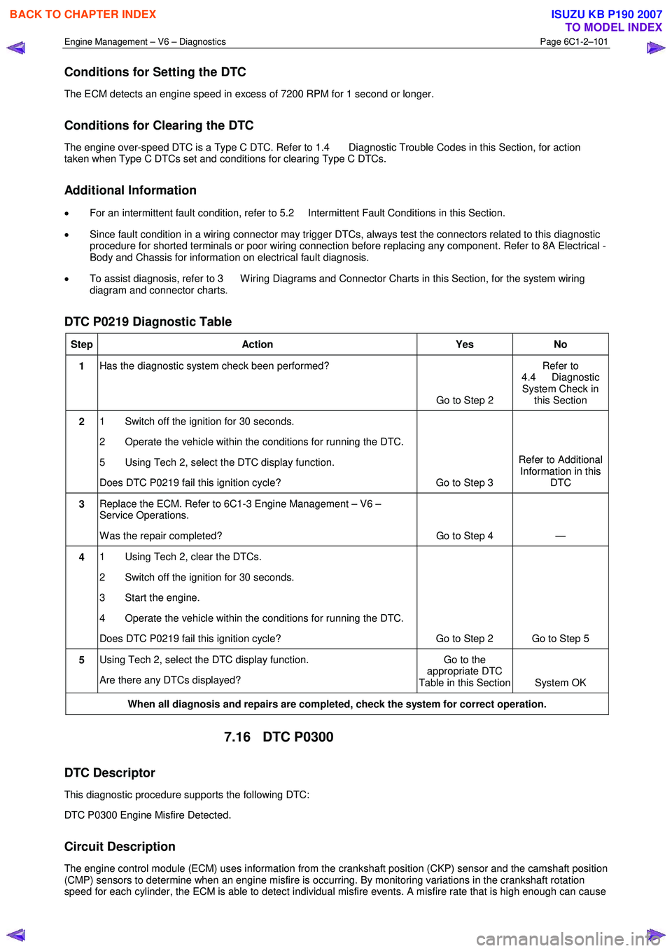
Conditions for Setting the DTC
The ECM detects an engine speed in excess of 7200 RPM for 1 second or longer.
Conditions for Clearing the DTC
The engine over-speed DTC is a Type C DTC. Refer to 1.4 Diagnostic Trouble Codes in this Section, for action
taken when Type C DTCs set and conditions for clearing Type C DTCs.
Additional Information
• For an intermittent fault condition, refer to 5.2 Intermittent Fault Conditions in this Section.
• Since fault condition in a wiring connector may trigger DTCs, always test the connectors related to this diagnostic
procedure for shorted terminals or poor wiring connection before replacing any component. Refer to 8A Electrical -
Body and Chassis for information on electrical fault diagnosis.
• To assist diagnosis, refer to 3 W iring Diagrams and Connector Charts in this Section, for the system wiring
diagram and connector charts.
DTC P0219 Diagnostic Table
Step Action Yes No
1 Has the diagnostic system check been performed?
Go to Step 2 Refer to
4.4 Diagnostic System Check in this Section
2 1 Switch off the ignition for 30 seconds.
2 Operate the vehicle within the conditions for running the DTC.
5 Using Tech 2, select the DTC display function.
Does DTC P0219 fail this ignition cycle? Go to Step 3 Refer to Additional
Information in this DTC
3 Replace the ECM. Refer to 6C1-3 Engine Management – V6 –
Service Operations.
W as the repair completed? Go to Step 4 —
4 1 Using Tech 2, clear the DTCs.
2 Switch off the ignition for 30 seconds.
3 Start the engine.
4 Operate the vehicle within the conditions for running the DTC.
Does DTC P0219 fail this ignition cycle? Go to Step 2 Go to Step 5
5 Using Tech 2, select the DTC display function.
Are there any DTCs displayed? Go to the
appropriate DTC
Table in this Section System OK
When all diagnosis and repairs are completed, check the system for correct operation.
7.16 DTC P0300
DTC Descriptor
This diagnostic procedure supports the following DTC:
DTC P0300 Engine Misfire Detected.
Circuit Description
The engine control module (ECM) uses information from the crankshaft position (CKP) sensor and the camshaft position
(CMP) sensors to determine when an engine misfire is occurring. By monitoring variations in the crankshaft rotation
speed for each cylinder, the ECM is able to detect individual misfire events. A misfire rate that is high enough can cause
BACK TO CHAPTER INDEX
TO MODEL INDEX
ISUZU KB P190 2007
Page 3382 of 6020

Engine Management – V6 – Diagnostics Page 6C1-2–104
Step Action Yes No
9 1 Inspect or test for the following conditions:
• Inspect the vacuum hoses for splits, kinks, and proper
connections.
• Inspect the throttle body and the intake manifold for
vacuum leaks.
• Inspect the crankcase ventilation valve and / or system for
any vacuum leaks.
• Test for the correct fuel pressure. Refer to 6C Fuel System
– V6.
• Inspect the fuel system for any restrictions, leaks or fuel
contamination. Refer to 6C Fuel System – V6.
• Inspect for fouled or damaged spark plugs. Determine
what caused the spark plugs to foul. Refer to 6C1-3
Engine Management – Service Operations.
• Inspect the exhaust system for restrictions. Refer to 6F
Exhaust System – V6.
• Inspect the engine control grounds for being clean, tight,
and in the correct location.
• Inspect for a camshaft actuator stuck in the full advance or
retard position.
2 Repair as required.
Did you find and correct the condition? Go to Step 10 Go to Symptoms in
6A1 Engine
Mechanical – V6
10 1 Use Tech 2 to clear the DTCs.
2 Switch off the ignition for 30 seconds.
3 Start the engine.
4 Operate the vehicle within the Conditions for Running DTC 300.
Did the DTC fail this ignition? Go to Step 2 Go to Step 11
11 1 Using Tech 2, select the DTC display function.
Does Tech display any DTCs? Go to the
appropriate DTC
Table in this Section System OK
When all diagnosis and repairs are completed, clear all DTCs and verify correct operation
7.17 DTC P0301, P0302, P0303, P0304, P0305
or P0306
DTC Descriptor
This diagnostic procedure supports the following DTCs:
• DTC P0301 – Cylinder 1 Misfire Detected
• DTC P0302 – Cylinder 2 Misfire Detected
• DTC P0303 – Cylinder 3 Misfire Detected
• DTC P0304 – Cylinder 4 Misfire Detected
• DTC P0305 – Cylinder 5 Misfire Detected
• DTC P0306 – Cylinder 6 Misfire Detected
BACK TO CHAPTER INDEX
TO MODEL INDEX
ISUZU KB P190 2007
Page 3384 of 6020
Engine Management – V6 – Diagnostics Page 6C1-2–106
− Damaged accessory drive belt
• For an intermittent condition, refer to 5.2 Intermittent Fault Conditions in this Section.
• Since a fault condition in a wiring connector may trigger DTCs, always test the connectors related to this
diagnostic procedure for shorted terminals or poor wiring connection before replacing any component. Refer to 8A
Electrical - Body and Chassis for information on electrical fault diagnosis.
• To assist diagnosis, refer to 3 W iring Diagrams and Connector Charts in this Section, for the system wiring
diagram and connector charts.
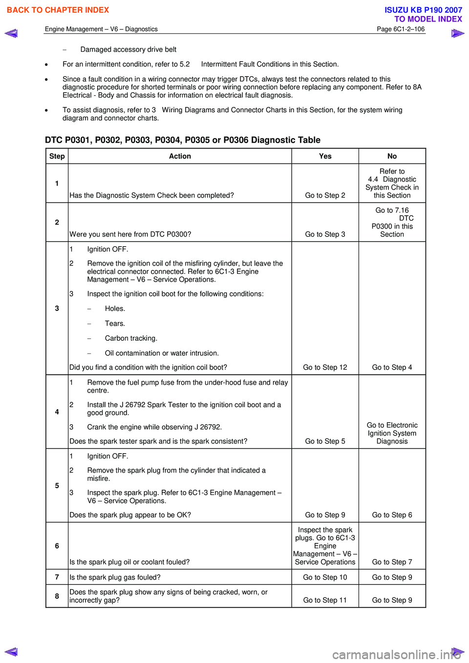
DTC P0301, P0302, P0303, P0304, P0305 or P0306 Diagnostic Table
Step Action Yes No
1
Has the Diagnostic System Check been completed? Go to Step 2 Refer to
4.4 Diagnostic
System Check in this Section
2
W ere you sent here from DTC P0300? Go to Step 3 Go to 7.16
DTC P0300 in this Section
3 1 Ignition OFF.
2 Remove the ignition coil of the misfiring cylinder, but leave the electrical connector connected. Refer to 6C1-3 Engine
Management – V6 – Service Operations.
3 Inspect the ignition coil boot for the following conditions:
− Holes.
− Tears.
− Carbon tracking.
− Oil contamination or water intrusion.
Did you find a condition with the ignition coil boot? Go to Step 12 Go to Step 4
4 1 Remove the fuel pump fuse from the under-hood fuse and relay
centre.
2 Install the J 26792 Spark Tester to the ignition coil boot and a good ground.
3 Crank the engine while observing J 26792.
Does the spark tester spark and is the spark consistent? Go to Step 5 Go to Electronic
Ignition System Diagnosis
5 1 Ignition OFF.
2 Remove the spark plug from the cylinder that indicated a misfire.
3 Inspect the spark plug. Refer to 6C1-3 Engine Management – V6 – Service Operations.
Does the spark plug appear to be OK? Go to Step 9 Go to Step 6
6
Is the spark plug oil or coolant fouled? Inspect the spark
plugs. Go to 6C1-3 Engine
Management – V6 – Service Operations Go to Step 7
7 Is the spark plug gas fouled? Go to Step 10 Go to Step 9
8 Does the spark plug show any signs of being cracked, worn, or
incorrectly gap? Go to Step 11 Go to Step 9
BACK TO CHAPTER INDEX
TO MODEL INDEX
ISUZU KB P190 2007
Page 3385 of 6020
Engine Management – V6 – Diagnostics Page 6C1-2–107
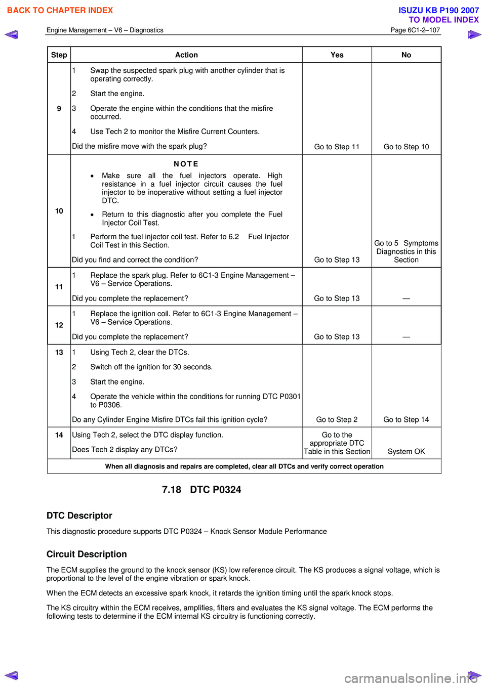
Step Action Yes No
9 1 Swap the suspected spark plug with another cylinder that is
operating correctly.
2 Start the engine.
3 Operate the engine within the conditions that the misfire occurred.
4 Use Tech 2 to monitor the Misfire Current Counters.
Did the misfire move with the spark plug? Go to Step 11 Go to Step 10
10 NOTE
• Make sure all the fuel injectors operate. High
resistance in a fuel injector circuit causes the fuel
injector to be inoperative without setting a fuel injector
DTC.
• Return to this diagnostic after you complete the Fuel
Injector Coil Test.
1 Perform the fuel injector coil test. Refer to 6.2 Fuel Injector Coil Test in this Section.
Did you find and correct the condition? Go to Step 13 Go to 5 Symptoms
Diagnostics in this Section
11 1 Replace the spark plug. Refer to 6C1-3 Engine Management –
V6 – Service Operations.
Did you complete the replacement? Go to Step 13 —
12 1 Replace the ignition coil. Refer to 6C1-3 Engine Management –
V6 – Service Operations.
Did you complete the replacement? Go to Step 13 —
13 1 Using Tech 2, clear the DTCs.
2 Switch off the ignition for 30 seconds.
3 Start the engine.
4 Operate the vehicle within the conditions for running DTC P0301 to P0306.
Do any Cylinder Engine Misfire DTCs fail this ignition cycle? Go to Step 2 Go to Step 14
14 Using Tech 2, select the DTC display function.
Does Tech 2 display any DTCs? Go to the
appropriate DTC
Table in this Section System OK
When all diagnosis and repairs are completed, clear all DTCs and verify correct operation
7.18 DTC P0324
DTC Descriptor
This diagnostic procedure supports DTC P0324 – Knock Sensor Module Performance
Circuit Description
The ECM supplies the ground to the knock sensor (KS) low reference circuit. The KS produces a signal voltage, which is
proportional to the level of the engine vibration or spark knock.
W hen the ECM detects an excessive spark knock, it retards the ignition timing until the spark knock stops.
The KS circuitry within the ECM receives, amplifies, filters and evaluates the KS signal voltage. The ECM performs the
following tests to determine if the ECM internal KS circuitry is functioning correctly.
BACK TO CHAPTER INDEX
TO MODEL INDEX
ISUZU KB P190 2007
Page 3387 of 6020
Engine Management – V6 – Diagnostics Page 6C1-2–109
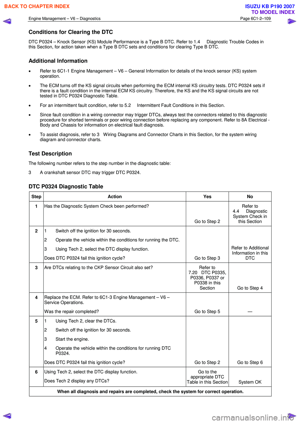
Conditions for Clearing the DTC
DTC P0324 – Knock Sensor (KS) Module Performance is a Type B DTC. Refer to 1.4 Diagnostic Trouble Codes in
this Section, for action taken when a Type B DTC sets and conditions for clearing Type B DTC.
Additional Information
• Refer to 6C1-1 Engine Management – V6 – General Information for details of the knock sensor (KS) system
operation.
• The ECM turns off the KS signal circuits when performing the ECM internal KS circuitry tests. DTC P0324 sets if
there is a fault condition in the internal ECM KS circuitry. Therefore, the KS and the KS signal circuits are not
tested in DTC P0324 Diagnostic Table.
• For an intermittent fault condition, refer to 5.2 Intermittent Fault Conditions in this Section.
• Since fault condition in a wiring connector may trigger DTCs, always test the connectors related to this diagnostic
procedure for shorted terminals or poor wiring connection before replacing any component. Refer to 8A Electrical -
Body and Chassis for information on electrical fault diagnosis.
• To assist diagnosis, refer to 3 W iring Diagrams and Connector Charts in this Section, for the system wiring
diagram and connector charts.
Test Description
The following number refers to the step number in the diagnostic table:
3 A crankshaft sensor DTC may trigger DTC P0324.
DTC P0324 Diagnostic Table
Step Action Yes No
1 Has the Diagnostic System Check been performed?
Go to Step 2 Refer to
4.4 Diagnostic System Check in this Section
2 1 Switch off the ignition for 30 seconds.
2 Operate the vehicle within the conditions for running the DTC.
3 Using Tech 2, select the DTC display function.
Does DTC P0324 fail this ignition cycle? Go to Step 3 Refer to Additional
Information in this DTC
3 Are DTCs relating to the CKP Sensor Circuit also set? Refer to
7.20 DTC P0335, P0336, P0337 or P0338 in this Section Go to Step 4
4 Replace the ECM. Refer to 6C1-3 Engine Management – V6 –
Service Operations.
W as the repair completed? Go to Step 5 —
5 1 Using Tech 2, clear the DTCs.
2 Switch off the ignition for 30 seconds.
3 Start the engine.
4 Operate the vehicle within the conditions for running DTC P0324.
Does DTC P0324 fail this ignition cycle? Go to Step 2 Go to Step 6
6 Using Tech 2, select the DTC display function.
Does Tech 2 display any DTCs? Go to the
appropriate DTC
Table in this Section System OK
When all diagnosis and repairs are completed, check the system for correct operation.
BACK TO CHAPTER INDEX
TO MODEL INDEX
ISUZU KB P190 2007
Page 3389 of 6020
Engine Management – V6 – Diagnostics Page 6C1-2–111
Additional Information
• Refer to 6C1-1 Engine Management – V6 – General Information for details of the knock sensor (KS) system
operation.
• Preconditions for running knock sensor circuit DTCs requires that DTC P0324 has ran and passed. Therefore, the
diagnostic table for the knock sensor circuit DTCs is developed with the assumption the ECM internal KS circuitry
is functioning correctly.
• Excessive engine mechanical noise or engine knocking condition may trigger knock sensor circuit DTCs.
• The knock sensor must be tightened correctly. Refer to 6C1-3 Engine Management – V6 – Service Operations.
• The mounting between the knock sensor and engine must be free of burrs, casting flash and foreign material.
• The knock sensor head must be clear from hoses, brackets and engine wiring.
• If the knock sensor lead is damaged in any way, the sensor must be replaced.
• Since fault condition in a wiring connector may trigger DTCs, always test the connectors related to this diagnostic
procedure for shorted terminals or poor wiring connection before replacing any component. Refer to 8A Electrical -
Body and Chassis for information on electrical fault diagnosis.
• To assist diagnosis, refer to 3 W iring Diagrams and Connector Charts in this Section, for the system wiring
diagram and connector charts.
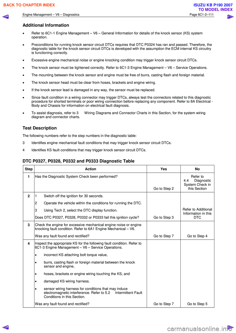
Test Description
The following numbers refer to the step numbers in the diagnostic table:
3 Identifies engine mechanical fault conditions that may trigger knock sensor circuit DTCs.
4 Identifies KS fault conditions that may trigger knock sensor circuit DTCs.
DTC P0327, P0328, P0332 and P0333 Diagnostic Table
Step Action Yes No
1 Has the Diagnostic System Check been performed?
Go to Step 2 Refer to
4.4 Diagnostic System Check in this Section
2 1 Switch off the ignition for 30 seconds.
2 Operate the vehicle within the conditions for running the DTC.
3 Using Tech 2, select the DTC display function.
Does DTC P0327, P0328, P0332 or P0333 fail this ignition cycle? Go to Step 3 Refer to Additional
Information in this DTC
3 Check the engine for excessive mechanical engine noise or engine
knocking fault condition. Refer to 6A1 Engine Mechanical – V6.
W as any fault found and rectified? Go to Step 7 Go to Step 4
4 Inspect the appropriate KS for the following fault condition. Refer to
6C1-3 Engine Management – V6 – Service Operations.
• incorrect KS attaching bolt torque value,
• burrs, casting flash or foreign material between the knock
sensor and engine,
• hoses, brackets or engine wiring touching the KS, and
• damaged KS wiring harness.
• sensor wiring harness for conditions that may induce
electromagnetic interference. Refer to 5.2 Intermittent Fault
Conditions in this Section.
W as any fault found and rectified? Go to Step 7 Go to Step 5
BACK TO CHAPTER INDEX
TO MODEL INDEX
ISUZU KB P190 2007
Page 3390 of 6020
Engine Management – V6 – Diagnostics Page 6C1-2–112
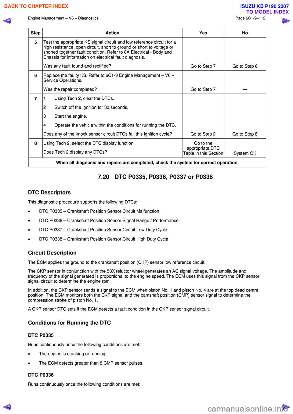
Step Action Yes No
5 Test the appropriate KS signal circuit and low reference circuit for a
high resistance, open circuit, short to ground or short to voltage or
shorted together fault condition. Refer to 8A Electrical - Body and
Chassis for information on electrical fault diagnosis.
W as any fault found and rectified? Go to Step 7 Go to Step 6
6 Replace the faulty KS. Refer to 6C1-3 Engine Management – V6 –
Service Operations.
W as the repair completed? Go to Step 7 —
7 1 Using Tech 2, clear the DTCs.
2 Switch off the ignition for 30 seconds.
3 Start the engine.
4 Operate the vehicle within the conditions for running the DTC.
Does any of the knock sensor circuit DTCs fail this ignition cycle? Go to Step 2 Go to Step 8
8 Using Tech 2, select the DTC display function.
Does Tech 2 display any DTCs? Go to the
appropriate DTC
Table in this Section System OK
When all diagnosis and repairs are completed, check the system for correct operation.
7.20 DTC P0335, P0336, P0337 or P0338
DTC Descriptors
This diagnostic procedure supports the following DTCs:
• DTC P0335 – Crankshaft Position Sensor Circuit Malfunction
• DTC P0336 – Crankshaft Position Sensor Signal Range / Performance
• DTC P0337 – Crankshaft Position Sensor Circuit Low Duty Cycle
• DTC P0338 – Crankshaft Position Sensor Circuit High Duty Cycle
Circuit Description
The ECM applies the ground to the crankshaft position (CKP) sensor low reference circuit.
The CKP sensor in conjunction with the 58X reluctor wheel generates an AC signal voltage. The amplitude and
frequency of the signal generated is proportional to the engine speed. The ECM uses this signal from the CKP sensor
signal circuit to determine the engine rpm
In addition, the CKP sensor sends a signal to the ECM when piston No. 1 and piston No. 4 are at the top dead centre
position. The ECM monitors both the CKP signal and the camshaft position (CMP) sensor signal to determine the
compression stroke of piston No. 1.
A CKP sensor DTC sets if the ECM detects a fault condition in the CKP sensor signal circuit.
Conditions for Running the DTC
DTC P0335
Runs continuously once the following conditions are met:
• The engine is cranking or running.
• The ECM detects greater than 8 CMP sensor pulses.
DTC P0336
Runs continuously once the following conditions are met:
BACK TO CHAPTER INDEX
TO MODEL INDEX
ISUZU KB P190 2007
Page 3392 of 6020
Engine Management – V6 – Diagnostics Page 6C1-2–114
• To assist diagnosis, refer to 3 W iring Diagrams and Connector Charts in this Section, for the system wiring
diagram and connector charts.
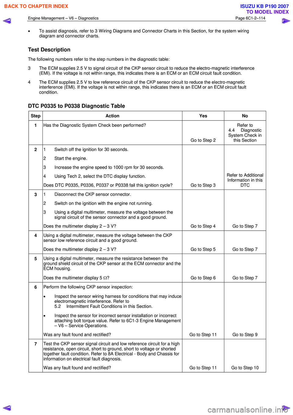
Test Description
The following numbers refer to the step numbers in the diagnostic table:
3 The ECM supplies 2.5 V to signal circuit of the CKP sensor circuit to reduce the electro-magnetic interference (EMI). If the voltage is not within range, this indicates there is an ECM or an ECM circuit fault condition.
4 The ECM supplies 2.5 V to low reference circuit of the CKP sensor circuit to reduce the electro-magnetic interference (EMI). If the voltage is not within range, this indicates there is an ECM or an ECM circuit fault
condition.
DTC P0335 to P0338 Diagnostic Table
Step Action Yes No
1 Has the Diagnostic System Check been performed?
Go to Step 2 Refer to
4.4 Diagnostic
System Check in this Section
2 1 Switch off the ignition for 30 seconds.
2 Start the engine.
3 Increase the engine speed to 1000 rpm for 30 seconds.
4 Using Tech 2, select the DTC display function.
Does DTC P0335, P0336, P0337 or P0338 fail this ignition cycle? Go to Step 3 Refer to Additional
Information in this DTC
3 1 Disconnect the CKP sensor connector.
2 Switch on the ignition with the engine not running.
3 Using a digital multimeter, measure the voltage between the signal circuit of the sensor connector and a good ground.
Does the multimeter display 2 – 3 V? Go to Step 4 Go to Step 7
4 Using a digital multimeter, measure the voltage between the CKP
sensor low reference circuit and a good ground.
Does the multimeter display 2 – 3 V? Go to Step 5 Go to Step 7
5 Using a digital multimeter, measure the resistance between the
ground shield circuit of the CKP sensor at the ECM connector and the
ECM housing.
Does the multimeter display 5 Ω? Go to Step 6 Go to Step 7
6 Perform the following CKP sensor inspection:
• Inspect the sensor wiring harness for conditions that may induce
electromagnetic interference. Refer to
5.2 Intermittent Fault Conditions in this Section.
• Inspect the sensor for incorrect sensor installation or incorrect
attaching bolt torque value. Refer to 6C1-3 Engine Management
– V6 – Service Operations.
W as any fault found and rectified? Go to Step 11 Go to Step 9
7 Test the CKP sensor signal circuit and low reference circuit for a high
resistance, open circuit, short to ground, short to voltage or shorted
together fault condition. Refer to 8A Electrical - Body and Chassis for
information on electrical fault diagnosis.
W as any fault found and rectified? Go to Step 11 Go to Step 10
BACK TO CHAPTER INDEX
TO MODEL INDEX
ISUZU KB P190 2007