2007 ISUZU KB P190 service
[x] Cancel search: servicePage 3444 of 6020
Engine Management – V6 – Diagnostics Page 6C1-2–166
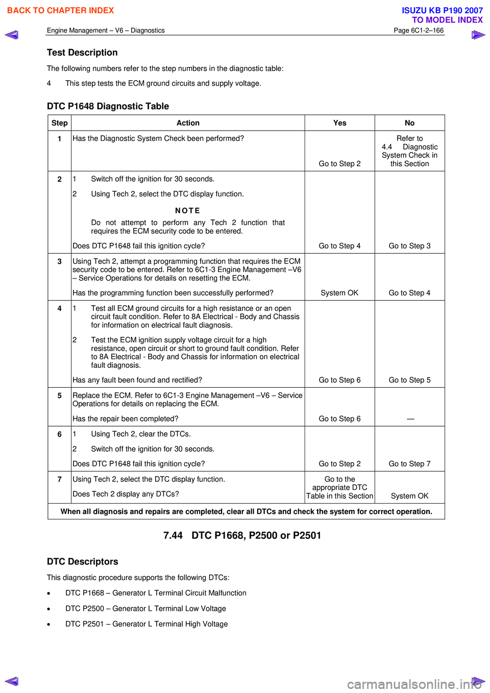
Test Description
The following numbers refer to the step numbers in the diagnostic table:
4 This step tests the ECM ground circuits and supply voltage.
DTC P1648 Diagnostic Table
Step Action Yes No
1 Has the Diagnostic System Check been performed?
Go to Step 2 Refer to
4.4 Diagnostic
System Check in this Section
2 1 Switch off the ignition for 30 seconds.
2 Using Tech 2, select the DTC display function.
NOTE
Do not attempt to perform any Tech 2 function that
requires the ECM security code to be entered.
Does DTC P1648 fail this ignition cycle? Go to Step 4 Go to Step 3
3 Using Tech 2, attempt a programming function that requires the ECM
security code to be entered. Refer to 6C1-3 Engine Management –V6
– Service Operations for details on resetting the ECM.
Has the programming function been successfully performed? System OK Go to Step 4
4 1 Test all ECM ground circuits for a high resistance or an open
circuit fault condition. Refer to 8A Electrical - Body and Chassis
for information on electrical fault diagnosis.
2 Test the ECM ignition supply voltage circuit for a high resistance, open circuit or short to ground fault condition. Refer
to 8A Electrical - Body and Chassis for information on electrical
fault diagnosis.
Has any fault been found and rectified? Go to Step 6 Go to Step 5
5 Replace the ECM. Refer to 6C1-3 Engine Management –V6 – Service
Operations for details on replacing the ECM.
Has the repair been completed? Go to Step 6 —
6 1 Using Tech 2, clear the DTCs.
2 Switch off the ignition for 30 seconds.
Does DTC P1648 fail this ignition cycle? Go to Step 2 Go to Step 7
7 Using Tech 2, select the DTC display function.
Does Tech 2 display any DTCs? Go to the
appropriate DTC
Table in this Section System OK
When all diagnosis and repairs are completed, clear all DTCs and check the system for correct operation.
7.44 DTC P1668, P2500 or P2501
DTC Descriptors
This diagnostic procedure supports the following DTCs:
• DTC P1668 – Generator L Terminal Circuit Malfunction
• DTC P2500 – Generator L Terminal Low Voltage
• DTC P2501 – Generator L Terminal High Voltage
BACK TO CHAPTER INDEX
TO MODEL INDEX
ISUZU KB P190 2007
Page 3446 of 6020
Engine Management – V6 – Diagnostics Page 6C1-2–168
• To assist diagnosis, refer to 3 W iring Diagrams and Connector Charts in this Section, for the system wiring
diagram and connector charts.
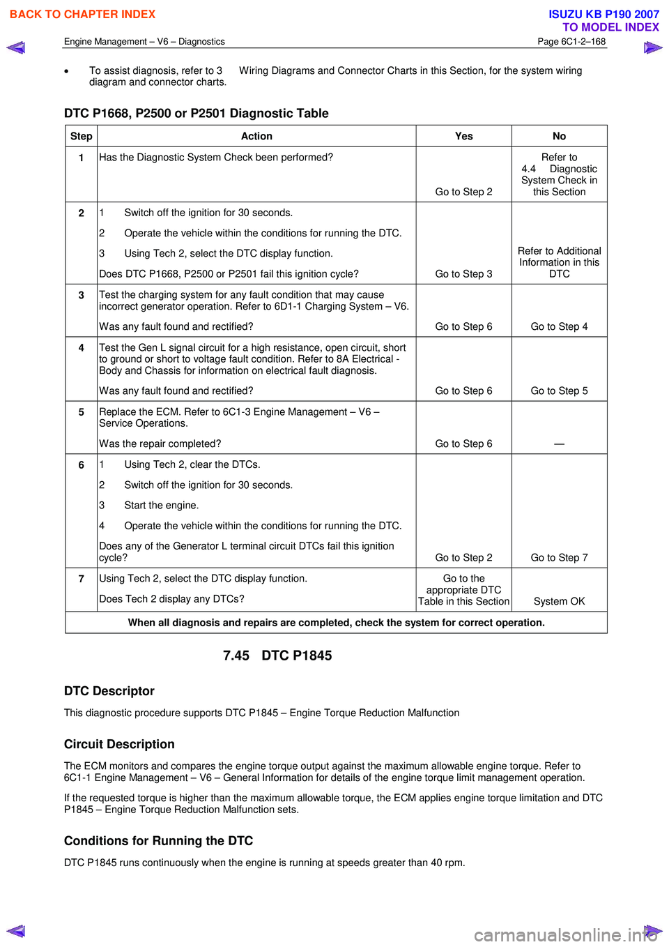
DTC P1668, P2500 or P2501 Diagnostic Table
Step Action Yes No
1 Has the Diagnostic System Check been performed?
Go to Step 2 Refer to
4.4 Diagnostic
System Check in this Section
2 1 Switch off the ignition for 30 seconds.
2 Operate the vehicle within the conditions for running the DTC.
3 Using Tech 2, select the DTC display function.
Does DTC P1668, P2500 or P2501 fail this ignition cycle? Go to Step 3 Refer to Additional
Information in this DTC
3 Test the charging system for any fault condition that may cause
incorrect generator operation. Refer to 6D1-1 Charging System – V6.
W as any fault found and rectified? Go to Step 6 Go to Step 4
4 Test the Gen L signal circuit for a high resistance, open circuit, short
to ground or short to voltage fault condition. Refer to 8A Electrical -
Body and Chassis for information on electrical fault diagnosis.
W as any fault found and rectified? Go to Step 6 Go to Step 5
5 Replace the ECM. Refer to 6C1-3 Engine Management – V6 –
Service Operations.
W as the repair completed? Go to Step 6 —
6 1 Using Tech 2, clear the DTCs.
2 Switch off the ignition for 30 seconds.
3 Start the engine.
4 Operate the vehicle within the conditions for running the DTC.
Does any of the Generator L terminal circuit DTCs fail this ignition
cycle? Go to Step 2 Go to Step 7
7 Using Tech 2, select the DTC display function.
Does Tech 2 display any DTCs? Go to the
appropriate DTC
Table in this Section System OK
When all diagnosis and repairs are completed, check the system for correct operation.
7.45 DTC P1845
DTC Descriptor
This diagnostic procedure supports DTC P1845 – Engine Torque Reduction Malfunction
Circuit Description
The ECM monitors and compares the engine torque output against the maximum allowable engine torque. Refer to
6C1-1 Engine Management – V6 – General Information for details of the engine torque limit management operation.
If the requested torque is higher than the maximum allowable torque, the ECM applies engine torque limitation and DTC
P1845 – Engine Torque Reduction Malfunction sets.
Conditions for Running the DTC
DTC P1845 runs continuously when the engine is running at speeds greater than 40 rpm.
BACK TO CHAPTER INDEX
TO MODEL INDEX
ISUZU KB P190 2007
Page 3447 of 6020
Engine Management – V6 – Diagnostics Page 6C1-2–169
Conditions for Setting the DTC
The engine torque output exceeds the maximum allowable torque output for 10 minutes.
Conditions for Clearing the DTC
DTC P1845 – Engine Torque Reduction Malfunction is a Type ‘C’ DTC. Refer to 1.4 Diagnostic Trouble Codes in this
Section, for action taken when a Type ‘C’ DTC sets and conditions for clearing Type ‘C’ DTC.
Additional Information
• Refer to 6C1-1 Engine Management – V6 – General Information for details of the Engine Torque Limit
Management operation.
• For an intermittent fault condition, refer to 5.2 Intermittent Fault Conditions in this Section.
• Since fault condition in a wiring connector may trigger DTCs, always test the connectors related to this diagnostic
procedure for shorted terminals or poor wiring connection before replacing any component. Refer to 8A Electrical -
Body and Chassis for information on electrical fault diagnosis.
• To assist diagnosis, refer to 3 W iring Diagrams and Connector Charts in this Section, for the system wiring
diagram and connector charts.
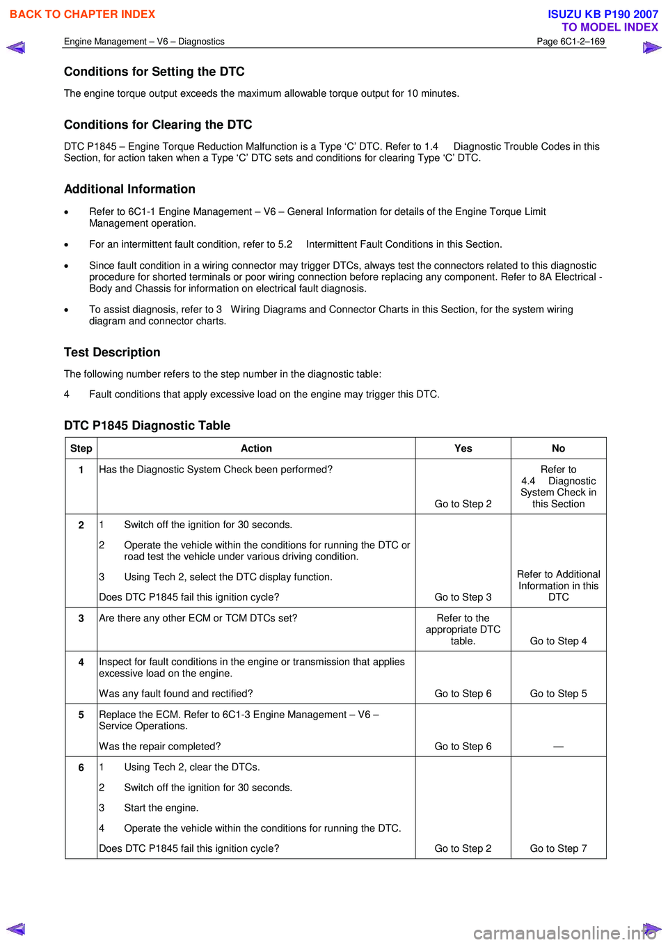
Test Description
The following number refers to the step number in the diagnostic table:
4 Fault conditions that apply excessive load on the engine may trigger this DTC.
DTC P1845 Diagnostic Table
Step Action Yes No
1 Has the Diagnostic System Check been performed?
Go to Step 2 Refer to
4.4 Diagnostic
System Check in this Section
2 1 Switch off the ignition for 30 seconds.
2 Operate the vehicle within the conditions for running the DTC or road test the vehicle under various driving condition.
3 Using Tech 2, select the DTC display function.
Does DTC P1845 fail this ignition cycle? Go to Step 3 Refer to Additional
Information in this DTC
3 Are there any other ECM or TCM DTCs set? Refer to the
appropriate DTC table. Go to Step 4
4 Inspect for fault conditions in the engine or transmission that applies
excessive load on the engine.
W as any fault found and rectified? Go to Step 6 Go to Step 5
5 Replace the ECM. Refer to 6C1-3 Engine Management – V6 –
Service Operations.
W as the repair completed? Go to Step 6 —
6 1 Using Tech 2, clear the DTCs.
2 Switch off the ignition for 30 seconds.
3 Start the engine.
4 Operate the vehicle within the conditions for running the DTC.
Does DTC P1845 fail this ignition cycle? Go to Step 2 Go to Step 7
BACK TO CHAPTER INDEX
TO MODEL INDEX
ISUZU KB P190 2007
Page 3451 of 6020
Engine Management – V6 – Diagnostics Page 6C1-2–173
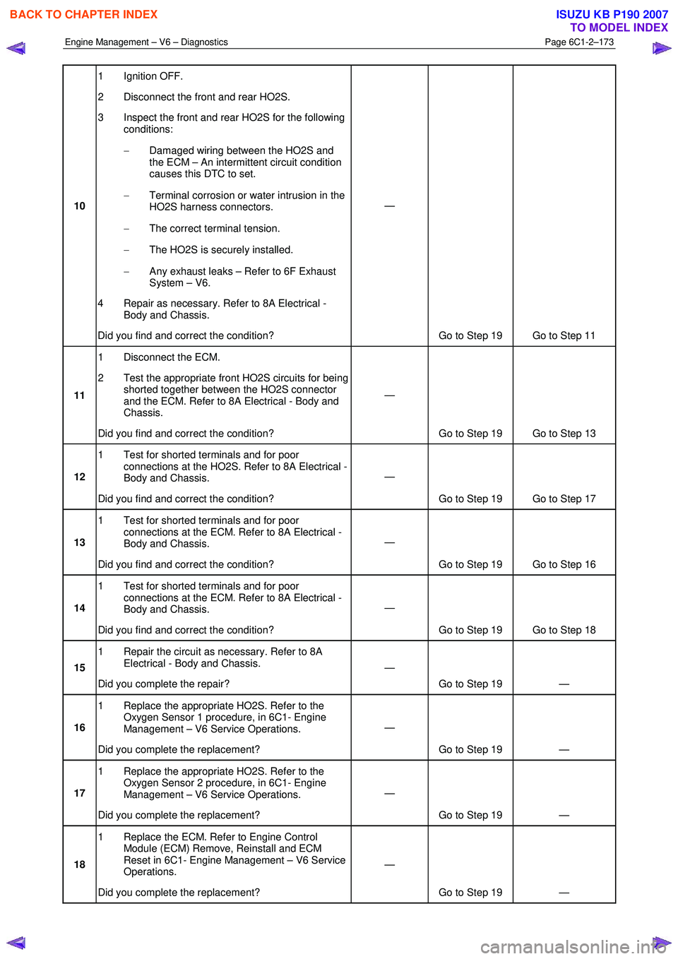
10 1 Ignition OFF.
2 Disconnect the front and rear HO2S.
3 Inspect the front and rear HO2S for the following conditions:
− Damaged wiring between the HO2S and
the ECM – An intermittent circuit condition
causes this DTC to set.
− Terminal corrosion or water intrusion in the
HO2S harness connectors.
− The correct terminal tension.
− The HO2S is securely installed.
− Any exhaust leaks – Refer to 6F Exhaust
System – V6.
4 Repair as necessary. Refer to 8A Electrical - Body and Chassis.
Did you find and correct the condition? —
Go to Step 19 Go to Step 11
11 1 Disconnect the ECM.
2 Test the appropriate front HO2S circuits for being shorted together between the HO2S connector
and the ECM. Refer to 8A Electrical - Body and
Chassis.
Did you find and correct the condition? —
Go to Step 19 Go to Step 13
12 1 Test for shorted terminals and for poor
connections at the HO2S. Refer to 8A Electrical -
Body and Chassis.
Did you find and correct the condition? —
Go to Step 19 Go to Step 17
13 1 Test for shorted terminals and for poor
connections at the ECM. Refer to 8A Electrical -
Body and Chassis.
Did you find and correct the condition? —
Go to Step 19 Go to Step 16
14 1 Test for shorted terminals and for poor
connections at the ECM. Refer to 8A Electrical -
Body and Chassis.
Did you find and correct the condition? —
Go to Step 19 Go to Step 18
15 1 Repair the circuit as necessary. Refer to 8A
Electrical - Body and Chassis.
Did you complete the repair? —
Go to Step 19 —
16 1 Replace the appropriate HO2S. Refer to the
Oxygen Sensor 1 procedure, in 6C1- Engine
Management – V6 Service Operations.
Did you complete the replacement? —
Go to Step 19 —
17 1 Replace the appropriate HO2S. Refer to the
Oxygen Sensor 2 procedure, in 6C1- Engine
Management – V6 Service Operations.
Did you complete the replacement? —
Go to Step 19 —
18 1 Replace the ECM. Refer to Engine Control
Module (ECM) Remove, Reinstall and ECM
Reset in 6C1- Engine Management – V6 Service
Operations.
Did you complete the replacement? —
Go to Step 19 —
BACK TO CHAPTER INDEX
TO MODEL INDEX
ISUZU KB P190 2007
Page 3455 of 6020
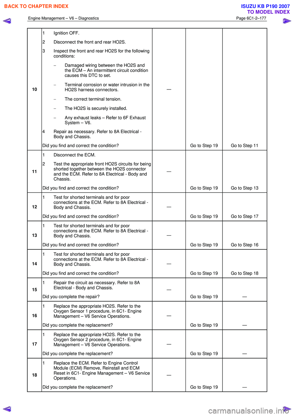
Engine Management – V6 – Diagnostics Page 6C1-2–177
10 1 Ignition OFF.
2 Disconnect the front and rear HO2S.
3 Inspect the front and rear HO2S for the following conditions:
− Damaged wiring between the HO2S and
the ECM – An intermittent circuit condition
causes this DTC to set.
− Terminal corrosion or water intrusion in the
HO2S harness connectors.
− The correct terminal tension.
− The HO2S is securely installed.
− Any exhaust leaks – Refer to 6F Exhaust
System – V6.
4 Repair as necessary. Refer to 8A Electrical - Body and Chassis.
Did you find and correct the condition? —
Go to Step 19 Go to Step 11
11 1 Disconnect the ECM.
2 Test the appropriate front HO2S circuits for being shorted together between the HO2S connector
and the ECM. Refer to 8A Electrical - Body and
Chassis.
Did you find and correct the condition? —
Go to Step 19 Go to Step 13
12 1 Test for shorted terminals and for poor
connections at the ECM. Refer to 8A Electrical -
Body and Chassis.
Did you find and correct the condition? —
Go to Step 19 Go to Step 17
13 1 Test for shorted terminals and for poor
connections at the ECM. Refer to 8A Electrical -
Body and Chassis.
Did you find and correct the condition? —
Go to Step 19 Go to Step 16
14 1 Test for shorted terminals and for poor
connections at the ECM. Refer to 8A Electrical -
Body and Chassis.
Did you find and correct the condition? —
Go to Step 19 Go to Step 18
15 1 Repair the circuit as necessary. Refer to 8A
Electrical - Body and Chassis.
Did you complete the repair? —
Go to Step 19 —
16 1 Replace the appropriate HO2S. Refer to the
Oxygen Sensor 1 procedure, in 6C1- Engine
Management – V6 Service Operations.
Did you complete the replacement? —
Go to Step 19 —
17 1 Replace the appropriate HO2S. Refer to the
Oxygen Sensor 2 procedure, in 6C1- Engine
Management – V6 Service Operations.
Did you complete the replacement? —
Go to Step 19 —
18 1 Replace the ECM. Refer to Engine Control
Module (ECM) Remove, Reinstall and ECM
Reset in 6C1- Engine Management – V6 Service
Operations.
Did you complete the replacement? —
Go to Step 19 —
BACK TO CHAPTER INDEX
TO MODEL INDEX
ISUZU KB P190 2007
Page 3457 of 6020
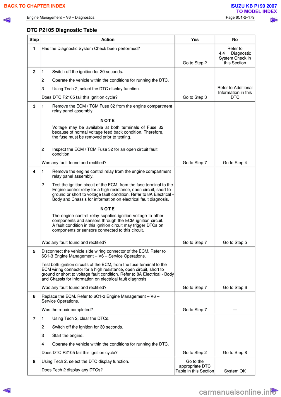
Engine Management – V6 – Diagnostics Page 6C1-2–179
DTC P2105 Diagnostic Table
Step Action Yes No
1 Has the Diagnostic System Check been performed?
Go to Step 2 Refer to
4.4 Diagnostic
System Check in this Section
2 1 Switch off the ignition for 30 seconds.
2 Operate the vehicle within the conditions for running the DTC.
3 Using Tech 2, select the DTC display function.
Does DTC P2105 fail this ignition cycle? Go to Step 3 Refer to Additional
Information in this DTC
3 1 Remove the ECM / TCM Fuse 32 from the engine compartment
relay panel assembly.
NOTE
Voltage may be available at both terminals of Fuse 32
because of normal voltage feed back condition. Therefore,
the fuse must be removed prior to testing.
2 Inspect the ECM / TCM Fuse 32 for an open circuit fault condition.
W as any fault found and rectified? Go to Step 7 Go to Step 4
4 1 Remove the engine control relay from the engine compartment
relay panel assembly.
2 Test the ignition circuit of the ECM, from the fuse terminal to the Engine control relay for a high resistance, open circuit, short to
ground or short to voltage fault condition. Refer to 8A Electrical -
Body and Chassis for information on electrical fault diagnosis.
NOTE
The engine control relay supplies ignition voltage to other
components and sensors through the ECM ignition circuit.
A fault condition in this ignition circuit may trigger DTCs on
components or sensors connected to this circuit.
W as any fault found and rectified? Go to Step 7 Go to Step 5
5 Disconnect the vehicle side wiring connector of the ECM. Refer to
6C1-3 Engine Management – V6 – Service Operations.
Test both ignition circuits of the ECM, from the fuse terminal to the
ECM wiring connector for a high resistance, open circuit, short to
ground or short to voltage fault condition. Refer to 8A Electrical - Body
and Chassis for information on electrical fault diagnosis.
W as any fault found and rectified? Go to Step 7 Go to Step 6
6 Replace the ECM. Refer to 6C1-3 Engine Management – V6 –
Service Operations.
W as the repair completed? Go to Step 7 —
7 1 Using Tech 2, clear the DTCs.
2 Switch off the ignition for 30 seconds.
3 Start the engine.
4 Operate the vehicle within the conditions for running the DTC.
Does DTC P2105 fail this ignition cycle? Go to Step 2 Go to Step 8
8 Using Tech 2, select the DTC display function.
Does Tech 2 display any DTCs? Go to the
appropriate DTC
Table in this Section System OK
BACK TO CHAPTER INDEX
TO MODEL INDEX
ISUZU KB P190 2007
Page 3459 of 6020
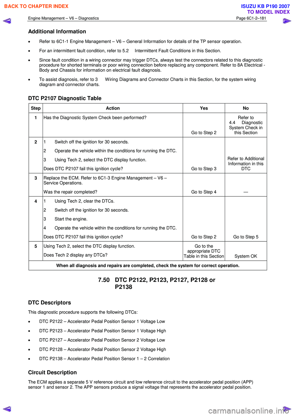
Engine Management – V6 – Diagnostics Page 6C1-2–181
Additional Information
• Refer to 6C1-1 Engine Management – V6 – General Information for details of the TP sensor operation.
• For an intermittent fault condition, refer to 5.2 Intermittent Fault Conditions in this Section.
• Since fault condition in a wiring connector may trigger DTCs, always test the connectors related to this diagnostic
procedure for shorted terminals or poor wiring connection before replacing any component. Refer to 8A Electrical -
Body and Chassis for information on electrical fault diagnosis.
• To assist diagnosis, refer to 3 W iring Diagrams and Connector Charts in this Section, for the system wiring
diagram and connector charts.
DTC P2107 Diagnostic Table
Step Action Yes No
1 Has the Diagnostic System Check been performed?
Go to Step 2 Refer to
4.4 Diagnostic
System Check in this Section
2 1 Switch off the ignition for 30 seconds.
2 Operate the vehicle within the conditions for running the DTC.
3 Using Tech 2, select the DTC display function.
Does DTC P2107 fail this ignition cycle? Go to Step 3 Refer to Additional
Information in this DTC
3 Replace the ECM. Refer to 6C1-3 Engine Management – V6 –
Service Operations.
W as the repair completed? Go to Step 4 —
4 1 Using Tech 2, clear the DTCs.
2 Switch off the ignition for 30 seconds.
3 Start the engine.
4 Operate the vehicle within the conditions for running the DTC.
Does DTC P2107 fail this ignition cycle? Go to Step 2 Go to Step 5
5 Using Tech 2, select the DTC display function.
Does Tech 2 display any DTCs? Go to the
appropriate DTC
Table in this Section System OK
When all diagnosis and repairs are completed, check the system for correct operation.
7.50 DTC P2122, P2123, P2127, P2128 or
P2138
DTC Descriptors
This diagnostic procedure supports the following DTCs:
• DTC P2122 – Accelerator Pedal Position Sensor 1 Voltage Low
• DTC P2123 – Accelerator Pedal Position Sensor 1 Voltage High
• DTC P2127 – Accelerator Pedal Position Sensor 2 Voltage Low
• DTC P2128 – Accelerator Pedal Position Sensor 2 Voltage High
• DTC P2138 – Accelerator Pedal Position Sensor 1 – 2 Correlation
Circuit Description
The ECM applies a separate 5 V reference circuit and low reference circuit to the accelerator pedal position (APP)
sensor 1 and sensor 2. The APP sensors produce a signal voltage that represents the accelerator pedal position.
BACK TO CHAPTER INDEX
TO MODEL INDEX
ISUZU KB P190 2007
Page 3462 of 6020
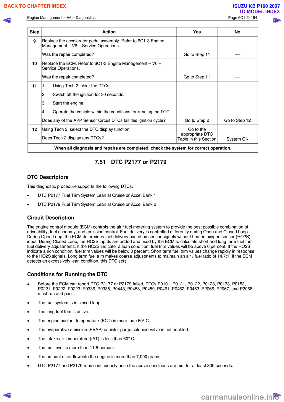
Engine Management – V6 – Diagnostics Page 6C1-2–184
Step Action Yes No
9 Replace the accelerator pedal assembly. Refer to 6C1-3 Engine
Management – V6 – Service Operations.
W as the repair completed? Go to Step 11 —
10 Replace the ECM. Refer to 6C1-3 Engine Management – V6 –
Service Operations.
W as the repair completed? Go to Step 11 —
11 1 Using Tech 2, clear the DTCs.
2 Switch off the ignition for 30 seconds.
3 Start the engine.
4 Operate the vehicle within the conditions for running the DTC.
Does any of the APP Sensor Circuit DTCs fail this ignition cycle? Go to Step 2 Go to Step 12
12 Using Tech 2, select the DTC display function.
Does Tech 2 display any DTCs? Go to the
appropriate DTC
Table in this Section System OK
When all diagnosis and repairs are completed, check the system for correct operation.
7.51 DTC P2177 or P2179
DTC Descriptors
This diagnostic procedure supports the following DTCs:
• DTC P2177 Fuel Trim System Lean at Cruise or Accel Bank 1
• DTC P2179 Fuel Trim System Lean at Cruise or Accel Bank 2
Circuit Description
The engine control module (ECM) controls the air / fuel metering system to provide the best possible combination of
driveability, fuel economy, and emission control. Fuel delivery is controlled differently during Open and Closed Loop.
During Open Loop, the ECM determines fuel delivery based on sensor signals without heated oxygen sensor (HO2S)
input. During Closed Loop, the HO2S inputs are added and used by the ECM to calculate short and long term fuel trim
fuel delivery adjustments. If the HO2S indicate a lean condition, fuel trim values will be above 0 percent. If the HO2S
indicate a rich condition, fuel trim values will be below 0 percent. Short term fuel trim values change rapidly in response
to the HO2S signals. Long term fuel trim makes coarse adjustments to maintain an air / fuel ratio of 14.7:1. If the ECM
detects an excessively lean condition, this DTC sets.
Conditions for Running the DTC
• Before the ECM can report DTC P2177 or P2179 failed, DTCs P0101, P0121, P0122, P0123, P0133, P0153,
P0221, P0222, P0223, P0336, P0338, P0443, P0458, P0459, P0461, P0462, P0463, P2066, P2067, and P2068
must run and pass.
• The fuel system is in closed loop.
• The long fuel trim is active.
• The engine coolant temperature (ECT) is more than 60° C.
• The evaporative emission (EVAP) canister purge solenoid valve is not enabled.
• The intake air temperature (IAT) is less than 60° C.
• The fuel level is more than 11.6 percent.
• The amount of air flow into the engine is more than 7,000 grams.
• DTC P2177 and P2179 runs continuously once the above conditions are met for at least 300 seconds.
BACK TO CHAPTER INDEX
TO MODEL INDEX
ISUZU KB P190 2007