2007 ISUZU KB P190 CIRCUIT DIAGRAM
[x] Cancel search: CIRCUIT DIAGRAMPage 5597 of 6020
Cruise Control – HFV6 Page 8C–19
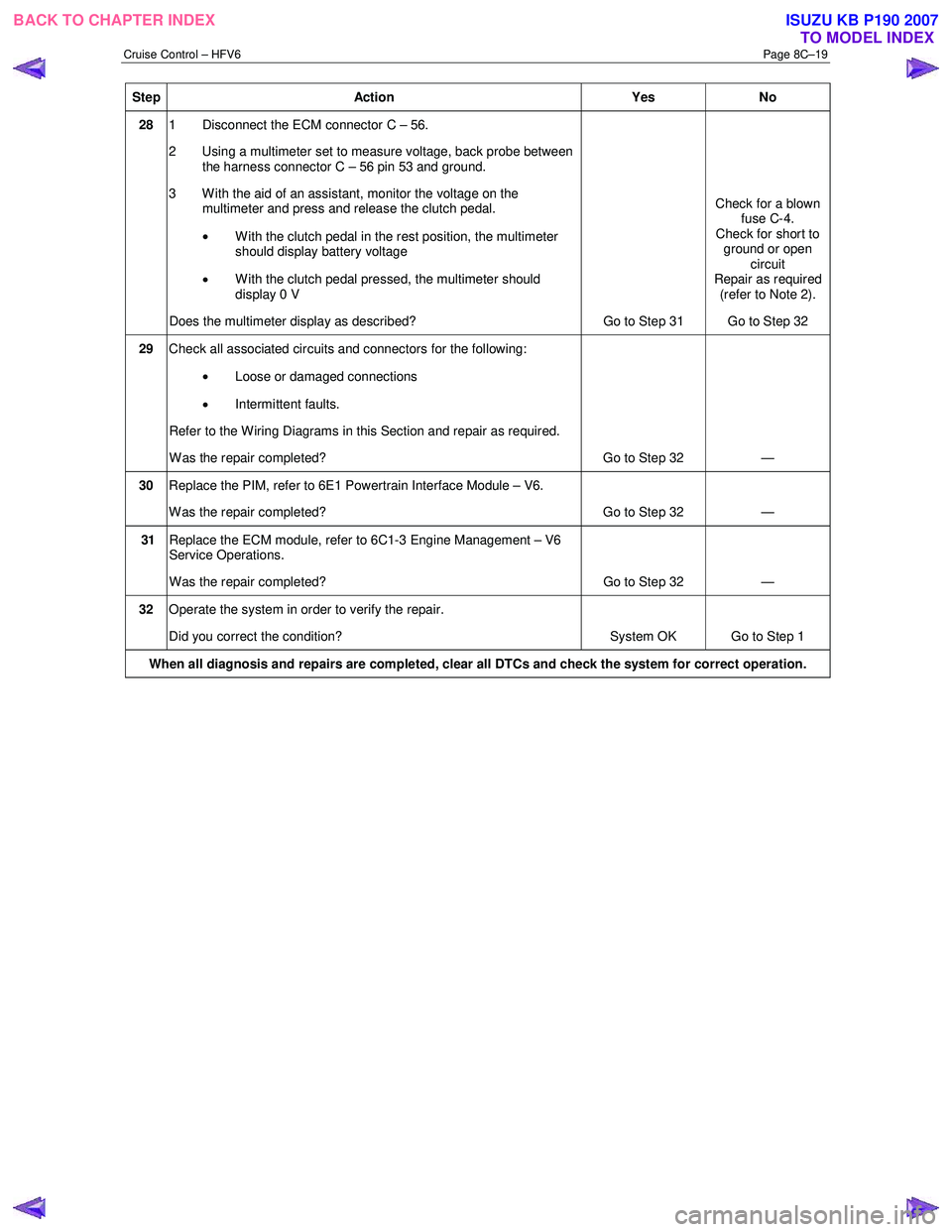
Step Action Yes No
28 1 Disconnect the ECM connector C – 56.
2 Using a multimeter set to measure voltage, back probe between the harness connector C – 56 pin 53 and ground.
3 W ith the aid of an assistant, monitor the voltage on the multimeter and press and release the clutch pedal.
• With the clutch pedal in the rest position, the multimeter
should display battery voltage
• W ith the clutch pedal pressed, the multimeter should
display 0 V
Does the multimeter display as described? Go to Step 31 Check for a blown
fuse C-4.
Check for short to ground or open circuit
Repair as required (refer to Note 2).
Go to Step 32
29 Check all associated circuits and connectors for the following:
• Loose or damaged connections
• Intermittent faults.
Refer to the Wiring Diagrams in this Section and repair as required.
W as the repair completed? Go to Step 32 —
30 Replace the PIM, refer to 6E1 Powertrain Interface Module – V6.
W as the repair completed? Go to Step 32 —
31 Replace the ECM module, refer to 6C1-3 Engine Management – V6
Service Operations.
W as the repair completed? Go to Step 32 —
32 Operate the system in order to verify the repair.
Did you correct the condition? System OK Go to Step 1
When all diagnosis and repairs are completed, clear all DTCs and check the system for correct operation.
BACK TO CHAPTER INDEX
TO MODEL INDEXISUZU KB P190 2007
Page 5606 of 6020
ACCESSORIES 9-1
SECTION 9
ACCESSORIES
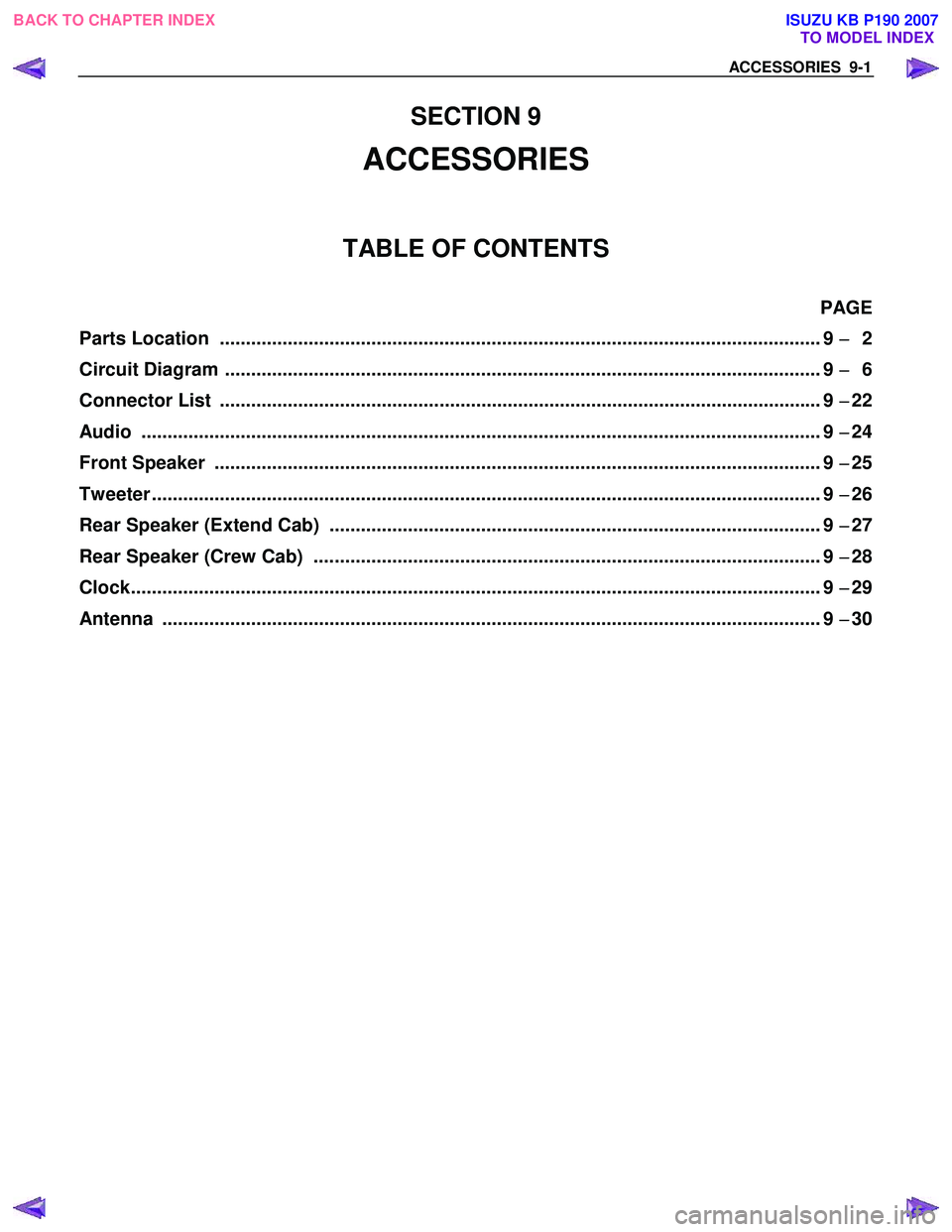
TABLE OF CONTENTS
PAGE
Parts Location ................................................................................................................ ... 9 −
−−
−
2
Circuit Diagram ............................................................................................................... ... 9 −
−−
−
6
Connector List ................................................................................................................ ... 9 −
−−
−
22
Audio ......................................................................................................................... ......... 9 −
−−
−
24
Front Speaker ................................................................................................................. ... 9 −
−−
−
25
Tweeter ........................................................................................................................ ........ 9 −
−−
−
26
Rear Speaker (Extend Cab) .............................................................................................. 9 −
−−
−
27
Rear Speaker (Crew Cab) ................................................................................................. 9 −
−−
−
28
Clock.......................................................................................................................... .......... 9 −
−−
−
29
Antenna ....................................................................................................................... ....... 9 −
−−
−
30
BACK TO CHAPTER INDEX
TO MODEL INDEXISUZU KB P190 2007
Page 5611 of 6020
9-6 ACCESSORIES
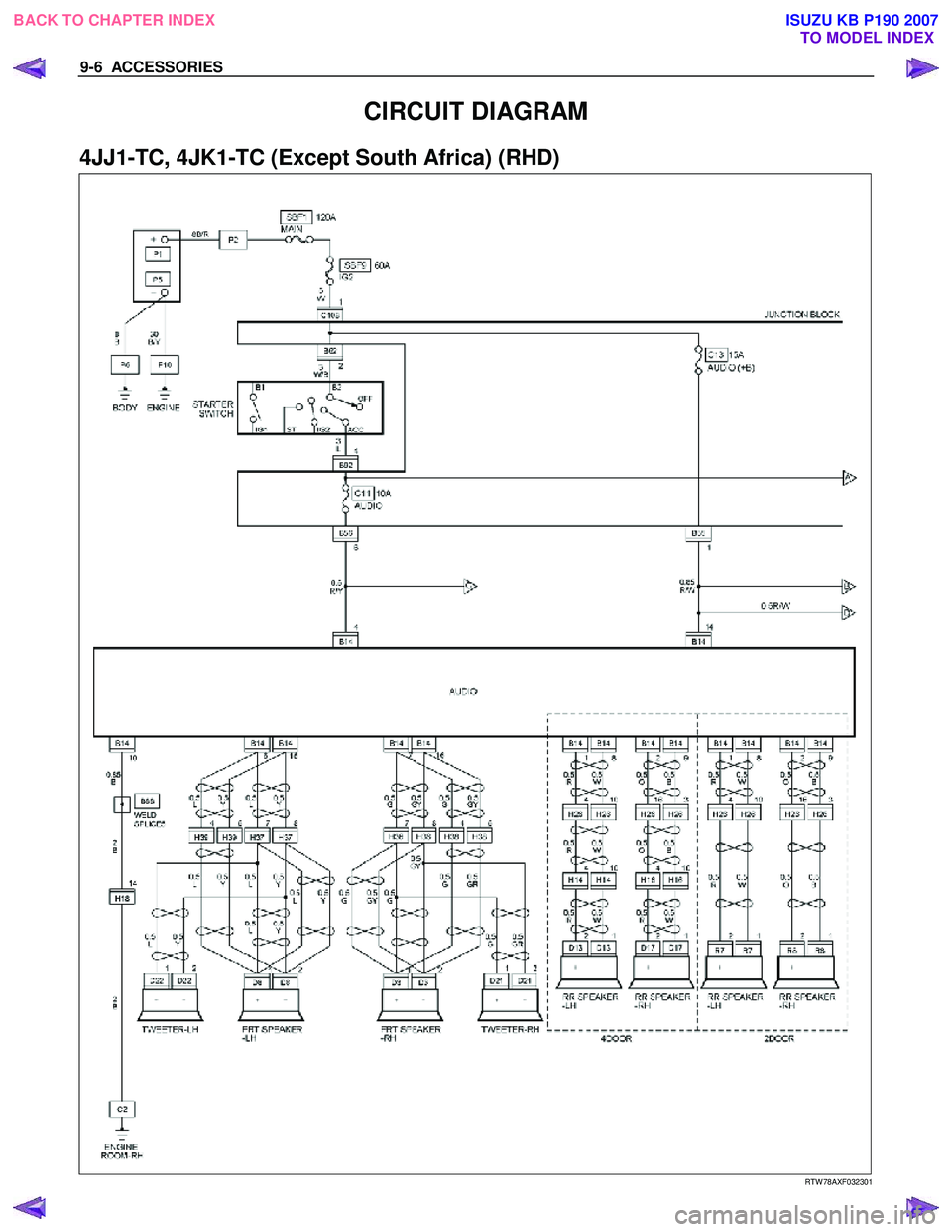
CIRCUIT DIAGRAM
4JJ1-TC, 4JK1-TC (Except South Africa) (RHD)
RTW 78AXF032301
BACK TO CHAPTER INDEX
TO MODEL INDEXISUZU KB P190 2007
Page 5636 of 6020
SUPPLEMENTAL RESTRAINT SYSTEM 9A-1
SECTION 9A
SUPPLEMENTAL RESTRAINT SYSTEM (SRS)
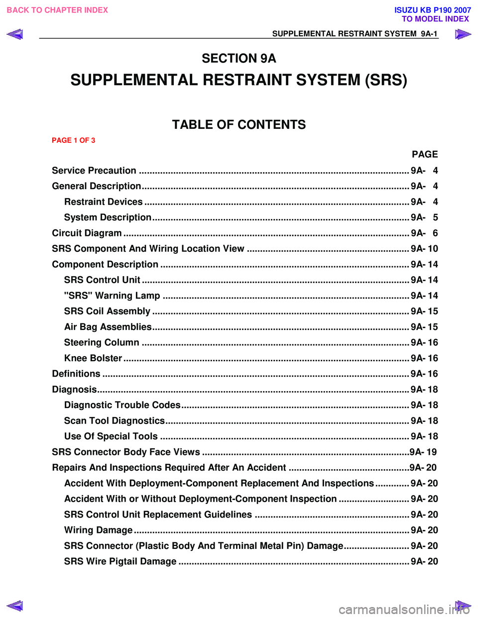
TABLE OF CONTENTS
PAGE
Service Precaution ....................................................................................................... 9A- 4
General Description...................................................................................................... 9A- 4 Restraint Devices ..................................................................................................... 9A- 4
System Description .................................................................................................. 9A- 5
Circuit Diagram ............................................................................................................. 9A- 6
SRS Component And Wiring Location View .............................................................. 9A- 10
Component Description ............................................................................................... 9A- 14 SRS Control Unit ...................................................................................................... 9A- 14
"SRS" Warning Lamp .............................................................................................. 9A- 14
SRS Coil Assembly .................................................................................................. 9A- 15
Air Bag Assemblies.................................................................................................. 9A- 15
Steering Column ...................................................................................................... 9A- 16
Knee Bolster ............................................................................................................. 9A- 16
Definitions .................................................................................................................... . 9A- 16
Diagnosis...................................................................................................................... . 9A- 18
Diagnostic Trouble Codes ....................................................................................... 9A- 18
Scan Tool Diagnostics............................................................................................. 9A- 18
Use Of Special Tools ............................................................................................... 9A- 18
SRS Connec tor Body Face Vie ws ............................................................................. ..9 A- 19
Repairs And Inspec tions Required After A n A ccident ............................................ ..9 A- 20
Accident With Deployment-Component Replacement And Inspections ............. 9A- 20
Accident With or Without Deployment-Component Inspection ........................... 9A- 20
SRS Control Unit Replacement Guidelines ........................................................... 9A- 20
Wiring Damage ......................................................................................................... 9A- 20
SRS Connector (Plastic Body And Terminal Metal Pin) Damage ......................... 9A- 20
SRS Wire Pigtail Damage ........................................................................................ 9A- 20
PAGE 1 OF 3
BACK TO CHAPTER INDEX TO MODEL INDEXISUZU KB P190 2007
Page 5641 of 6020
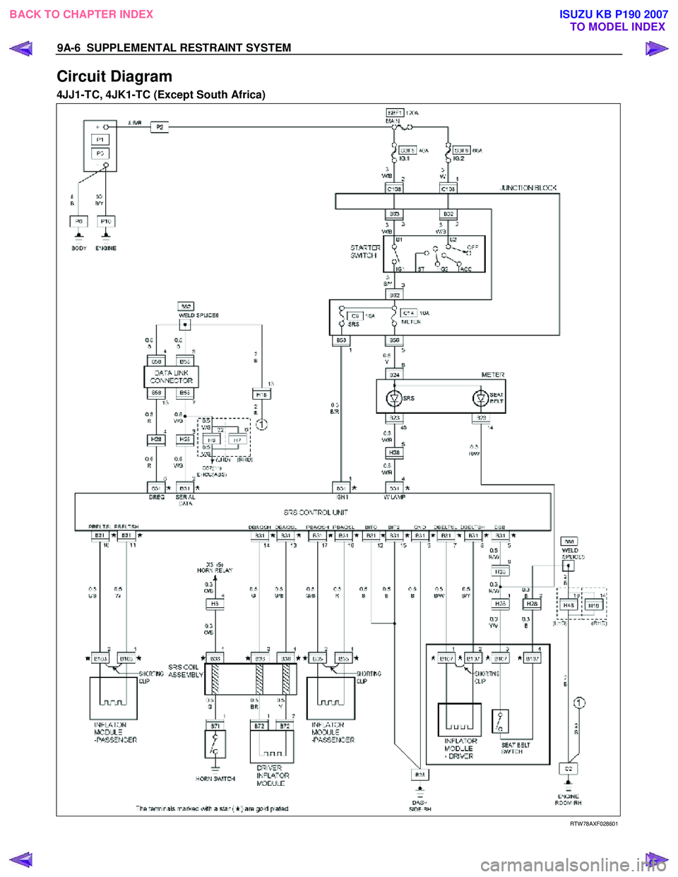
9A-6 SUPPLEMENTAL RESTRAINT SYSTEM
Circuit Diagram
4JJ1-TC, 4JK1-TC (Except South Africa)
RTW 78AXF028601
BACK TO CHAPTER INDEX
TO MODEL INDEXISUZU KB P190 2007
Page 5686 of 6020
9A1-4 RESTRAINT CONTROL SYSTEM
Basic Knowledge Required
Before using this section of the Service Manual, some
basic knowledge is required. W ithout this knowledge,
you will have trouble using the diagnostic procedures in
this section. Use care to prevent any harm or unwanted
deployment. Read all cautions in the service manual
and on warning labels attached to SRS components.
Basic Electrical Circuits
You should understand the basic theory of electricity
including series and parallel circuits, and understand
the voltage drops across series resistors. You should
know the meaning of voltage (volts), current (amps),
and resistance (ohms). You should understand what
happens in a circuit with an open or a shorted wire. You
should be able to read and understand a wiring
diagram.
“Flash Code” Diagnostics
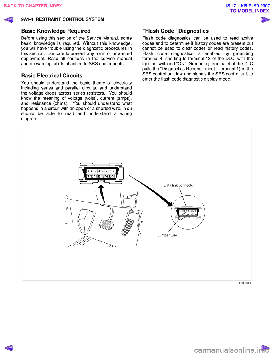
Flash code diagnostics can be used to read active
codes and to determine if history codes are present but
cannot be used to clear codes or read history codes.
Flash code diagnostics is enabled by grounding
terminal 4, shorting to terminal 13 of the DLC, with the
ignition switched “ON”. Grounding terminal 4 of the DLC
pulls the “Diagnostics Request” input (Terminal 1) of the
SRS control unit low and signals the SRS control unit to
enter the flash code diagnostic display mode.
060R300052
BACK TO CHAPTER INDEX TO MODEL INDEX
ISUZU KB P190 2007
Page 5899 of 6020
IMMOBILIZER SYSTEM (C24SE, 4JA1-T) 11A-1
IMMOBILIZER SYSTEM
(C24SE, 4JA1-T)
CONTENTS
Service Precaution .................................................. 11A-2
General Description ................................................ 11A-3
W hat happens without proper transponder
operation? ........................................................... 11A-5
No proper transponder is available, what
should be done for the system? ...................... 11A-5
Caution to the operation ..................................... 11A-5
Summary of operation ......................................... 11A-5
W hat your organization should provide for
your customer .................................................... 11A-5
Car Pass .............................................................. 11A-5
Security code management .............................. 11A-5
Essential tool (Scan tool : Tech-2) .................. 11A-5
Circuit Diagram .................................................. 11A-6
Parts Location .......................................................... 11A-8
Immobilizer control unit (ICU); For Electronic
Control Engine (C24SE) .................................... 11A-9
Pin-outs; For Electronic Control Engine
(C24SE) ............................................................... 11A-10
Immobilizer control unit (ICU); Mechanical
Control Engine (4JA1-T) ...................................11A-11
Immobilizer coil (Antenna) ....................................11A-13
Transponder (Key) ............................................11A-13
Check engine lamp ...........................................11A-13
Engine control module (ECM) ...........................11A-13
Car Pass Card ...................................................11A-14 Loss of car pass card .......................................... 11A-14
Instructions on Filling Out the form "Data
request, car pass" ............................................. 11A-14
Important Instructions ........................................ 11A-15
lmportant information on Programming ..............11A-17
Security code ....................................................... 11A-17
Entering a code ................................................... 11A-17
Transponder (Key) ............................................. 11A-17
Tech-2 Scan Tool .................................................. 11A-18
Operating Procedure .......................................... 11A-18
Menu .................................................................... 11A-19
DTC ...................................................................... 11A-19
Clear DTC Information ......................................11A-19
Tech-2 Data Display .......................................... 11A-19
Check Vehicle Identification Number (VIN) ....11A-19
Reset Immobilizer (Reset Immobilizer
Control Unit) ....................................................... 11A-19
Reset Engine Control Module (Reset ECM) ..11A-20
Erase transponder key ......................................11A-20
Programming Immobilizer Function ................11A-21
Programming ICU .............................................. 11A-22
Programming ECM ............................................ 11A-23
Programming ICU and ECM .............................11A-24
Transponder program ........................................ 11A-24
Data List .............................................................. 11A-26
Diagnostic procedure ............................................ 11A-27
Clearing Diagnostic Trouble Codes ....................11A-27
Verifying Vehicle Repair .......................................11A-27
Diagnostic Aids ...................................................... 11A-27
Check the condition for system parts ..............11A-27
Check the Electro-Magnetic Interference
(EMI) ................................................................... 11A-27
Check the other items .......................................11A-27
Check the operation ........................................... 11A-27
Diagnostic Trouble Code (DTC) list ....................11A-28
IMMOBILIZER SYSTEM CHECK .......................11A-30
NO IMMOBILIZER W ARNING LAMP ................11A-32
CHECK IMMOBILIZER W ARNING LAMP O
STEADY ................................................................ 11A-33
B0001 REPLACE ELECTRONIC CONTROL
UNIT (ECU) (IMMOBILIZER FAULT) ................11A-34
B0002 IMMOBILIZER NOT PROGRAMMED ...11A-35
B0003 TRANSPONDER KEY PROBLEM .........11A-36
B0004 IMMOBILIZER COIL CIRCUIT
(ANTENNA COIL FAULT) ...................................11A-38
B0005 COMMUNICATION LINE W VOLTAGE
LOW ....................................................................... 11A-39
B0006 COMMUNICATION LINE W VOLTAGE
HIGH ...................................................................... 11A-40
BACK TO CHAPTER INDEX
TO MODEL INDEX
ISUZU KB P190 2007
Page 5904 of 6020
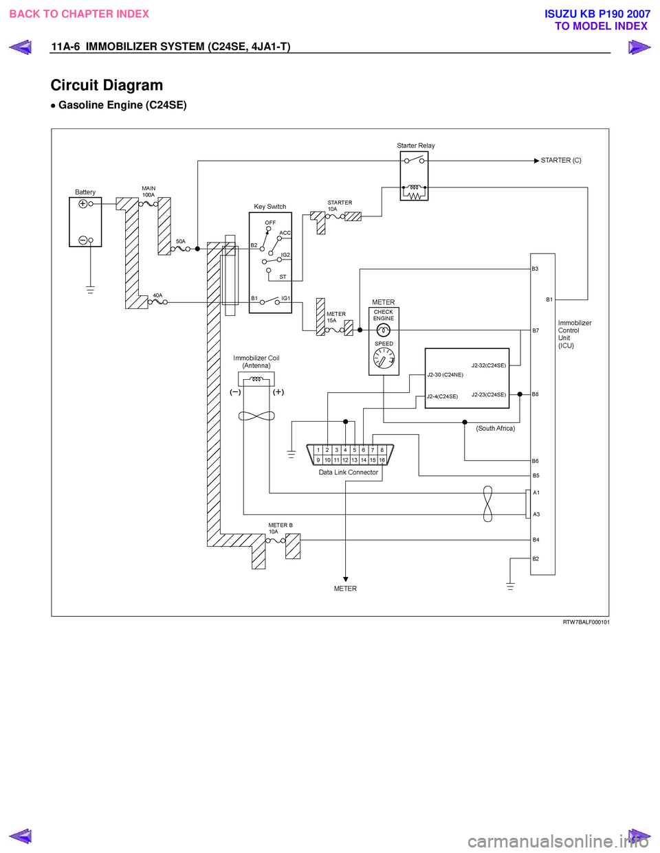
11A-6 IMMOBILIZER SYSTEM (C24SE, 4JA1-T)
Circuit Diagram
•
••
•
Gasoline Engine (C24SE)
RTW 7BALF000101
BACK TO CHAPTER INDEX TO MODEL INDEX
ISUZU KB P190 2007