Page 2444 of 6020
6E–274 ENGINE DRIVEABILITY AND EMISSIONS
5. Remove the fuel pressure regulator retaining screw.
6. Remove the fuel pressure regulator from fuel rail.
Installation Procedure 1. Insert the fuel pressure regulator into the fuel rail. 2. Install the fuel pressure regulator retaining bracket
and tighten with a screw.
3. Connect vacuum line onto the fuel pressure regulator.
4. Install the fuel pump relay.
5. Connect the negative battery cable.
6. Crank the engine until it starts. Cranking the engine may take longer than usual due to trapped air in the
fuel line.
7. Tighten the flare nut to 27 - 33 N·m (2.8 - 3.4 kgf·m).
BACK TO CHAPTER INDEX
TO MODEL INDEX
ISUZU KB P190 2007
Page 2445 of 6020

ENGINE DRIVEABILITY AND EMISSIONS 6E–275
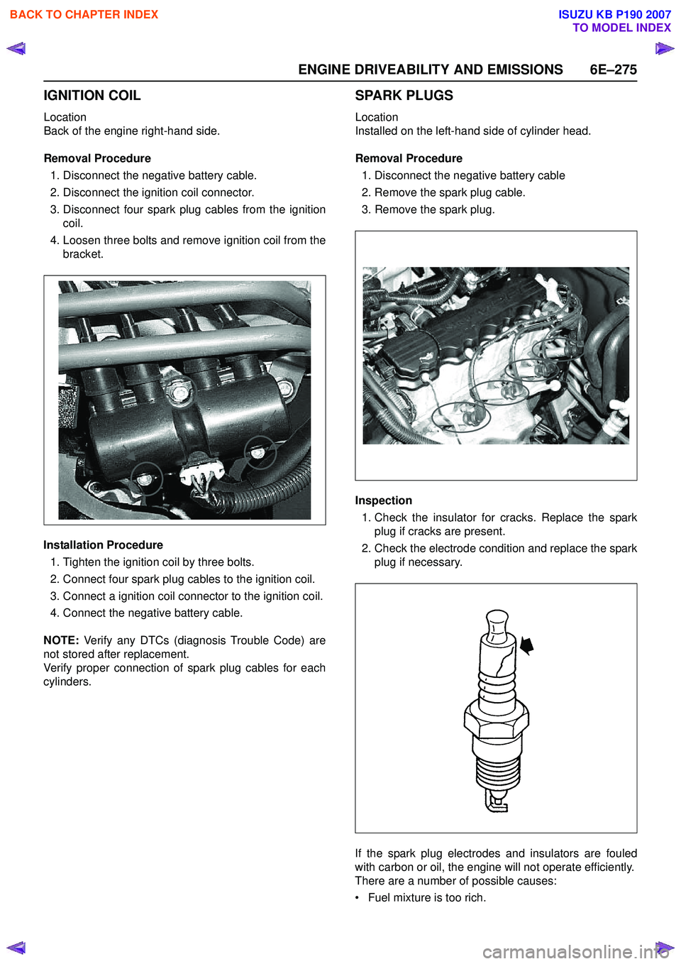
IGNITION COIL
Location
Back of the engine right-hand side.
Removal Procedure 1. Disconnect the negative battery cable.
2. Disconnect the ignition coil connector.
3. Disconnect four spark plug cables from the ignition coil.
4. Loosen three bolts and remove ignition coil from the bracket.
Installation Procedure 1. Tighten the ignition coil by three bolts.
2. Connect four spark plug cables to the ignition coil.
3. Connect a ignition coil connector to the ignition coil.
4. Connect the negative battery cable.
NOTE: Verify any DTCs (diagnosis Trouble Code) are
not stored after replacement.
Verify proper connection of spark plug cables for each
cylinders.
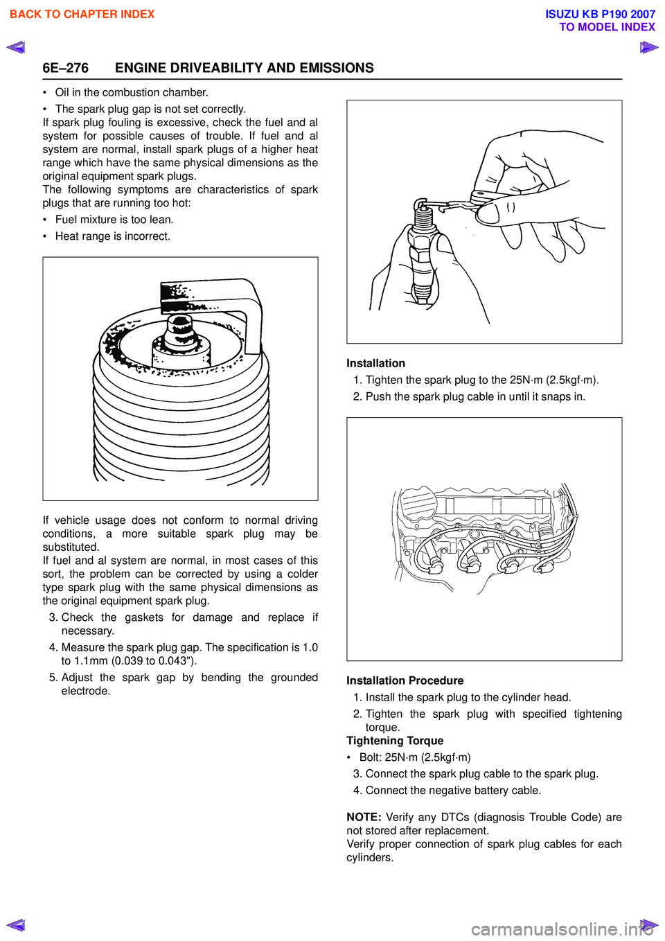
SPARK PLUGS
Location
Installed on the left-hand side of cylinder head.
Removal Procedure 1. Disconnect the negative battery cable
2. Remove the spark plug cable.
3. Remove the spark plug.
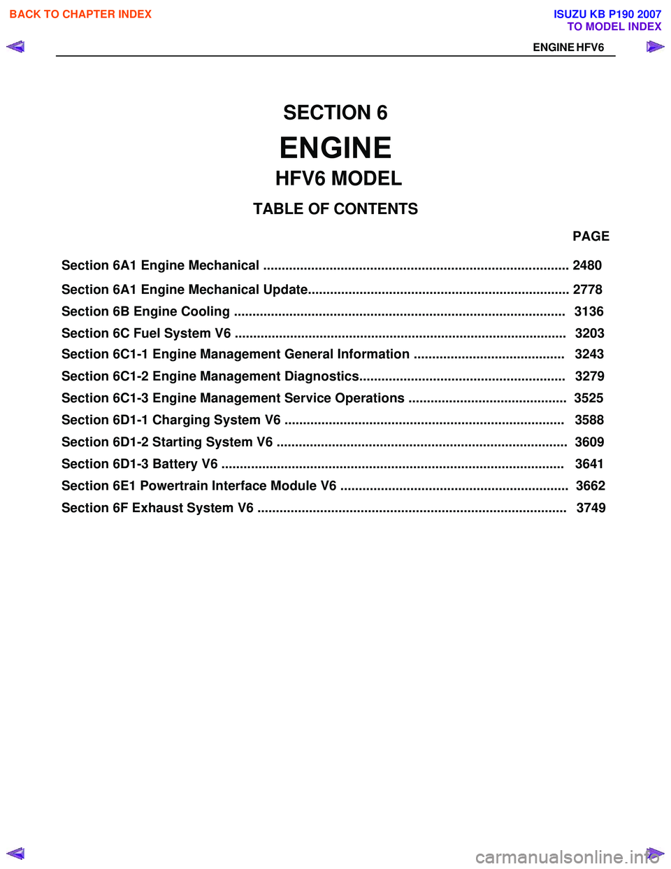
Inspection 1. Check the insulator for cracks. Replace the spark plug if cracks are present.
2. Check the electrode condition and replace the spark plug if necessary.
If the spark plug electrodes and insulators are fouled
with carbon or oil, the engine will not operate efficiently.
There are a number of possible causes:
• Fuel mixture is too rich.
BACK TO CHAPTER INDEX
TO MODEL INDEX
ISUZU KB P190 2007
Page 2446 of 6020

6E–276 ENGINE DRIVEABILITY AND EMISSIONS
• Oil in the combustion chamber.
• The spark plug gap is not set correctly.
If spark plug fouling is excessive, check the fuel and al
system for possible causes of trouble. If fuel and al
system are normal, install spark plugs of a higher heat
range which have the same physical dimensions as the
original equipment spark plugs.
The following symptoms are characteristics of spark
plugs that are running too hot:
• Fuel mixture is too lean.
• Heat range is incorrect.
If vehicle usage does not conform to normal driving
conditions, a more suitable spark plug may be
substituted.
If fuel and al system are normal, in most cases of this
sort, the problem can be corrected by using a colder
type spark plug with the same physical dimensions as
the original equipment spark plug.
3. Check the gaskets for damage and replace if necessary.
4. Measure the spark plug gap. The specification is 1.0 to 1.1mm (0.039 to 0.043").
5. Adjust the spark gap by bending the grounded electrode. Installation
1. Tighten the spark plug to the 25N·m (2.5kgf·m).
2. Push the spark plug cable in until it snaps in.
Installation Procedure 1. Install the spark plug to the cylinder head.
2. Tighten the spark plug with specified tightening torque.
Tightening Torque
• Bolt: 25N·m (2.5kgf·m) 3. Connect the spark plug cable to the spark plug.
4. Connect the negative battery cable.
NOTE: Verify any DTCs (diagnosis Trouble Code) are
not stored after replacement.
Verify proper connection of spark plug cables for each
cylinders.
BACK TO CHAPTER INDEX
TO MODEL INDEX
ISUZU KB P190 2007
Page 2456 of 6020
ENGINE EXHAUST 6F-7
Front Exhaust Pipe (W/O Catalytic
Converter)
Front Exhaust Pipe and Associated Parts
RTW 46F000101
Legend
1. Front Exhaust Pipe Fixing Nuts
2. Front Exhaust Pipe
3. Mid Exhaust Pipe Fixing Nuts
Removal
(2.4L)
1. Disconnect battery ground cable.
2. Raise the vehicle and support with suitable safety stands.
3. Remove the front exhaust pipe fixing nuts (1).
4. Remove mid pipe fixing nuts (3).
5. Remove front exhaust pipe (2).
Installation
1. Install front exhaust pipe (2) and tighten four nuts (1). Torque:
Nuts: 28 N ⋅
⋅⋅
⋅
m (2.9 kgf ⋅
⋅⋅
⋅
m)
2. Tighten two nuts (3). Torque: 43 N ⋅
⋅⋅
⋅
m (4.4 kgf ⋅
⋅⋅
⋅
m)
BACK TO CHAPTER INDEX
TO MODEL INDEX
ISUZU KB P190 2007
Page 2457 of 6020
6F-8 ENGINE EXHAUST
Mid Pipe
Mid Pipe and Associated Parts
RTW 46FSF000201
Legend
1. Mid Exhaust Pipe
2. Mid Exhaust Pipe Fixing Nuts
3. Exhaust Silencer Fixing Nuts
Removal
(2.4L)
1. Disconnect battery ground cable.
2. Raise the vehicle and support with suitable safety stands.
3. Remove mid pipe fixing nuts (2).
4. Remove exhaust silencer fixing nuts (3).
5. Remove the pipe.
Installation
1. Install mid exhaust pipe (1) and tighten four fixing nuts (2)(3) to the specified torque:
Torque:
Fixing nuts: 43 N ⋅
⋅⋅
⋅
m (4.4 kgf ⋅
⋅⋅
⋅
m)
BACK TO CHAPTER INDEX
TO MODEL INDEX
ISUZU KB P190 2007
Page 2458 of 6020
ENGINE EXHAUST 6F-9
Catalytic Converter (If applicable)
Catalytic Converter and Associated Parts
RTW 46FSF000301
Legend
1. Catalytic Converter
2. O
2 Sensor Converter
3. Front Pipe Fixing Nuts
4. Mid Pipe Fixing Nuts
Removal
(2.4L)
1. Disconnect battery ground cable.
2. Raise the vehicle and support with suitable safety stands.
3. Remove front pipe fixing nuts (3).
4. Remove mid pipe fixing nuts (4).
5. Remove the O
2 sensor connector (2).
6. Remove the front exhaust pipe with catalytic converter (1).
Installation
1. Install Catalytic Converter (1) and tighten four to the specified torque:
Torque:
Fixing nuts: 28 N ⋅
⋅⋅
⋅
m (2.9 kgf ⋅
⋅⋅
⋅
m)
2. Tight two nuts (4) Torque:
Nuts: 43 N ⋅
⋅⋅
⋅
m (4.4 kgf ⋅
⋅⋅
⋅
m)
3. Connect the O
2 sensor connector (2).
BACK TO CHAPTER INDEX
TO MODEL INDEX
ISUZU KB P190 2007
Page 2461 of 6020
6F-12 ENGINE EXHAUST
Exhaust Silencer
Exhaust Silencer and Associated Parts
RTW 46FMF000701
Legend
1. Exhaust Silencer
2. Exhaust Silencer Fixing Nuts
3. Rubber
Removal
(2.4L)
1. Disconnect battery ground cable.
2. Raise the vehicle and support with suitable safety stands.
3. Remove the damper rubber and nut (2)(3).
4. Remove exhaust silencer (1).
BACK TO CHAPTER INDEX
TO MODEL INDEX
ISUZU KB P190 2007
Page 2479 of 6020

Section 6A1 Engine Mechanical ................................................................................... 2480 PAGE
Section 6A1 Engine Mechanical Update....................................................................... 2778
Section 6C1-1 Engine Management General Information ......................................... 3243
Section 6C1-2 Engine Management Diagnostics........................................................ 3279
Section 6C1-3 Engine Management Service Operations ........................................... 3525
Section 6D1-1 Charging System V6 ............................................................................ 3588
SECTION 6
ENGINE
TA BLE OF CONTENTS
Section 6D1-3 Battery V6 ............................................................................................. 3641
Section 6E1 Powertrain Interface Module V6 .............................................................. 3662
HFV6 MODEL
ENGINE HFV6
Section 6B Engine Cooling .......................................................................................... 3136
Section 6C Fuel System V6 .......................................................................................... 3203
Section 6 D1-2 St art ing Syste m V 6 ............................................................................... 36 09
Section 6F Exhaust System V6 .................................................................................... 3749
BACK TO CHAPTER INDEX
TO MODEL INDEX
ISUZU KB P190 2007