2007 ISUZU KB P190 BATTERY
[x] Cancel search: BATTERYPage 2373 of 6020
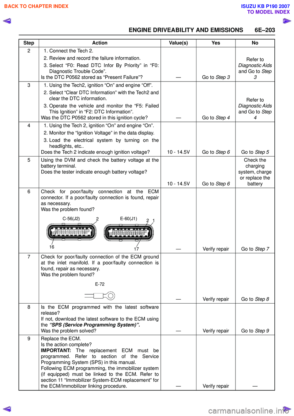
ENGINE DRIVEABILITY AND EMISSIONS 6E–203
2 1. Connect the Tech 2. 2. Review and record the failure information.
3. Select “F0: Read DTC Infor By Priority” in “F0: Diagnostic Trouble Code”.
Is the DTC P0562 stored as “Present Failure”? — Go to Step 3Refer to
Diagnostic Aids and Go to Step
3
3 1. Using the Tech2, ignition “On” and engine “Off”. 2. Select “Clear DTC Information” with the Tech2 andclear the DTC information.
3. Operate the vehicle and monitor the “F5: Failed This Ignition” in “F2: DTC Information”.
Was the DTC P0562 stored in this ignition cycle? — Go to Step 4Refer to
Diagnostic Aids and Go to Step
4
4 1. Using the Tech 2, ignition “On” and engine “On”. 2. Monitor the “Ignition Voltage” in the data display.
3. Load the electrical system by turning on the headlights, etc..
Does the Tech 2 indicate enough ignition voltage? 10 - 14.5V Go to Step 6Go to Step 5
5 Using the DVM and check the battery voltage at the battery terminal.
Does the tester indicate enough battery voltage?
10 - 14.5V Go to Step 6Check the
charging
system, charge or replace the battery
6 Check for poor/faulty connection at the ECM connector. If a poor/faulty connection is found, repair
as necessary.
Was the problem found?
— Verify repair Go to Step 7
7 Check for poor/faulty connection of the ECM ground at the inlet manifold. If a poor/faulty connection is
found, repair as necessary.
Was the problem found?
— Verify repair Go to Step 8
8 Is the ECM programmed with the latest software release?
If not, download the latest software to the ECM using
the “SPS (Service Programming System)”.
Was the problem solved? — Verify repair Go to Step 9
9 Replace the ECM. Is the action complete?
IMPORTANT: The replacement ECM must be
programmed. Refer to section of the Service
Programming System (SPS) in this manual.
Following ECM programming, the immobilizer system
(if equipped) must be linked to the ECM. Refer to
section 11 “Immobilizer System-ECM replacement” for
the ECM/Immobilizer linking procedure. — Verify repair —
Step
Action Value(s) Yes No
16
2
17
12
C-56(J2)
E-60(J1)
E-72
BACK TO CHAPTER INDEX
TO MODEL INDEX
ISUZU KB P190 2007
Page 2374 of 6020
6E–204 ENGINE DRIVEABILITY AND EMISSIONS
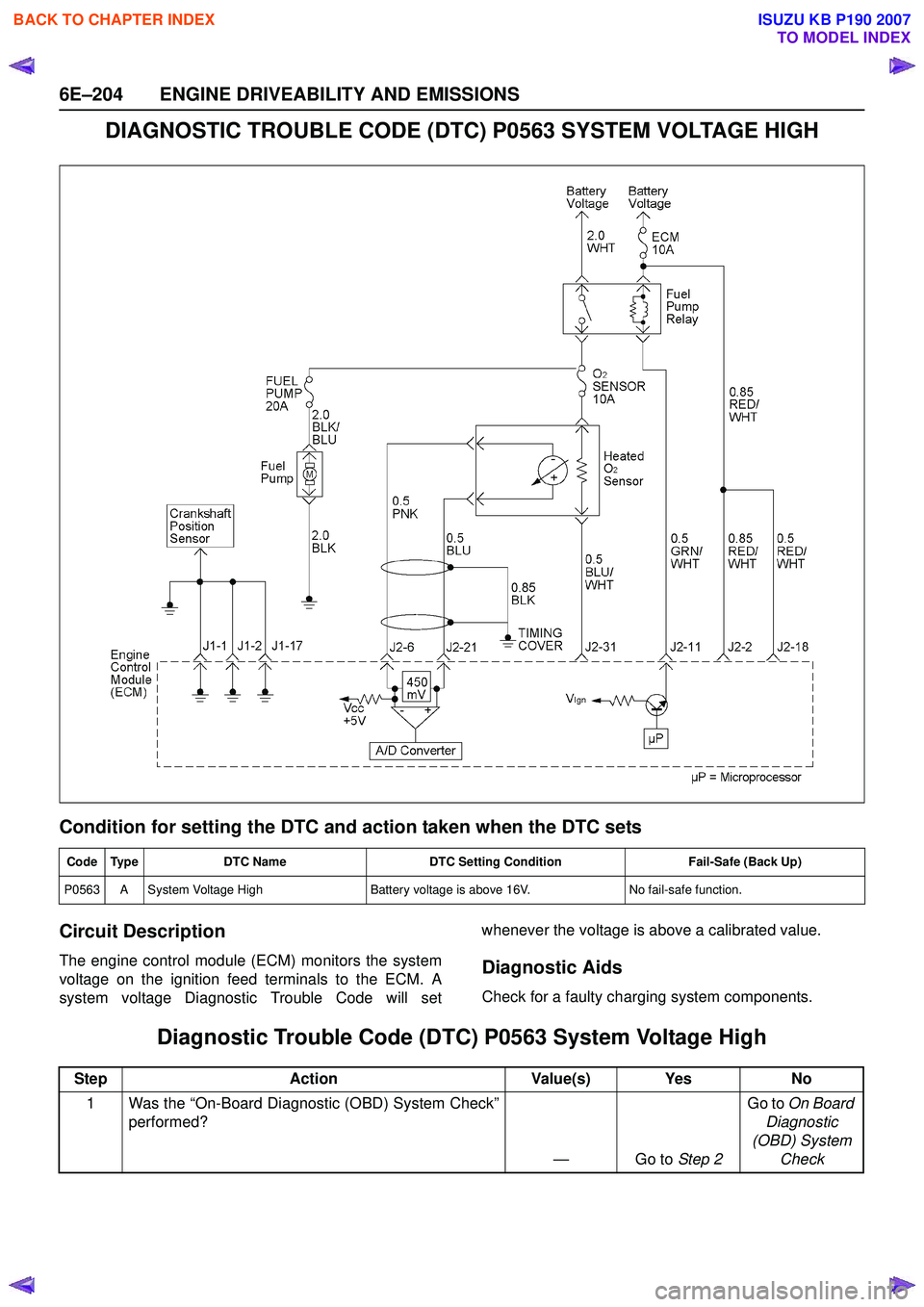
DIAGNOSTIC TROUBLE CODE (DTC) P0563 SYSTEM VOLTAGE HIGH
Condition for setting the DTC and action taken when the DTC sets
Circuit Description
The engine control module (ECM) monitors the system
voltage on the ignition feed terminals to the ECM. A
system voltage Diagnostic Trouble Code will set whenever the voltage is above a calibrated value.Diagnostic Aids
Check for a faulty charging system components.
Diagnostic Trouble Code (DTC) P0563 System Voltage High
Code Type
DTC Name DTC Setting Condition Fail-Safe (Back Up)
P0563 A System Voltage High Battery voltage is above 16V.No fail-safe function.
StepAction Value(s) Yes No
1 Was the “On-Board Diagnostic (OBD) System Check” performed?
—Go to Step 2Go to
On Board
Diagnostic
(OBD) System Check
BACK TO CHAPTER INDEX
TO MODEL INDEX
ISUZU KB P190 2007
Page 2375 of 6020
ENGINE DRIVEABILITY AND EMISSIONS 6E–205
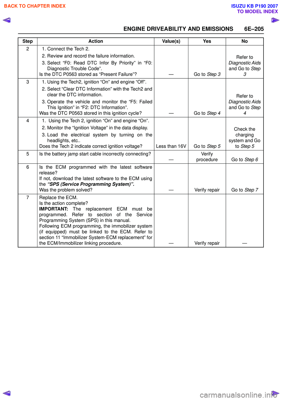
2 1. Connect the Tech 2. 2. Review and record the failure information.
3. Select “F0: Read DTC Infor By Priority” in “F0: Diagnostic Trouble Code”.
Is the DTC P0563 stored as “Present Failure”? — Go to Step 3Refer to
Diagnostic Aids and Go to Step
3
3 1. Using the Tech2, ignition “On” and engine “Off”. 2. Select “Clear DTC Information” with the Tech2 andclear the DTC information.
3. Operate the vehicle and monitor the “F5: Failed This Ignition” in “F2: DTC Information”.
Was the DTC P0563 stored in this ignition cycle? — Go to Step 4Refer to
Diagnostic Aids and Go to Step
4
4 1. Using the Tech 2, ignition “On” and engine “On”. 2. Monitor the “Ignition Voltage” in the data display.
3. Load the electrical system by turning on the headlights, etc..
Does the Tech 2 indicate correct ignition voltage? Less than 16V Go to Step 5Check the
charging
system and Go to Step 5
5 Is the battery jamp start cable incorrectly connecting? —Ve r if y
procedure Go to Step 6
6 Is the ECM programmed with the latest software release?
If not, download the latest software to the ECM using
the “SPS (Service Programming System)”.
Was the problem solved? — Verify repair Go to Step 7
7 Replace the ECM. Is the action complete?
IMPORTANT: The replacement ECM must be
programmed. Refer to section of the Service
Programming System (SPS) in this manual.
Following ECM programming, the immobilizer system
(if equipped) must be linked to the ECM. Refer to
section 11 “Immobilizer System-ECM replacement” for
the ECM/Immobilizer linking procedure. — Verify repair —
Step
Action Value(s) Yes No
BACK TO CHAPTER INDEX
TO MODEL INDEX
ISUZU KB P190 2007
Page 2403 of 6020
ENGINE DRIVEABILITY AND EMISSIONS 6E–233
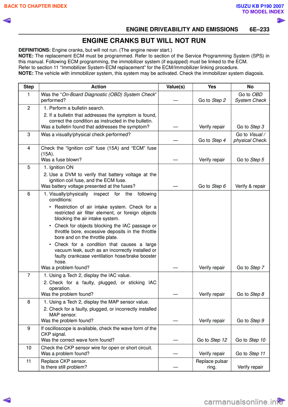
ENGINE CRANKS BUT WILL NOT RUN
DEFINITIONS: Engine cranks, but will not run. (The engine never start.)
NOTE: The replacement ECM must be programmed. Refer to section of the Service Programming System (SPS) in
this manual. Following ECM programming, the immobilizer system (if equipped) must be linked to the ECM.
Refer to section 11 “Immobilizer System-ECM replacement” for the ECM/Immobilizer linking procedure.
NOTE: The vehicle with immobilizer system, this system may be activated. Check the immobilizer system diagosis.
Step Action Value(s) Yes No
1 Was the “ On-Board Diagnostic (OBD) System Check ”
performed? — Go to Step 2Go to
OBD
System Check
2 1. Perform a bulletin search. 2. If a bulletin that addresses the symptom is found,correct the condition as instructed in the bulletin.
Was a bulletin found that addresses the symptom? — Verify repair Go to Step 3
3 Was a visually/physical check performed? —Go to Step 4Go to
Visual /
physical Check.
4 Check the “Ignition coil” fuse (15A) and “ECM” fuse (15A).
Was a fuse blown? — Verify repair Go to Step 5
5 1. Ignition ON 2. Use a DVM to verify that battery voltage at theignition coil fuse, and the ECM fuse.
Was battery voltage presented at the fuses? — Go to Step 6Verify & repair
6 1. Visually/physically inspect for the following conditions:
• Restriction of air intake system. Check for a restricted air filter element, or foreign objects
blocking the air intake system.
• Check for objects blocking the IAC passage or throttle bore, excessive deposits in the throttle
bore and on the throttle plate.
• Check for a condition that causes a large vacuum leak, such as an incorrectly installed or
faulty crankcase ventilation hose/brake booster
hose.
Was a problem found? — Verify repair Go to Step 7
7 1. Using a Tech 2, display the IAC value. 2. Check for a faulty, plugged, or sticking IACoperation.
Was the problem found? — Verify repair Go to Step 8
8 1. Using a Tech 2, display the MAP sensor value. 2. Check for a faulty, plugged, or incorrectly installedMAP sensor.
Was the problem found? — Verify repair Go to Step 9
9 If oscilloscope is available, check the wave form of the CKP signal.
Was the correct wave form found? — Go to Step 12Go to Step 10
10 Check the CKP sensor wire for open or short circuit. Was a problem found? — Verify repair Go to Step 11
11 Replace CKP sensor. Is there still problem? —Replace pulsar
ring. Verify repair
BACK TO CHAPTER INDEX
TO MODEL INDEX
ISUZU KB P190 2007
Page 2404 of 6020
6E–234 ENGINE DRIVEABILITY AND EMISSIONS
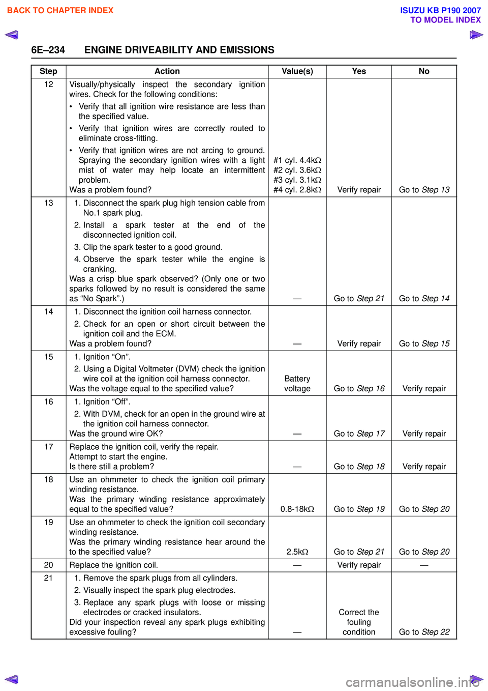
12 Visually/physically inspect the secondary ignitionwires. Check for the following conditions:
• Verify that all ignition wire resistance are less than the specified value.
• Verify that ignition wires are correctly routed to eliminate cross-fitting.
• Verify that ignition wires are not arcing to ground. Spraying the secondary ignition wires with a light
mist of water may help locate an intermittent
problem.
Was a problem found? #1 cyl. 4.4k
Ω
#2 cyl. 3.6k Ω
#3 cyl. 3.1k Ω
#4 cyl. 2.8k ΩVerify repair Go to Step 13
13 1. Disconnect the spark plug high tension cable from No.1 spark plug.
2. Install a spark tester at the end of the disconnected ignition coil.
3. Clip the spark tester to a good ground.
4. Observe the spark tester while the engine is cranking.
Was a crisp blue spark observed? (Only one or two
sparks followed by no result is considered the same
as “No Spark”.) — Go to Step 21Go to Step 14
14 1. Disconnect the ignition coil harness connector. 2. Check for an open or short circuit between theignition coil and the ECM.
Was a problem found? — Verify repair Go to Step 15
15 1. Ignition “On”. 2. Using a Digital Voltmeter (DVM) check the ignitionwire coil at the ignition coil harness connector.
Was the voltage equal to the specified value? Battery
voltage Go to Step 16Verify repair
16 1. Ignition “Off”. 2. With DVM, check for an open in the ground wire atthe ignition coil harness connector.
Was the ground wire OK? — Go to Step 17Verify repair
17 Replace the ignition coil, verify the repair. Attempt to start the engine.
Is there still a problem? — Go to Step 18Verify repair
18 Use an ohmmeter to check the ignition coil primary winding resistance.
Was the primary winding resistance approximately
equal to the specified value? 0.8-18kΩGo to Step 19 Go to Step 20
19 Use an ohmmeter to check the ignition coil secondary winding resistance.
Was the primary winding resistance hear around the
to the specified value? 2.5kΩ Go to Step 21 Go to Step 20
20 Replace the ignition coil. — Verify repair —
21 1. Remove the spark plugs from all cylinders. 2. Visually inspect the spark plug electrodes.
3. Replace any spark plugs with loose or missing electrodes or cracked insulators.
Did your inspection reveal any spark plugs exhibiting
excessive fouling? —Correct the
fouling
condition Go to Step 22
Step
Action Value(s) Yes No
BACK TO CHAPTER INDEX
TO MODEL INDEX
ISUZU KB P190 2007
Page 2431 of 6020
ENGINE DRIVEABILITY AND EMISSIONS 6E–261
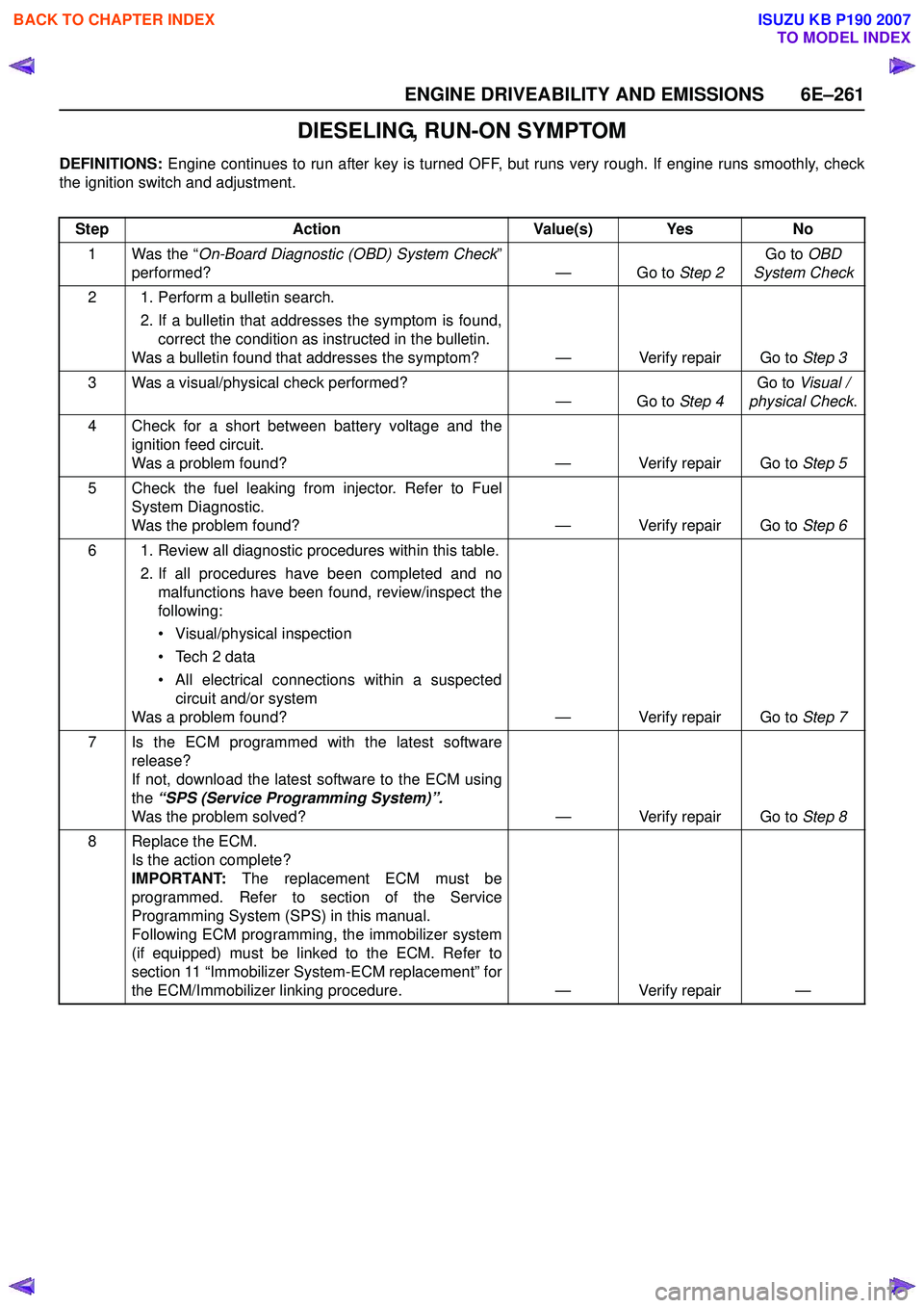
DIESELING, RUN-ON SYMPTOM
DEFINITIONS: Engine continues to run after key is turned OFF, but runs very rough. If engine runs smoothly, check
the ignition switch and adjustment.
Step Action Value(s) Yes No
1 Was the “ On-Board Diagnostic (OBD) System Check ”
performed? — Go to Step 2Go to
OBD
System Check
2 1. Perform a bulletin search. 2. If a bulletin that addresses the symptom is found,correct the condition as instructed in the bulletin.
Was a bulletin found that addresses the symptom? — Verify repair Go to Step 3
3 Was a visual/physical check performed? —Go to Step 4Go to
Visual /
physical Check .
4 Check for a short between battery voltage and the ignition feed circuit.
Was a problem found? — Verify repair Go to Step 5
5 Check the fuel leaking from injector. Refer to Fuel System Diagnostic.
Was the problem found? — Verify repair Go to Step 6
6 1. Review all diagnostic procedures within this table. 2. If all procedures have been completed and nomalfunctions have been found, review/inspect the
following:
• Visual/physical inspection
• Tech 2 data
• All electrical connections within a suspected circuit and/or system
Was a problem found? — Verify repair Go to Step 7
7 Is the ECM programmed with the latest software release?
If not, download the latest software to the ECM using
the “SPS (Service Programming System)”.
Was the problem solved? — Verify repair Go to Step 8
8 Replace the ECM. Is the action complete?
IMPORTANT: The replacement ECM must be
programmed. Refer to section of the Service
Programming System (SPS) in this manual.
Following ECM programming, the immobilizer system
(if equipped) must be linked to the ECM. Refer to
section 11 “Immobilizer System-ECM replacement” for
the ECM/Immobilizer linking procedure. — Verify repair —
BACK TO CHAPTER INDEX
TO MODEL INDEX
ISUZU KB P190 2007
Page 2434 of 6020
6E–264 ENGINE DRIVEABILITY AND EMISSIONS
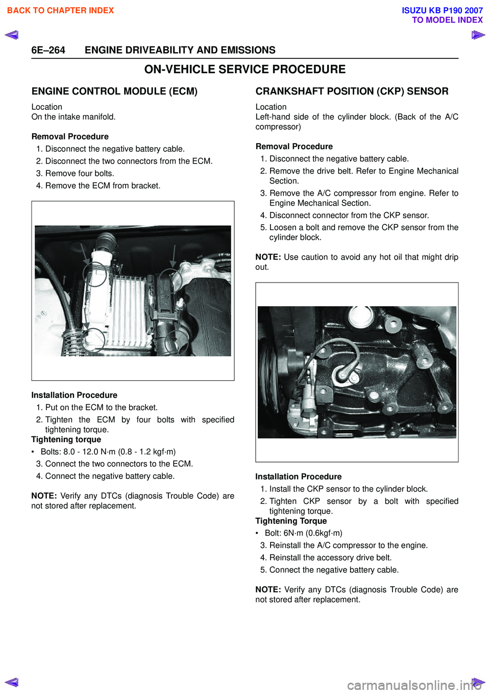
ON-VEHICLE SERVICE PROCEDURE
ENGINE CONTROL MODULE (ECM)
Location
On the intake manifold.
Removal Procedure 1. Disconnect the negative battery cable.
2. Disconnect the two connectors from the ECM.
3. Remove four bolts.
4. Remove the ECM from bracket.
Installation Procedure 1. Put on the ECM to the bracket.
2. Tighten the ECM by four bolts with specified tightening torque.
Tightening torque
• Bolts: 8.0 - 12.0 N·m (0.8 - 1.2 kgf·m) 3. Connect the two connectors to the ECM.
4. Connect the negative battery cable.
NOTE: Verify any DTCs (diagnosis Trouble Code) are
not stored after replacement.
CRANKSHAFT POSITION (CKP) SENSOR
Location
Left-hand side of the cylinder block. (Back of the A/C
compressor)
Removal Procedure 1. Disconnect the negative battery cable.
2. Remove the drive belt. Refer to Engine Mechanical Section.
3. Remove the A/C compressor from engine. Refer to Engine Mechanical Section.
4. Disconnect connector from the CKP sensor.
5. Loosen a bolt and remove the CKP sensor from the cylinder block.
NOTE: Use caution to avoid any hot oil that might drip
out.
Installation Procedure 1. Install the CKP sensor to the cylinder block.
2. Tighten CKP sensor by a bolt with specified tightening torque.
Tightening Torque
• Bolt: 6N·m (0.6kgf·m)
3. Reinstall the A/C compressor to the engine.
4. Reinstall the accessory drive belt.
5. Connect the negative battery cable.
NOTE: Verify any DTCs (diagnosis Trouble Code) are
not stored after replacement.
BACK TO CHAPTER INDEX
TO MODEL INDEX
ISUZU KB P190 2007
Page 2435 of 6020
ENGINE DRIVEABILITY AND EMISSIONS 6E–265
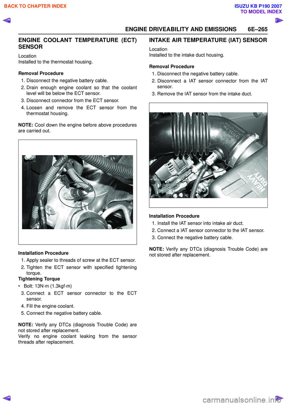
ENGINE COOLANT TEMPERATURE (ECT)
SENSOR
Location
Installed to the thermostat housing.
Removal Procedure 1. Disconnect the negative battery cable.
2. Drain enough engine coolant so that the coolant level will be below the ECT sensor.
3. Disconnect connector from the ECT sensor.
4. Loosen and remove the ECT sensor from the thermostat housing.
NOTE: Cool down the engine before above procedures
are carried out.
Installation Procedure
1. Apply sealer to threads of screw at the ECT sensor.
2. Tighten the ECT sensor with specified tightening torque.
Tightening Torque
• Bolt: 13N·m (1.3kgf·m)
3. Connect a ECT sensor connector to the ECT sensor.
4. Fill the engine coolant.
5. Connect the negative battery cable.
NOTE: Verify any DTCs (diagnosis Trouble Code) are
not stored after replacement.
Verify no engine coolant leaking from the sensor
threads after replacement.
INTAKE AIR TEMPERATURE (IAT) SENSOR
Location
Installed to the intake duct housing.
Removal Procedure 1. Disconnect the negative battery cable.
2. Disconnect a IAT sensor connector from the IAT sensor.
3. Remove the IAT sensor from the intake duct.
Installation Procedure 1. Install the IAT sensor into intake air duct.
2. Connect a IAT sensor connector to the IAT sensor.
3. Connect the negative battery cable.
NOTE: Verify any DTCs (diagnosis Trouble Code) are
not stored after replacement.
BACK TO CHAPTER INDEX
TO MODEL INDEX
ISUZU KB P190 2007