Page 1520 of 6020

6A-160 ENGINE MECHANICAL (4JK1/4JJ1)
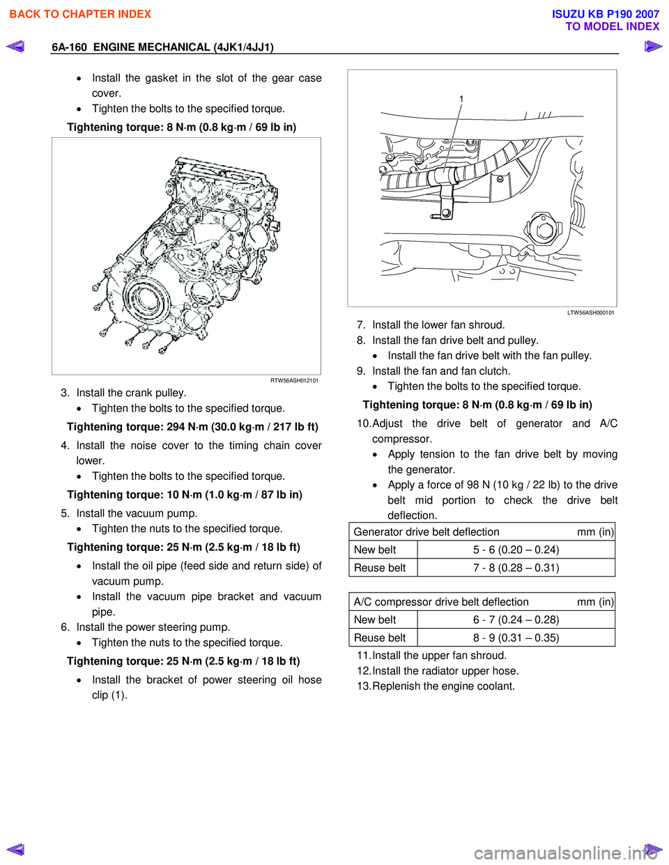
• Install the gasket in the slot of the gear case
cover.
• Tighten the bolts to the specified torque.
Tightening torque: 8 N ⋅
⋅⋅
⋅
m (0.8 kg ⋅
⋅⋅
⋅
m / 69 lb in)
RTW 56ASH012101
3. Install the crank pulley.
• Tighten the bolts to the specified torque.
Tightening torque: 294 N ⋅
⋅⋅
⋅
m (30.0 kg ⋅
⋅⋅
⋅
m / 217 lb ft)
4. Install the noise cover to the timing chain cove
r
lower.
• Tighten the bolts to the specified torque.
Tightening torque: 10 N ⋅
⋅⋅
⋅
m (1.0 kg ⋅
⋅⋅
⋅
m / 87 lb in)
5. Install the vacuum pump. • Tighten the nuts to the specified torque.
Tightening torque: 25 N ⋅
⋅⋅
⋅
m (2.5 kg ⋅
⋅⋅
⋅
m / 18 lb ft)
• Install the oil pipe (feed side and return side) o
f
vacuum pump.
• Install the vacuum pipe bracket and vacuum
pipe.
6. Install the power steering pump. • Tighten the nuts to the specified torque.
Tightening torque: 25 N ⋅
⋅⋅
⋅
m (2.5 kg ⋅
⋅⋅
⋅
m / 18 lb ft)
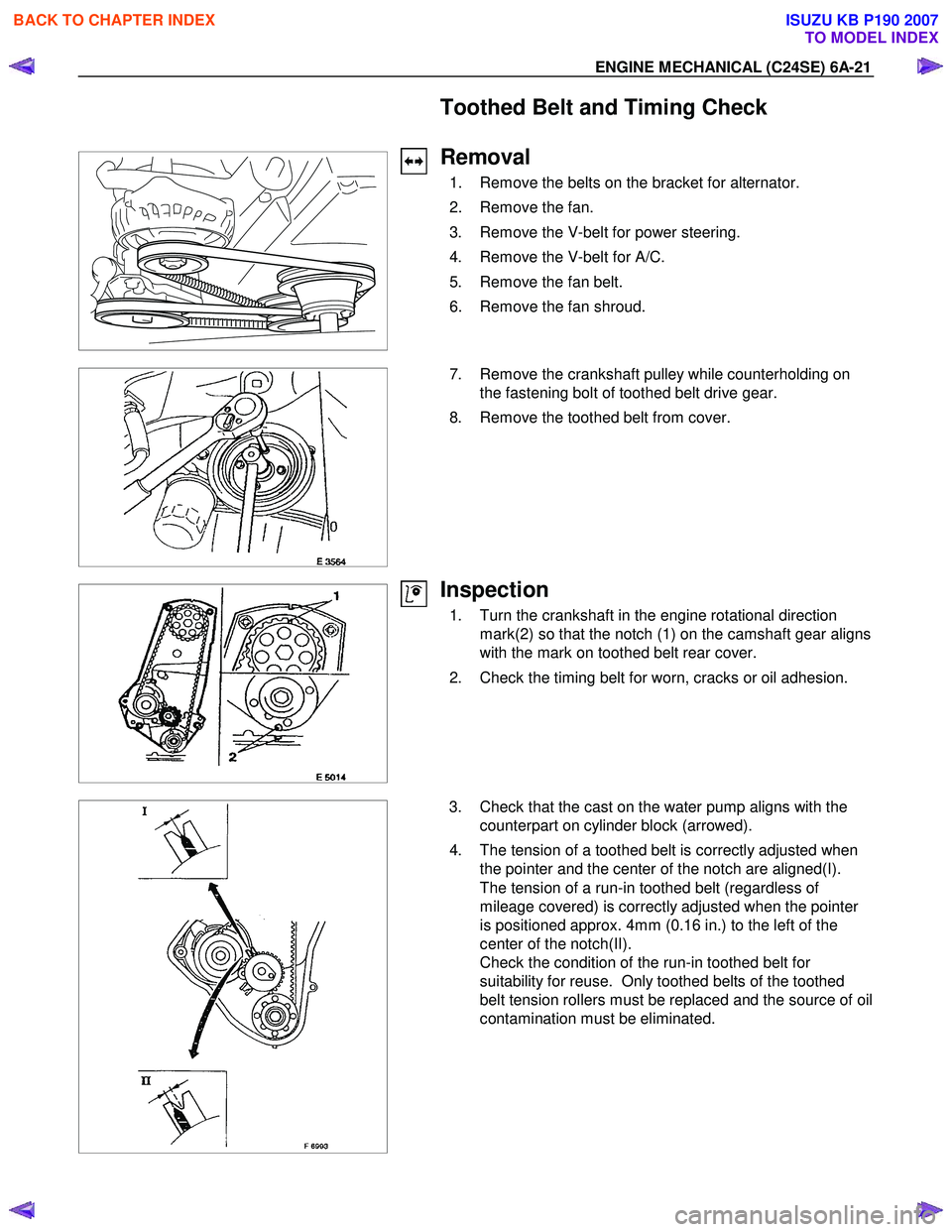
• Install the bracket of power steering oil hose
clip (1).
LTW 56ASH000101
7. Install the lower fan shroud.
8. Install the fan drive belt and pulley. • Install the fan drive belt with the fan pulley.
9. Install the fan and fan clutch. • Tighten the bolts to the specified torque.
Tightening torque: 8 N ⋅
⋅⋅
⋅
m (0.8 kg ⋅
⋅⋅
⋅
m / 69 lb in)
10.
Adjust the drive belt of generator and A/C
compressor.
• Apply tension to the fan drive belt by moving
the generator.
•
Apply a force of 98 N (10 kg / 22 lb) to the drive
belt mid portion to check the drive belt
deflection.
Generator drive belt deflection mm (in)
New belt 5 - 6 (0.20 – 0.24)
Reuse belt 7 - 8 (0.28 – 0.31)
A/C compressor drive belt deflection mm (in)
New belt 6 - 7 (0.24 – 0.28)
Reuse belt 8 - 9 (0.31 – 0.35)
11. Install the upper fan shroud.
12. Install the radiator upper hose.
13. Replenish the engine coolant.
BACK TO CHAPTER INDEX
TO MODEL INDEX
ISUZU KB P190 2007
Page 2035 of 6020

ENGINE MECHANICAL (C24SE) 6A-21
Toothed Belt and Timing Check
Removal
1. Remove the belts on the bracket for alternator.
2. Remove the fan.
3. Remove the V-belt for power steering.
4. Remove the V-belt for A/C.
5. Remove the fan belt.
6. Remove the fan shroud.
7. Remove the crankshaft pulley while counterholding on
the fastening bolt of toothed belt drive gear.
8. Remove the toothed belt from cover.
Inspection
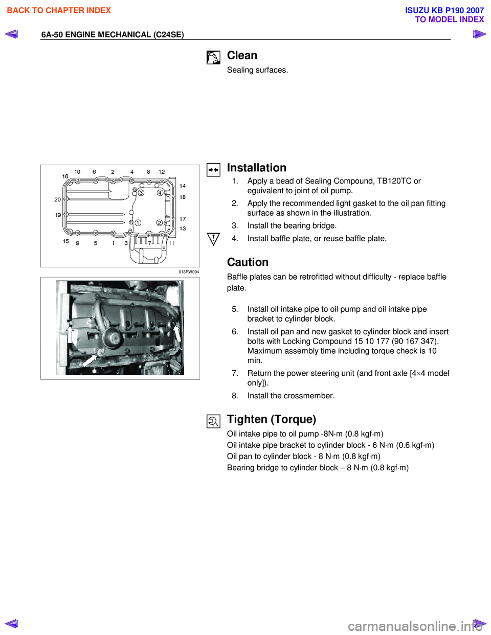
1. Turn the crankshaft in the engine rotational direction mark(2) so that the notch (1) on the camshaft gear aligns
with the mark on toothed belt rear cover.
2. Check the timing belt for worn, cracks or oil adhesion.
3. Check that the cast on the water pump aligns with the counterpart on cylinder block (arrowed).
4. The tension of a toothed belt is correctly adjusted when the pointer and the center of the notch are aligned(I).
The tension of a run-in toothed belt (regardless of
mileage covered) is correctly adjusted when the pointer
is positioned approx. 4mm (0.16 in.) to the left of the
center of the notch(II).
Check the condition of the run-in toothed belt for
suitability for reuse. Only toothed belts of the toothed
belt tension rollers must be replaced and the source of oil
contamination must be eliminated.
BACK TO CHAPTER INDEX
TO MODEL INDEX
ISUZU KB P190 2007
Page 2036 of 6020
6A-22 ENGINE MECHANICAL (C24SE)
Installation
1. Install the toothed belt to the cover.
2. Install the crankshaft pulley while counterholding on the fastening bolt of toothed belt drive gear.
3. Install the fan shroud.
Tighten(Torque)
Crankshaft pulley bolts - 20 N ⋅m (2.1 kgf ⋅m)
4. Install the fan belt
5. Install the V-belt for A/C.
6. Install the V-belt for power steering.
7. Install the fan.
8. Install the belts on the bracket for alternator.
BACK TO CHAPTER INDEX
TO MODEL INDEX
ISUZU KB P190 2007
Page 2038 of 6020
6A-24 ENGINE MECHANICAL (C24SE)
Toothed Belt, Replace
(Engine with toothed belt tension
roller)
Removal
1. Remove the belts on the bracket for alternator.
2. Remove the fan.
3. Remove the V-belt for power steering.
4. Remove the V-belt for A/C.
5. Remove the fan belt.
6. Remove the fan shroud.
7. Remove the crankshaft pulley while counterholding on
the fastening bolt of toothed belt drive gear.
8. Remove the toothed belt from cover.
Adjust
Turn the crankshaft in the engine rotational direction to
mark(2).
Align markings on toothed belt and on toothed belt rear cover.
Simultaneously, notch (1) on camshaft gear must align with the
mark on toothed belt rear cover.
Turn the crankshaft slowly and smoothly.
BACK TO CHAPTER INDEX
TO MODEL INDEX
ISUZU KB P190 2007
Page 2039 of 6020
ENGINE MECHANICAL (C24SE) 6A-25
Adjust
Loosen the fastening bolt of the toothed belt tension roller and
turn the adjustment eccentric in the direction of arrow
(clockwise) until pointer (1) comes to the left stop.
Remove the toothed belt.
Installation
1. Install a new toothed belt while keeping tension side taut.
Adjust
Toothed belt tension - see operation " Toothed Belt Tension".
2. Install the toothed belt to the cover.
3. Install the crankshaft pulley while counterholding on the fastening bolt of toothed belt drive gear.
4. Install the fan shroud.
5. Install the fan belt.
6. Install the V-belt for A/C.
7. Install the V-belt for power steering.
8. Install the fan.
9. Install the belts to the bracket for alternator.
BACK TO CHAPTER INDEX
TO MODEL INDEX
ISUZU KB P190 2007
Page 2063 of 6020
ENGINE MECHANICAL (C24SE) 6A-49
Reassembly
Reassemble clutch assembly.
Disassembly
Disassemble clutch assembly to flywheel using 5-8840-2634-0
Torque Angle-Method
Clutch assembly to flywheel-17.6Nm/1.8 kgf �xm.
RTW 46ASH002801
Oil Pan and Bearing Bridge
Removal
1. Remove the crossmember.
2. Shift downward the power steering unit (and front axle [4 ×4 model only]).
3. Loosen fixing bolts.
4. Remove oil pan from oil pump and cylinder block.
5. Remove oil intake pipe, oil intake pipe bracket, and oil baffle plate.
6. Remove the bearing bridge.
BACK TO CHAPTER INDEX
TO MODEL INDEX
ISUZU KB P190 2007
Page 2064 of 6020

6A-50 ENGINE MECHANICAL (C24SE)
Clean
Sealing surfaces.
013RW 004
Installation
1. Apply a bead of Sealing Compound, TB120TC or eguivalent to joint of oil pump.
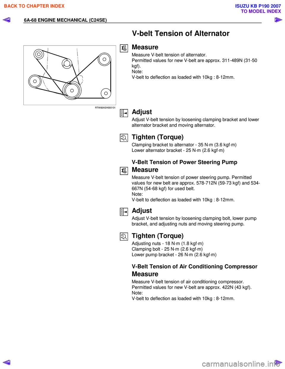
2. Apply the recommended light gasket to the oil pan fitting surface as shown in the illustration.
3. Install the bearing bridge.
4. Install baffle plate, or reuse baffle plate.
Caution
Baffle plates can be retrofitted without difficulty - replace baffle
plate.
5. Install oil intake pipe to oil pump and oil intake pipe bracket to cylinder block.
6. Install oil pan and new gasket to cylinder block and insert bolts with Locking Compound 15 10 177 (90 167 347).
Maximum assembly time including torque check is 10
min.
7. Return the power steering unit (and front axle [4 ×4 model
only]).
8. Install the crossmember.
Tighten (Torque)
Oil intake pipe to oil pump -8N ⋅m (0.8 kgf ⋅m)
Oil intake pipe bracket to cylinder block - 6 N ⋅m (0.6 kgf ⋅m)
Oil pan to cylinder block - 8 N ⋅m (0.8 kgf ⋅m)
Bearing bridge to cylinder block – 8 N ⋅m (0.8 kgf ⋅m)
BACK TO CHAPTER INDEX
TO MODEL INDEX
ISUZU KB P190 2007
Page 2082 of 6020

6A-68 ENGINE MECHANICAL (C24SE)
V-belt Tension of Alternator
RTW 66ASH000101
Measure
Measure V-belt tension of alternator.
Permitted values for new V-belt are approx. 311-489N (31-50
kgf).
Note:
V-belt to deflection as loaded with 10kg : 8-12mm.
Adjust
Adjust V-belt tension by loosening clamping bracket and lower
alternator bracket and moving alternator.
Tighten (Torque)
Clamping bracket to alternator - 35 N ⋅m (3.6 kgf ⋅m)
Lower alternator bracket - 25 N ⋅m (2.6 kgf ⋅m)
V-Belt Tension of Power Steering Pump
Measure
Measure V-belt tension of power steering pump. Permitted
values for new belt are approx. 578-712N (59-73 kgf) and 534-
667N (54-68 kgf) for used belt.
Note:
V-belt to deflection as loaded with 10kg : 8-12mm.
Adjust
Adjust V-belt tension by loosening clamping bolt, lower pump
bracket, and adjusting nuts and moving steering pump.
Tighten (Torque)
Adjusting nuts - 18 N ⋅m (1.8 kgf ⋅m)
Clamping bolt - 25 N ⋅m (2.6 kgf ⋅m)
Lower pump bracket - 26 N ⋅m (2.6 kgf ⋅m)
V-Belt Tension of Air Conditioning Compressor
Measure
Measure V-belt tension of air conditioning compressor.
Permitted values for new V-belt are approx. 422N (43 kgf).
Note:
V-belt to deflection as loaded with 10kg : 8-12mm.
BACK TO CHAPTER INDEX
TO MODEL INDEX
ISUZU KB P190 2007