2007 ISUZU KB P190 Harness
[x] Cancel search: HarnessPage 1775 of 6020
6E-158 ENGINE CONTROL SYSTEM (4JK1/4JJ1)
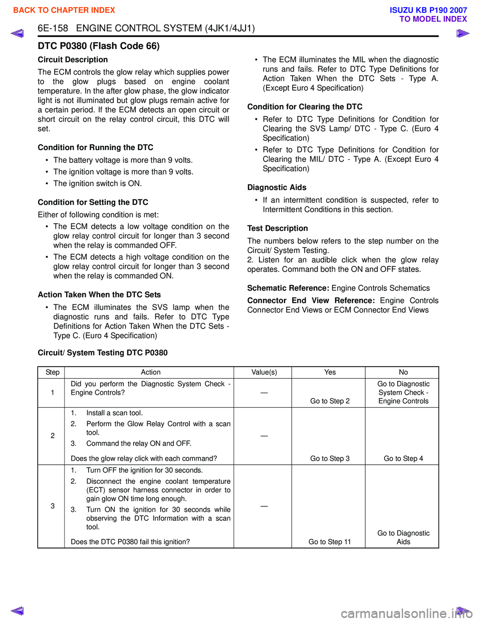
DTC P0380 (Flash Code 66)
Circuit Description
The ECM controls the glow relay which supplies power
to the glow plugs based on engine coolant
temperature. In the after glow phase, the glow indicator
light is not illuminated but glow plugs remain active for
a certain period. If the ECM detects an open circuit or
short circuit on the relay control circuit, this DTC will
set.
Condition for Running the DTC • The battery voltage is more than 9 volts.
• The ignition voltage is more than 9 volts.
• The ignition switch is ON.
Condition for Setting the DTC
Either of following condition is met: • The ECM detects a low voltage condition on the glow relay control circuit for longer than 3 second
when the relay is commanded OFF.
• The ECM detects a high voltage condition on the glow relay control circuit for longer than 3 second
when the relay is commanded ON.
Action Taken When the DTC Sets • The ECM illuminates the SVS lamp when the diagnostic runs and fails. Refer to DTC Type
Definitions for Action Taken When the DTC Sets -
Type C. (Euro 4 Specification) • The ECM illuminates the MIL when the diagnostic
runs and fails. Refer to DTC Type Definitions for
Action Taken When the DTC Sets - Type A.
(Except Euro 4 Specification)
Condition for Clearing the DTC • Refer to DTC Type Definitions for Condition for Clearing the SVS Lamp/ DTC - Type C. (Euro 4
Specification)
• Refer to DTC Type Definitions for Condition for Clearing the MIL/ DTC - Type A. (Except Euro 4
Specification)
Diagnostic Aids • If an intermittent condition is suspected, refer to Intermittent Conditions in this section.
Test Description
The numbers below refers to the step number on the
Circuit/ System Testing.
2. Listen for an audible click when the glow relay
operates. Command both the ON and OFF states.
Schematic Reference: Engine Controls Schematics
Connector End View Reference: Engine Controls
Connector End Views or ECM Connector End Views
Circuit/ System Testing DTC P0380
Step Action Value(s)Yes No
1 Did you perform the Diagnostic System Check -
Engine Controls? —
Go to Step 2 Go to Diagnostic
System Check -
Engine Controls
2 1. Install a scan tool.
2. Perform the Glow Relay Control with a scan tool.
3. Command the relay ON and OFF.
Does the glow relay click with each command? —
Go to Step 3 Go to Step 4
3 1. Turn OFF the ignition for 30 seconds.
2. Disconnect the engine coolant temperature (ECT) sensor harness connector in order to
gain glow ON time long enough.
3. Turn ON the ignition for 30 seconds while observing the DTC Information with a scan
tool.
Does the DTC P0380 fail this ignition? —
Go to Step 11 Go to Diagnostic
Aids
BACK TO CHAPTER INDEX
TO MODEL INDEX
ISUZU KB P190 2007
Page 1776 of 6020

ENGINE CONTROL SYSTEM (4JK1/4JJ1) 6E-159
41. Turn OFF the ignition.
2. Replace the glow relay with the starter relay or replace with a known good relay.
3. Perform the Glow Relay Control with a scan tool.
4. Command the relay ON and OFF.
Does the glow relay click with each command? —
Go to Step 8 Go to Step 5
5 1. Turn OFF the ignition.
2. Remove the glow relay.
3. Turn ON the ignition, with the engine OFF.
4. Probe the ignition voltage feed circuit of the relay coil side (pin 2 of X-5) with a test lamp
that is connected to a known good ground.
Does the test lamp illuminate? —
Go to Step 6 Go to Step 7
6 1. Test the control circuit between the ECM (pin
37 of C-58) and the relay (pin 3 of X-5) for the
following conditions:
• An open circuit
• A short to ground
• A short to battery or ignition voltage
2. Repair the circuit(s) as necessary.
Did you find and correct the condition? —
Go to Step 12 Go to Step 9
7 Repair the open circuit or high resistance between
the Engine (10A) fuse and the glow relay coil side
(pin 2 of X-5). Check the Engine (10A) fuse first.
Did you complete the repair? —
Go to Step 12
—
81. Remove the glow relay.
2. Inspect for an intermittent and for a poor connection on each relay terminal.
3. Repair the connection(s) as necessary.
Did you find and correct the condition? —
Go to Step 12 Go to Step 10
9 1. Turn OFF the ignition.
2. Disconnect the ECM harness connector.
3. Inspect for an intermittent and for a poor connection at the harness connector of the
ECM (pin 37 of C-58).
4. Repair the connection(s) as necessary.
Did you find and correct the condition? —
Go to Step 12 Go to Step 11
10 Replace the glow relay.
Did you complete the replacement? —
Go to Step 12
—
11Important:
Replacement ECM must be
programmed and learned.
Replace the ECM. Refer to ECM Replacement.
Did you complete the replacement? —
Go to Step 12
—
Step Action Value(s)Yes No
BACK TO CHAPTER INDEX
TO MODEL INDEX
ISUZU KB P190 2007
Page 1777 of 6020
6E-160 ENGINE CONTROL SYSTEM (4JK1/4JJ1)
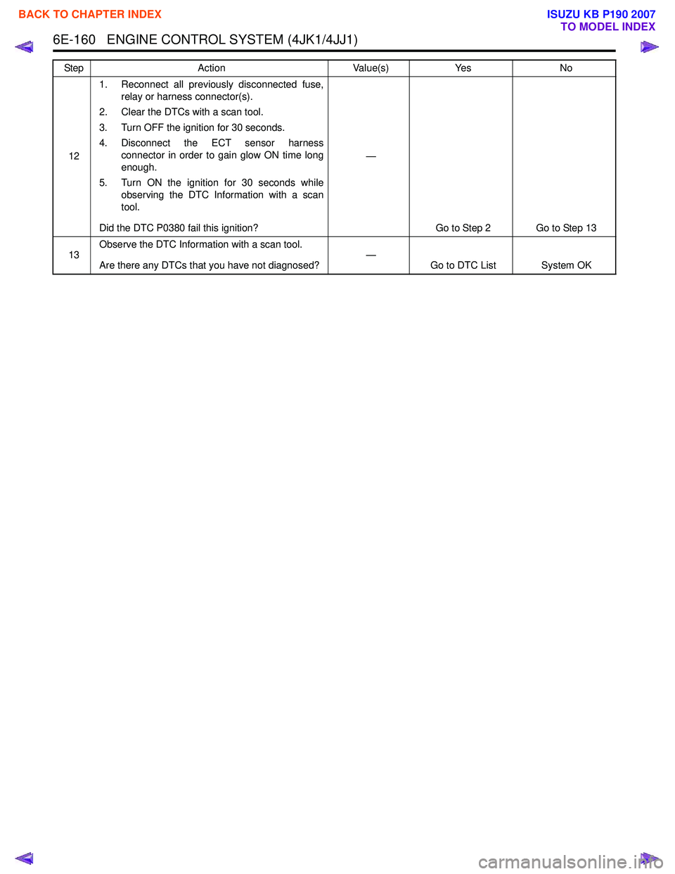
121. Reconnect all previously disconnected fuse,
relay or harness connector(s).
2. Clear the DTCs with a scan tool.
3. Turn OFF the ignition for 30 seconds.
4. Disconnect the ECT sensor harness connector in order to gain glow ON time long
enough.
5. Turn ON the ignition for 30 seconds while observing the DTC Information with a scan
tool.
Did the DTC P0380 fail this ignition? —
Go to Step 2 Go to Step 13
13 Observe the DTC Information with a scan tool.
Are there any DTCs that you have not diagnosed? —
Go to DTC List System OK
Step
Action Value(s)Yes No
BACK TO CHAPTER INDEX
TO MODEL INDEX
ISUZU KB P190 2007
Page 1779 of 6020
6E-162 ENGINE CONTROL SYSTEM (4JK1/4JJ1)
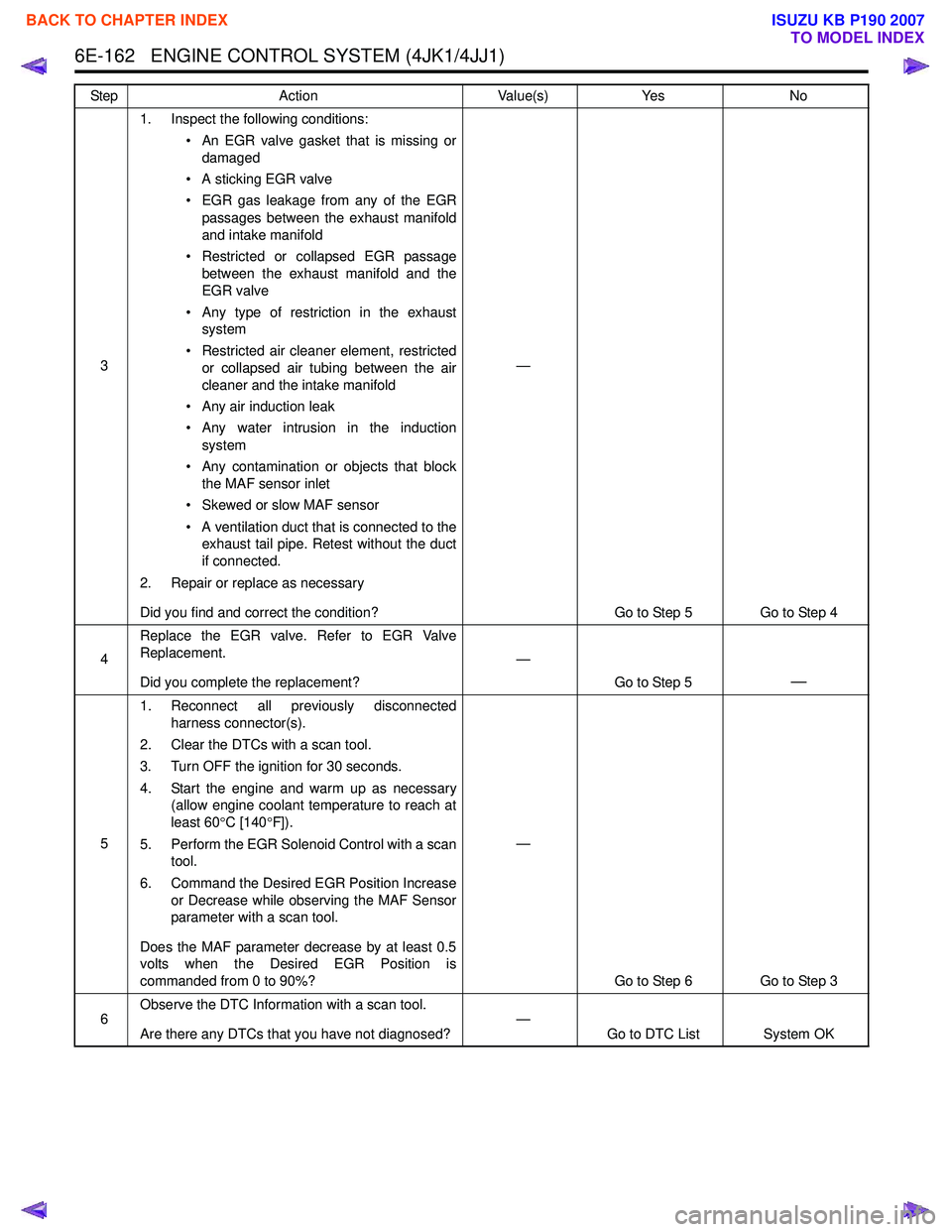
31. Inspect the following conditions:
• An EGR valve gasket that is missing ordamaged
• A sticking EGR valve
• EGR gas leakage from any of the EGR passages between the exhaust manifold
and intake manifold
• Restricted or collapsed EGR passage between the exhaust manifold and the
EGR valve
• Any type of restriction in the exhaust system
• Restricted air cleaner element, restricted or collapsed air tubing between the air
cleaner and the intake manifold
• Any air induction leak
• Any water intrusion in the induction system
• Any contamination or objects that block the MAF sensor inlet
• Skewed or slow MAF sensor
• A ventilation duct that is connected to the exhaust tail pipe. Retest without the duct
if connected.
2. Repair or replace as necessary
Did you find and correct the condition? —
Go to Step 5 Go to Step 4
4 Replace the EGR valve. Refer to EGR Valve
Replacement.
Did you complete the replacement? —
Go to Step 5
—
51. Reconnect all previously disconnected
harness connector(s).
2. Clear the DTCs with a scan tool.
3. Turn OFF the ignition for 30 seconds.
4. Start the engine and warm up as necessary (allow engine coolant temperature to reach at
least 60 °C [140 °F]).
5. Perform the EGR Solenoid Control with a scan tool.
6. Command the Desired EGR Position Increase or Decrease while observing the MAF Sensor
parameter with a scan tool.
Does the MAF parameter decrease by at least 0.5
volts when the Desired EGR Position is
commanded from 0 to 90%? —
Go to Step 6 Go to Step 3
6 Observe the DTC Information with a scan tool.
Are there any DTCs that you have not diagnosed? —
Go to DTC List System OK
Step
Action Value(s)Yes No
BACK TO CHAPTER INDEX
TO MODEL INDEX
ISUZU KB P190 2007
Page 1780 of 6020
ENGINE CONTROL SYSTEM (4JK1/4JJ1) 6E-163
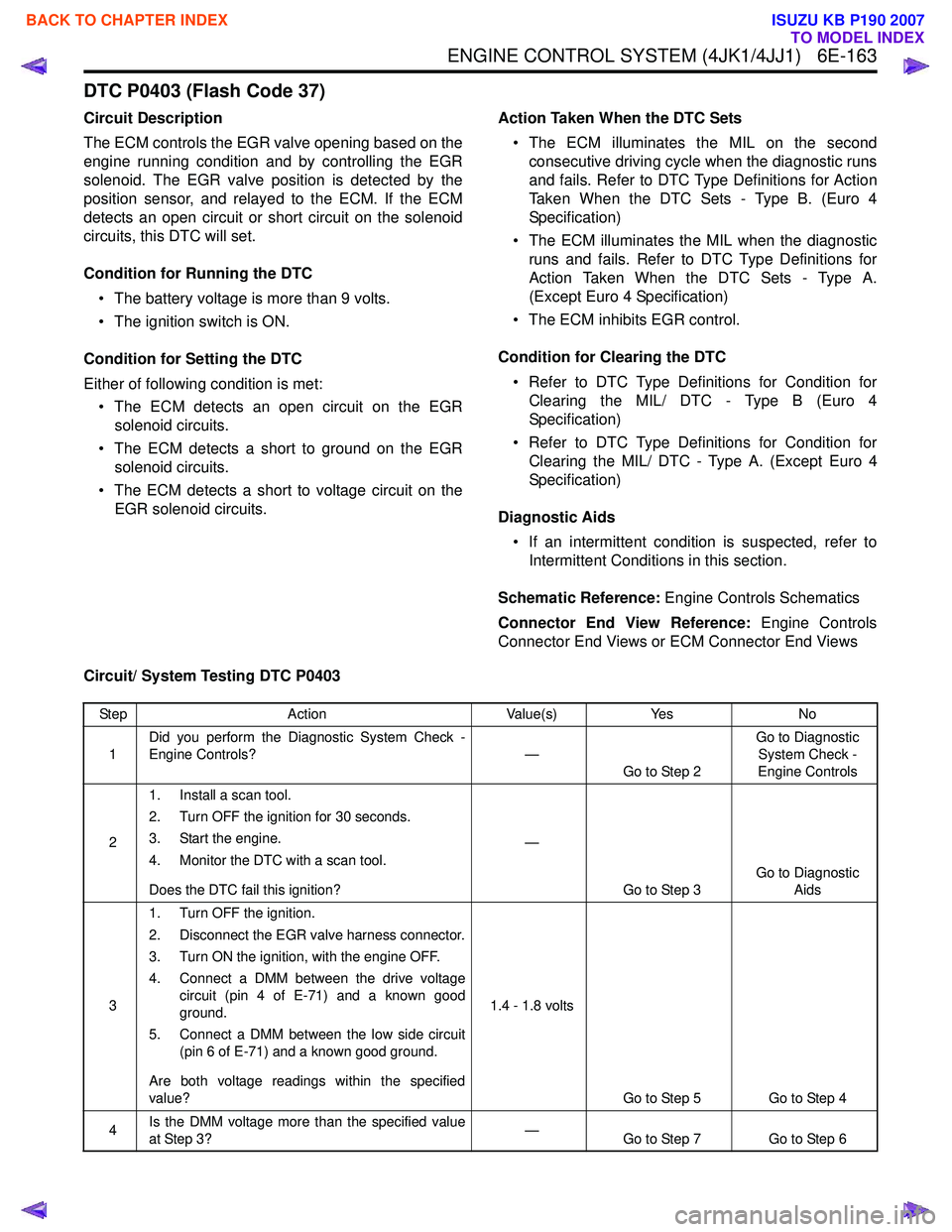
DTC P0403 (Flash Code 37)
Circuit Description
The ECM controls the EGR valve opening based on the
engine running condition and by controlling the EGR
solenoid. The EGR valve position is detected by the
position sensor, and relayed to the ECM. If the ECM
detects an open circuit or short circuit on the solenoid
circuits, this DTC will set.
Condition for Running the DTC • The battery voltage is more than 9 volts.
• The ignition switch is ON.
Condition for Setting the DTC
Either of following condition is met: • The ECM detects an open circuit on the EGR solenoid circuits.
• The ECM detects a short to ground on the EGR solenoid circuits.
• The ECM detects a short to voltage circuit on the EGR solenoid circuits. Action Taken When the DTC Sets
• The ECM illuminates the MIL on the second consecutive driving cycle when the diagnostic runs
and fails. Refer to DTC Type Definitions for Action
Taken When the DTC Sets - Type B. (Euro 4
Specification)
• The ECM illuminates the MIL when the diagnostic runs and fails. Refer to DTC Type Definitions for
Action Taken When the DTC Sets - Type A.
(Except Euro 4 Specification)
• The ECM inhibits EGR control.
Condition for Clearing the DTC • Refer to DTC Type Definitions for Condition for Clearing the MIL/ DTC - Type B (Euro 4
Specification)
• Refer to DTC Type Definitions for Condition for Clearing the MIL/ DTC - Type A. (Except Euro 4
Specification)
Diagnostic Aids • If an intermittent condition is suspected, refer to Intermittent Conditions in this section.
Schematic Reference: Engine Controls Schematics
Connector End View Reference: Engine Controls
Connector End Views or ECM Connector End Views
Circuit/ System Testing DTC P0403
Step Action Value(s)Yes No
1 Did you perform the Diagnostic System Check -
Engine Controls? —
Go to Step 2 Go to Diagnostic
System Check -
Engine Controls
2 1. Install a scan tool.
2. Turn OFF the ignition for 30 seconds.
3. Start the engine.
4. Monitor the DTC with a scan tool.
Does the DTC fail this ignition? —
Go to Step 3 Go to Diagnostic
Aids
3 1. Turn OFF the ignition.
2. Disconnect the EGR valve harness connector.
3. Turn ON the ignition, with the engine OFF.
4. Connect a DMM between the drive voltage circuit (pin 4 of E-71) and a known good
ground.
5. Connect a DMM between the low side circuit (pin 6 of E-71) and a known good ground.
Are both voltage readings within the specified
value? 1.4 - 1.8 volts
Go to Step 5 Go to Step 4
4 Is the DMM voltage more than the specified value
at Step 3? —
Go to Step 7 Go to Step 6
BACK TO CHAPTER INDEX
TO MODEL INDEX
ISUZU KB P190 2007
Page 1781 of 6020
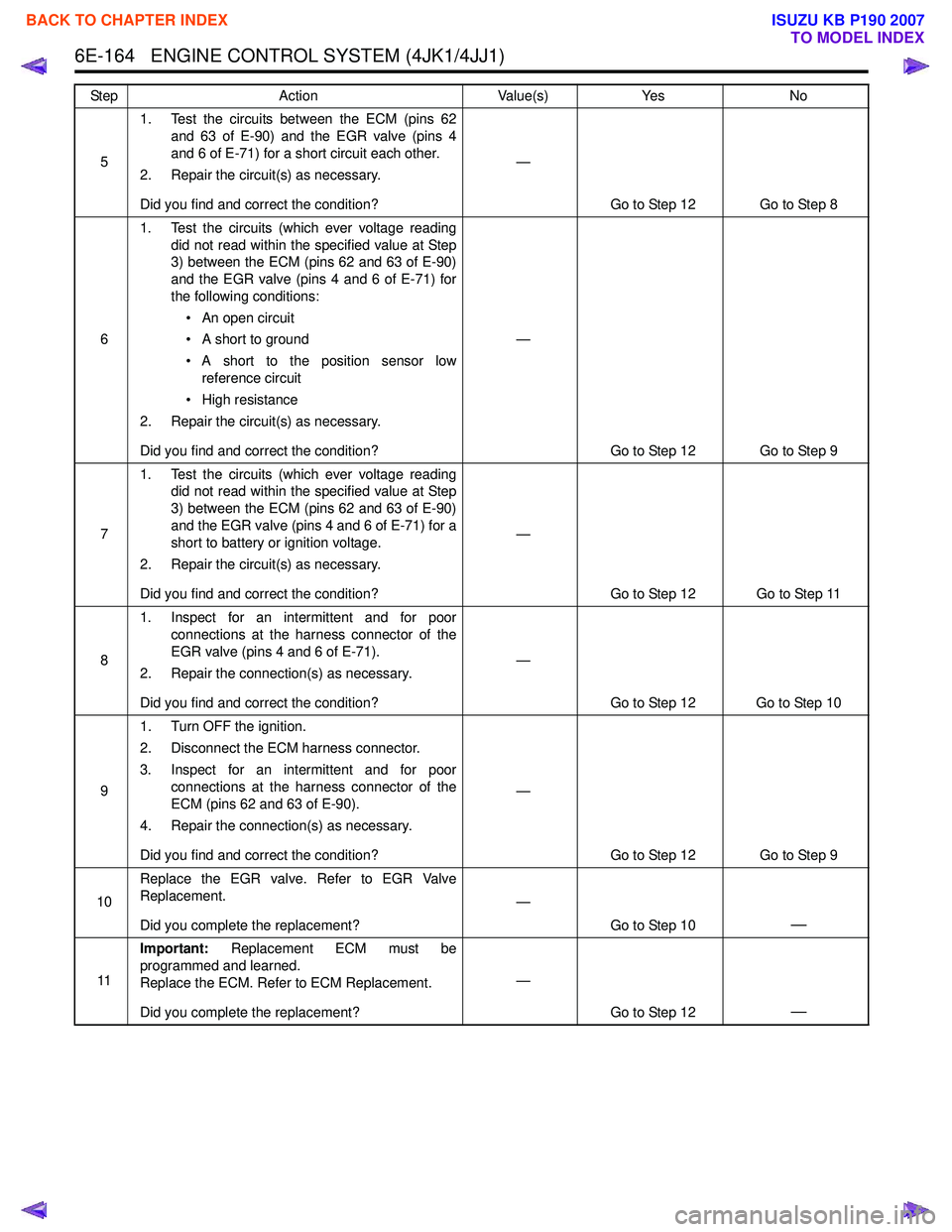
6E-164 ENGINE CONTROL SYSTEM (4JK1/4JJ1)
51. Test the circuits between the ECM (pins 62
and 63 of E-90) and the EGR valve (pins 4
and 6 of E-71) for a short circuit each other.
2. Repair the circuit(s) as necessary.
Did you find and correct the condition? —
Go to Step 12 Go to Step 8
6 1. Test the circuits (which ever voltage reading
did not read within the specified value at Step
3) between the ECM (pins 62 and 63 of E-90)
and the EGR valve (pins 4 and 6 of E-71) for
the following conditions:
• An open circuit
• A short to ground
• A short to the position sensor low reference circuit
• High resistance
2. Repair the circuit(s) as necessary.
Did you find and correct the condition? —
Go to Step 12 Go to Step 9
7 1. Test the circuits (which ever voltage reading
did not read within the specified value at Step
3) between the ECM (pins 62 and 63 of E-90)
and the EGR valve (pins 4 and 6 of E-71) for a
short to battery or ignition voltage.
2. Repair the circuit(s) as necessary.
Did you find and correct the condition? —
Go to Step 12 Go to Step 11
8 1. Inspect for an intermittent and for poor
connections at the harness connector of the
EGR valve (pins 4 and 6 of E-71).
2. Repair the connection(s) as necessary.
Did you find and correct the condition? —
Go to Step 12 Go to Step 10
9 1. Turn OFF the ignition.
2. Disconnect the ECM harness connector.
3. Inspect for an intermittent and for poor connections at the harness connector of the
ECM (pins 62 and 63 of E-90).
4. Repair the connection(s) as necessary.
Did you find and correct the condition? —
Go to Step 12 Go to Step 9
10 Replace the EGR valve. Refer to EGR Valve
Replacement.
Did you complete the replacement? —
Go to Step 10
—
11Important:
Replacement ECM must be
programmed and learned.
Replace the ECM. Refer to ECM Replacement.
Did you complete the replacement? —
Go to Step 12
—
Step Action Value(s)Yes No
BACK TO CHAPTER INDEX
TO MODEL INDEX
ISUZU KB P190 2007
Page 1782 of 6020
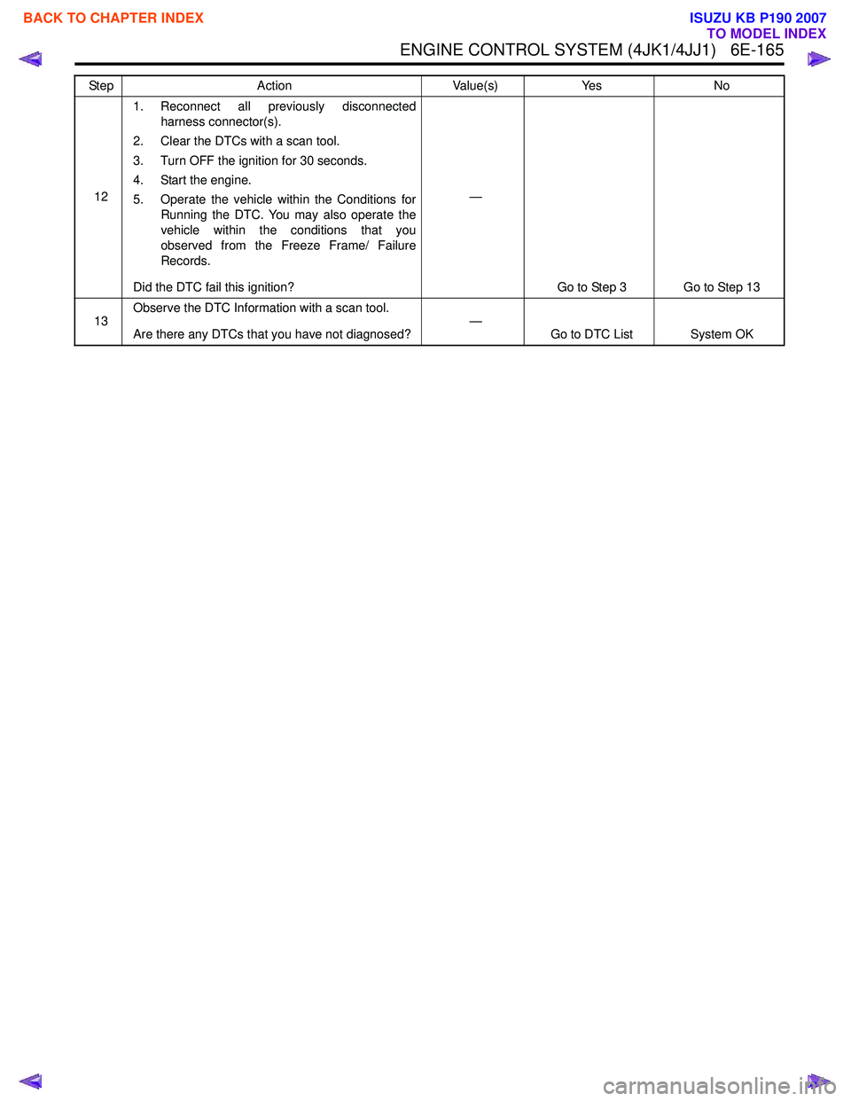
ENGINE CONTROL SYSTEM (4JK1/4JJ1) 6E-165
121. Reconnect all previously disconnected
harness connector(s).
2. Clear the DTCs with a scan tool.
3. Turn OFF the ignition for 30 seconds.
4. Start the engine.
5. Operate the vehicle within the Conditions for Running the DTC. You may also operate the
vehicle within the conditions that you
observed from the Freeze Frame/ Failure
Records.
Did the DTC fail this ignition? —
Go to Step 3 Go to Step 13
13 Observe the DTC Information with a scan tool.
Are there any DTCs that you have not diagnosed? —
Go to DTC List System OK
Step Action Value(s) Yes No
BACK TO CHAPTER INDEX
TO MODEL INDEX
ISUZU KB P190 2007
Page 1784 of 6020
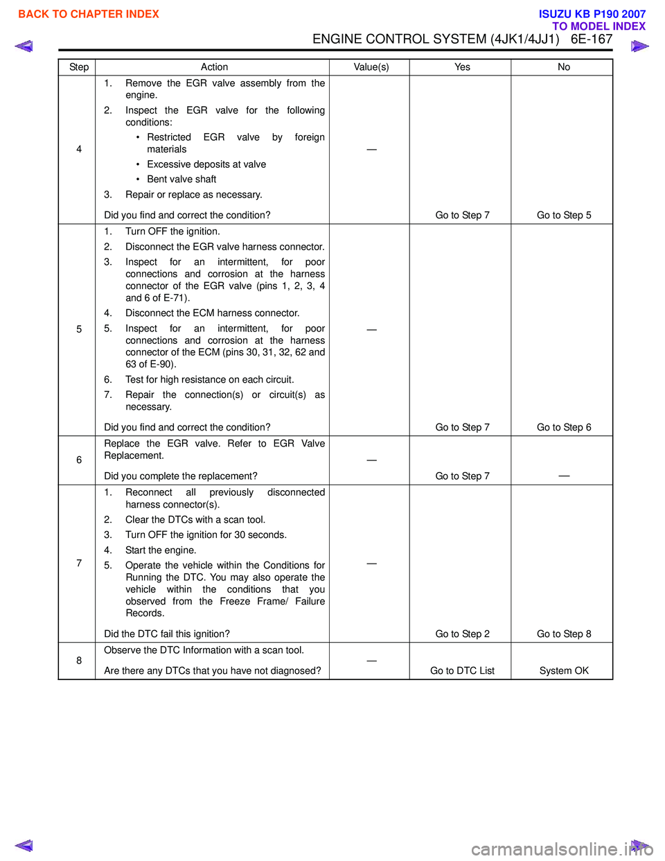
ENGINE CONTROL SYSTEM (4JK1/4JJ1) 6E-167
41. Remove the EGR valve assembly from the
engine.
2. Inspect the EGR valve for the following conditions:
• Restricted EGR valve by foreign materials
• Excessive deposits at valve
• Bent valve shaft
3. Repair or replace as necessary.
Did you find and correct the condition? —
Go to Step 7 Go to Step 5
5 1. Turn OFF the ignition.
2. Disconnect the EGR valve harness connector.
3. Inspect for an intermittent, for poor connections and corrosion at the harness
connector of the EGR valve (pins 1, 2, 3, 4
and 6 of E-71).
4. Disconnect the ECM harness connector.
5. Inspect for an intermittent, for poor connections and corrosion at the harness
connector of the ECM (pins 30, 31, 32, 62 and
63 of E-90).
6. Test for high resistance on each circuit.
7. Repair the connection(s) or circuit(s) as necessary.
Did you find and correct the condition? —
Go to Step 7 Go to Step 6
6 Replace the EGR valve. Refer to EGR Valve
Replacement.
Did you complete the replacement? —
Go to Step 7
—
71. Reconnect all previously disconnected
harness connector(s).
2. Clear the DTCs with a scan tool.
3. Turn OFF the ignition for 30 seconds.
4. Start the engine.
5. Operate the vehicle within the Conditions for Running the DTC. You may also operate the
vehicle within the conditions that you
observed from the Freeze Frame/ Failure
Records.
Did the DTC fail this ignition? —
Go to Step 2 Go to Step 8
8 Observe the DTC Information with a scan tool.
Are there any DTCs that you have not diagnosed? —
Go to DTC List System OK
Step
Action Value(s)Yes No
BACK TO CHAPTER INDEX
TO MODEL INDEX
ISUZU KB P190 2007