Page 4754 of 6020

Manual Transmission (MUX) 7B1-35
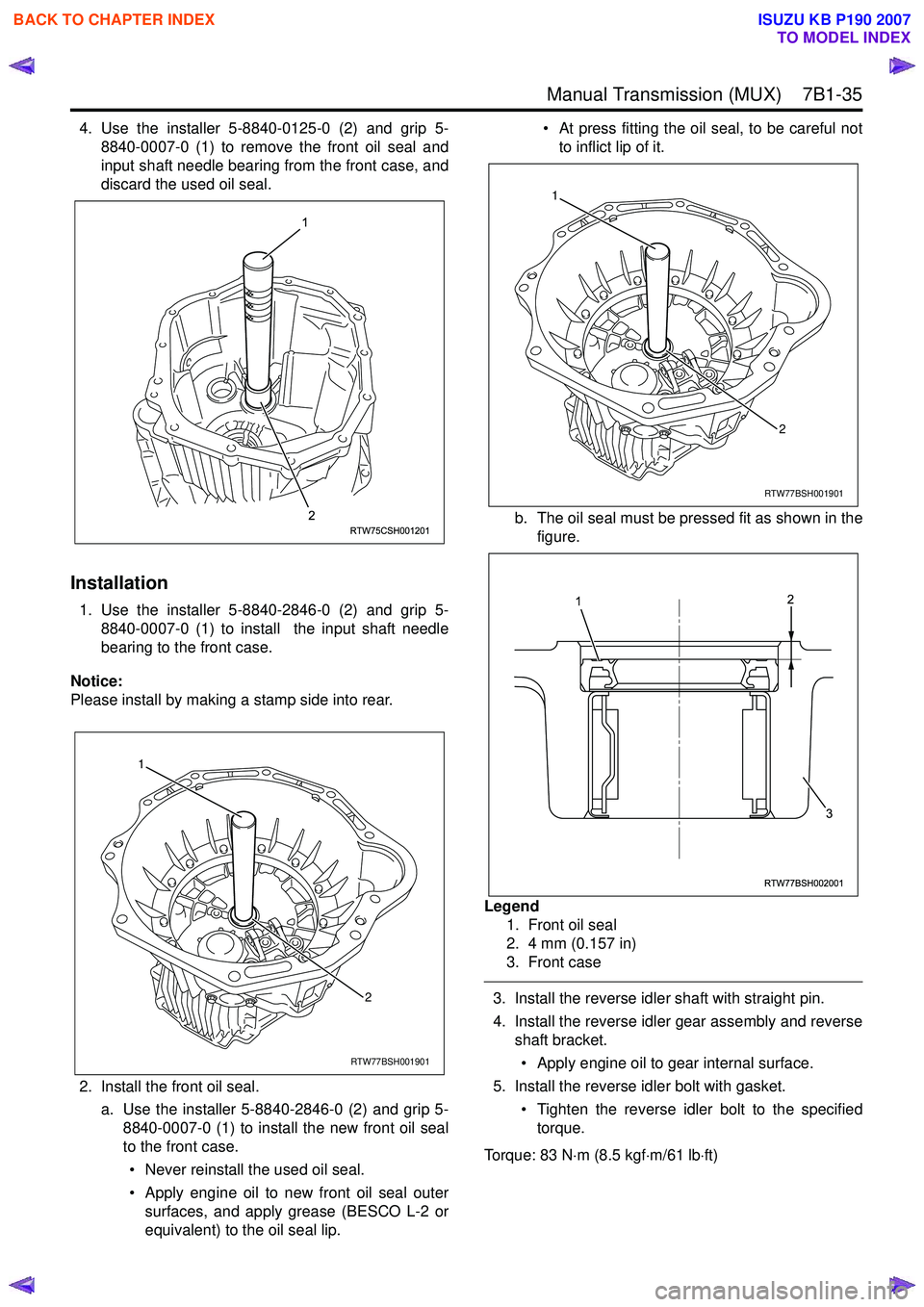
4. Use the installer 5-8840-0125-0 (2) and grip 5-8840-0007-0 (1) to remove the front oil seal and
input shaft needle bearing from the front case, and
discard the used oil seal.
Installation
1. Use the installer 5-8840-2846-0 (2) and grip 5- 8840-0007-0 (1) to install the input shaft needle
bearing to the front case.
Notice:
Please install by making a stamp side into rear.
2. Install the front oil seal. a. Use the installer 5-8840-2846-0 (2) and grip 5- 8840-0007-0 (1) to install the new front oil seal
to the front case.
• Never reinstall the used oil seal.
• Apply engine oil to new front oil seal outer surfaces, and apply grease (BESCO L-2 or
equivalent) to the oil seal lip. • At press fitting the oil seal, to be careful not
to inflict lip of it.
b. The oil seal must be pressed fit as shown in the figure.
Legend 1. Front oil seal
2. 4 mm (0.157 in)
3. Front case
3. Install the reverse idler shaft with straight pin.
4. Install the reverse idler gear assembly and reverse shaft bracket.
• Apply engine oil to gear internal surface.
5. Install the reverse idler bolt with gasket.
• Tighten the reverse idler bolt to the specifiedtorque.
Torque: 83 N ⋅m (8.5 kgf ⋅m/61 lb ⋅ft)
RTW75CSH001201
1
2
RTW77BSH001901
1 2
RTW77BSH001901
12
RTW77BSH002001
2
1
3
BACK TO CHAPTER INDEX
TO MODEL INDEX
ISUZU KB P190 2007
Page 4758 of 6020
Manual Transmission (MUX) 7B1-39
End Cover Assembly
Component
Legend1. Rear oil seal (4x2 model)
2. End cover (4x2 model) 3. Rear oil seal (4x4 model)
4. End cover (4x4 modeel)
Removal
1. Remove the rear oil seal from the end cover, and discard the used oil seal.
Installation
1. Use the installer 5-8840-2786-0 to install the newrear oil seal to the end cover. (4x2 model)
Use the installer 5-8840-2282-0 (1) to install the
new rear oil seal to the end cover. (4x4 model)
• Never reinstall the used oil seal.
• Apply engine oil to new rear oil seal outer surfaces, and apply grease (BESCO L-2 or
equivalent) to the oil seal lip.
• At press fitting the oil seal, to be careful not to inflict lip of it.
RTW77BSF000501
1
2
3
4
RTW75CSH001301
1
BACK TO CHAPTER INDEX
TO MODEL INDEX
ISUZU KB P190 2007
Page 4766 of 6020

Manual Transmission (MUX) 7B1-47
Installation
1. Install the needle bearing, 2nd counter gearassembly, 2nd inside ring, 2nd outside ring, and
2nd block ring.
• Apply engine oil to the needle bearing and gear internal surface.
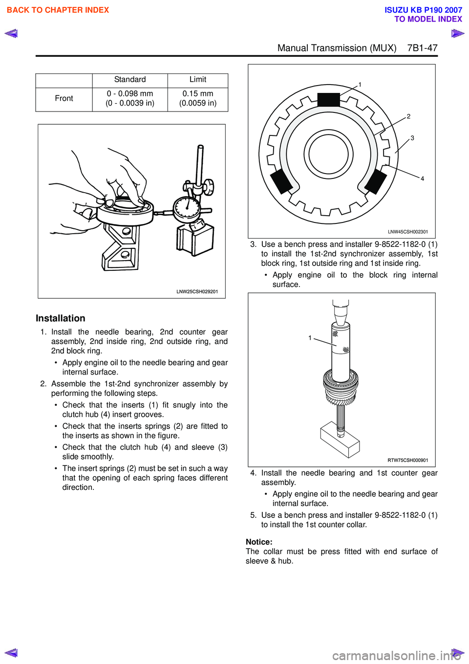
2. Assemble the 1st-2nd synchronizer assembly by performing the following steps.
• Check that the inserts (1) fit snugly into the clutch hub (4) insert grooves.
• Check that the inserts springs (2) are fitted to the inserts as shown in the figure.
• Check that the clutch hub (4) and sleeve (3) slide smoothly.
• The insert springs (2) must be set in such a way that the opening of each spring faces different
direction. 3. Use a bench press and installer 9-8522-1182-0 (1)
to install the 1st-2nd synchronizer assembly, 1st
block ring, 1st outside ring and 1st inside ring.
• Apply engine oil to the block ring internal surface.
4. Install the needle bearing and 1st counter gear assembly.
• Apply engine oil to the needle bearing and gear internal surface.
5. Use a bench press and installer 9-8522-1182-0 (1) to install the 1st counter collar.
Notice:
The collar must be press fitted with end surface of
sleeve & hub.
Standard
Limit
Front 0 - 0.098 mm
(0 - 0.0039 in) 0.15 mm
(0.0059 in)
LNW25CSH029201
LNW45CSH002301
1
23
4
RTW75CSH000901
1
BACK TO CHAPTER INDEX
TO MODEL INDEX
ISUZU KB P190 2007
Page 4767 of 6020

7B1-48 Manual Transmission (MUX)
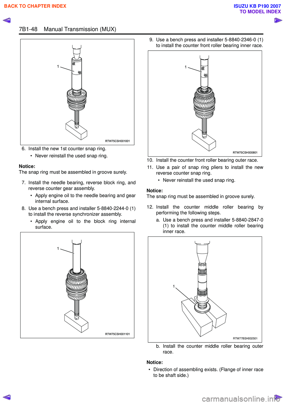
6. Install the new 1st counter snap ring.• Never reinstall the used snap ring.
Notice:
The snap ring must be assembled in groove surely.
7. Install the needle bearing, reverse block ring, and reverse counter gear assembly.
• Apply engine oil to the needle bearing and gear internal surface.
8. Use a bench press and installer 5-8840-2244-0 (1) to install the reverse synchronizer assembly.
• Apply engine oil to the block ring internal surface. 9. Use a bench press and installer 5-8840-2346-0 (1)
to install the counter front roller bearing inner race.
10. Install the counter front roller bearing outer race. 11. Use a pair of snap ring pliers to install the new reverse counter snap ring.
• Never reinstall the used snap ring.
Notice:
The snap ring must be assembled in groove surely.
12. Install the counter middle roller bearing by performing the following steps.
a. Use a bench press and installer 5-8840-2847-0 (1) to install the counter middle roller bearing
inner race.
b. Install the counter middle roller bearing outer race.
Notice: • Direction of assembling exists. (Flange of inner race to be shaft side.)
RTW75CSH001001
1
RTW75CSH001101
1
RTW75CSH000801
1
RTW77BSH002501
1
BACK TO CHAPTER INDEX
TO MODEL INDEX
ISUZU KB P190 2007
Page 4780 of 6020
7C-2 CLUTCH
MAIN DATA AND SPECIFICATIONS
ENGINE 4JJ1
(High Output) 4JA1-T 4JK1-TC 4JJ1 (Standard Output)
4JH1-TC C24SE
TRANSMISSION MUX MSG MUA MUA
Clutch type
Dry single plate with diaphragm
Size mm (in) 275 (10.83) 225 (8.86) 250 (9.84) 240 (9.45)
Clamping force kg(lb) 700 (1544) 517 (1140) 640 (1411) 560 (1235)
(N) (6860) (5070) (6300) (5500)
Pressure plate
Outside diameter mm(in) 275 (10.83) 225 (8.86) 250 (9.84) 240 (9.45)
Inside diameter mm(in) 180 (7.087) 150 (5.906) 160 (6.299) 160 (6.299)
Driven plate
Thickness mm(in)
at free 8.8 (0.346) 8.4 (0.331) 8.3 (0.327) 8.7 (0.342)
at compressed 8.3 (0.327) 7.8 (0.307) 7.8 (0.307) 8.0 (0.315)
Clutch Cont. type Hydraulic
Pedal free play mm(in) 5.0-15.0 (0.2-0.6)
Master cylinder
Bore×Stroke mm(in) 15.87 × 35 (0.625 × 1.38)
Slave cylinder
Bore × Stroke mm(in) 22.22 × 18.9
(0.875 × 0.744) 19.05
× 23
(0.749 × 0.906) 20.64
× 23
(0.813 × 0.906) 19.05
× 23
(0.749 × 0.906)
BACK TO CHAPTER INDEX
TO MODEL INDEX
ISUZU KB P190 2007
Page 4837 of 6020
TRANSFER CASE 7D-7
Installation
1. Thoroughly clean around the oil seal bore in the case
and ensure there are no burrs.
2.
Apply the engine oil to the new oil seal outer surfaces
and apply the recommended grease (BESCO L2) o
r
equivalent to the oil seal lip.
3. Tap the oil seal in to place, use an oil seal installe
r
(5-8840-2785-0) and a soft hammer.
RTW 77DSH000301
4. Install the output flange to the front output shaft.
5. Apply the engine oil to the new O-ring and install it to the front output shaft.
6. Secure the output flange with a flange holde
r
(5-8840-0133-0).
7. Install the new end nut and tighten them to specified torque.
Front coupling driver fixing nut torque: 137 N ⋅
⋅⋅
⋅
m (14.0 kgf ⋅
⋅⋅
⋅
m/101 lb ⋅
⋅⋅
⋅
ft)
8. Use a punch (5-8840-2293-0) to caulk the end nut.
226R300012
RUW 34DSH000301
Legend
(1) MAX 26mm (1.02in)
(2) MIN 4mm (0.16in)
BACK TO CHAPTER INDEX
TO MODEL INDEX
ISUZU KB P190 2007
Page 4839 of 6020
TRANSFER CASE 7D-9
Transfer Case Rear Oil Seal
Transfer Rear Oil Seal and Associated Parts
220R300018
Legend
(1) Rear Propeller Shaft
(2) Rear Oil Seal
Removal
1. Disconnect the battery ground cable.
2. Raise and support the vehicle with suitable stands.
3. Remove the rear propeller shaft.
4. Remove the oil seal from the transfer case.
Installation
1. Thoroughly clean around the oil seal bore in the
transfer case and ensure there are no burrs.
2.
Apply the engine oil to the new oil seal outer surfaces
and apply the recommended grease (BESCO L2) o
r
equivalent to the oil seal lip.
BACK TO CHAPTER INDEX
TO MODEL INDEX
ISUZU KB P190 2007
Page 4848 of 6020
7D-18 TRANSFER CASE
Transfer Disassembly
RTW 67DLF000101
Legend
(1) Transfer Case Speedometer Bushing, Plate and Driven Gear
(2) Companion Flange, O-ring and Nut
(8)
(M/T: MUA, MUX, A/T: JR405E, AW 30-40LE)
(3) Stoneguard (9) Speed sensor (M/T: AR-5, A/T: 4L60-E)
(4) Detent Plug, Spring and Detent Ball (10) Transfer Actuator (Diesel Engine)
(5) 2-4 Switch ASM (11) Transfer Actuator (Gasoline Engine)
(6) Switch Bracket (12) Breather Hose
(7) Neutral Switch ASM (13) Heat Protector (Gasoline Engine)
Removal
1. Remove the stoneguard.
2. Remove the drain plug from the transfer case to drain
the oil.
3. Remove the parts listed below.
• Speedometer bushing, plate, and speedomete
r
driven gear (M/T: MUA, MUX, A/T: JR405E,
AW 30-40LE)
• Speed sensor (M/T: AR-5, A/T: 4L60-E)
BACK TO CHAPTER INDEX
TO MODEL INDEX
ISUZU KB P190 2007